Robot
This page describes the Robot step of a solution, where you choose the robot model the solution works with. It also covers robots mounted on a wall or the ceiling, and the base frame offset that some robot brands need. It applies to Bin Picking Studio (BPS) solutions only, the CAD Picking and AI Picking solution types.
Robot list
The Robot page shows a list of robot models. Each robot shows its name and manufacturer, its reach and payload, a status, and a Select button.
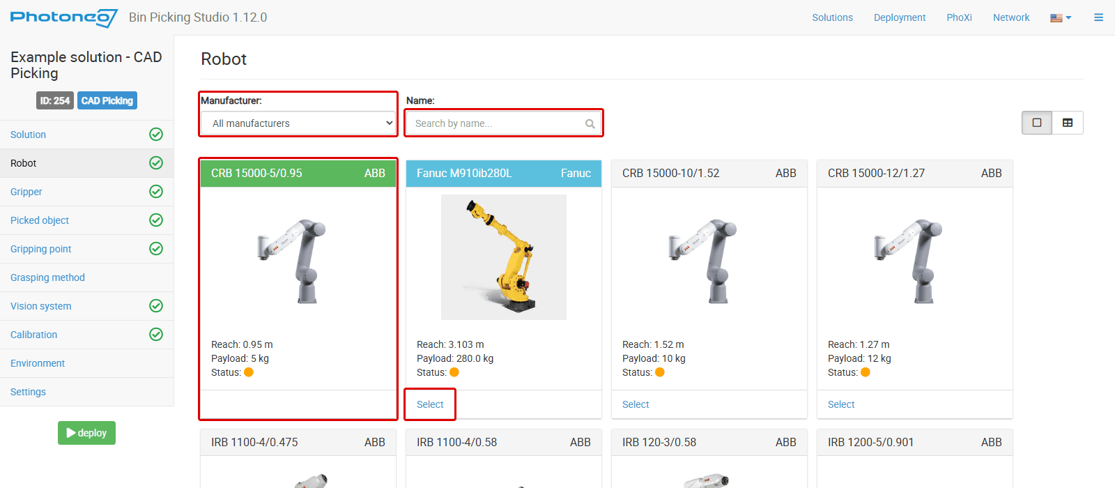
The Robot page. Red frames: the Manufacturer filter, the Name search, the selected robot (green) and the Select button of another robot.
Use the filters above the list to find a model:
Manufacturer - shows only the robots of one manufacturer. The default is All manufacturers.
Name - searches the list by robot name.
The Cards view and Table view buttons switch between two layouts of the list.
The help text of the page says: “Custom robots are designated by a blue frame.”
Supported manufacturers
The list in BPS 1.12 contains robot models by these manufacturers:
ABB
Denso
Doosan
Epson
Estun
Fanuc
HD Hyundai Robotics
Kawasaki
KUKA
KUKA LBR iiwa
Mitsubishi
Nachi
RobCo
Stäubli
Techman Robot
Universal Robots
Yaskawa
The exact robot models are listed on the Robot page of the Studio. The list can change between releases.
Selecting a robot
To choose the robot of the solution:
Open the Robot step of the solution.
Find the robot model with the Manufacturer and Name filters.
Click Select on the robot.
Read the confirmation message and click Proceed.
When you select a different robot model, the Studio makes these changes automatically:
Joint limits will be reset.
The calibration point dataset will be removed in all vision systems.
Automatic calibration feature will be disabled in all vision systems.
Because the joint limits are reset and the calibration point datasets are removed, check the joint limits and calibrate the vision systems again after you change the robot. See Joint limits and Calibration.
The help text of the page also notes that correct network information is essential to keep the connection with the robot. The robot connection is set up on the Network page, see Robot interface.
Robot mount orientation
A new Bin Picking Studio (BPS) solution assumes a floor-mounted robot. Robots mounted on a wall or on the ceiling are supported too, but a few settings must then be changed, because they are vectors in the robot base coordinate system (robot space). This section shows what to change for the three most common mount positions: floor, wall and ceiling.
Robot space
Robot space has its origin in the robot base. Its X, Y and Z axes are the red, green and blue arrows in the 3D viewer. When the robot is not on the floor, the Z-axis of robot space no longer points up:
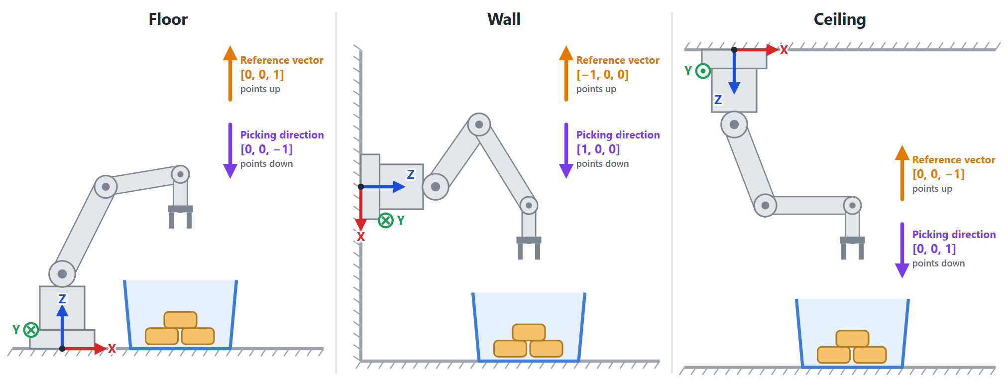
The same cell with a floor, wall and ceiling mounted robot. The “up” reference vector and the picking direction stay the same in the real world, but their values in robot space change. In the wall example, the X-axis of the robot points down.
Note
Robots of all supported brands use the X-axis as the forward direction, except Kawasaki, which uses the Y-axis. On a wall, the values also depend on how the robot is turned. Look at the axes of the robot base in the 3D viewer and write the real-world “up” direction in those axes.
Model the cell in the Environment step
Build the scene in the Environment step so it matches the real cell. For a wall or ceiling robot, rotate the scene (floor, bins, walls) until it matches reality, then check in the 3D viewer where the axes of robot space point.
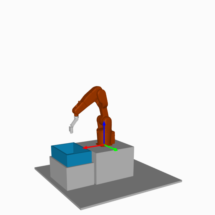
|
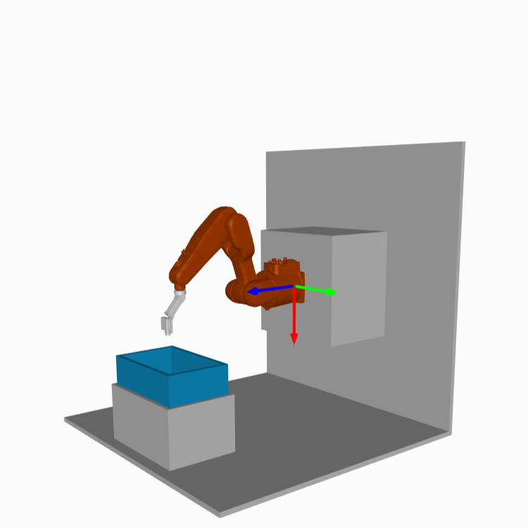
|
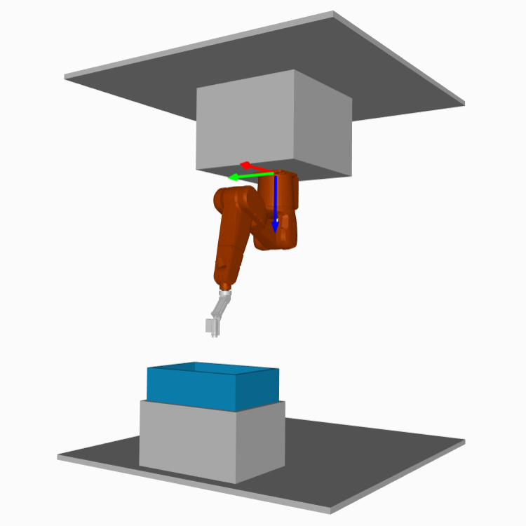
|
Floor |
Wall |
Ceiling |
Screenshots from an older Studio version.
Settings to change
Setting |
Floor |
Wall |
Ceiling |
|---|---|---|---|
Gripper angle → Reference vector X / Y / Z Points up in the real world. |
0, 0, 1 (default) |
−1, 0, 0 |
0, 0, −1 |
Picking priority → Picking direction vector X / Y / Z Order in which objects are picked. It normally points down, so the objects on top are picked first. |
0, 0, −1 (default) |
1, 0, 0 |
0, 0, 1 |
Example: a path stage 100 mm above the previous waypoint, origin Robot Relative offset X / Y / Z [mm] |
0, 0, 100 |
−100, 0, 0 |
0, 0, −100 |
Both settings are global settings and can be overridden per vision system.
Grasping method
Path stages that are defined in robot space need care when the robot is not on the floor:
Relative, origin Robot, Start or End: the relative offset is in robot space. “Up” is not +Z, see the last row of the table above. The Studio help text “the Z-axis points up” is only true for a floor-mounted robot.
Relative, origin Fixed plane: supported. Choose the plane (XY, XZ or YZ) and the Relative offset value in robot space, and check the direction of the move.
Fixed: the Absolute position X / Y / Z is in robot space.
Relative, origin Found gripping point: not affected, because the offset follows the gripping point.
See Grasping methods for the path stage types.
Base frame offsets
Robots report the position of their tool point relative to the origin of their base frame. For Fanuc, Kawasaki, Stäubli and Yaskawa robots, this origin is not where the robot model in Bin Picking Studio (BPS) has it:
the robot controller has the origin at the height of the second joint (J2), on the axis of the first joint,
the robot model in BPS has it at the very bottom of the robot base.
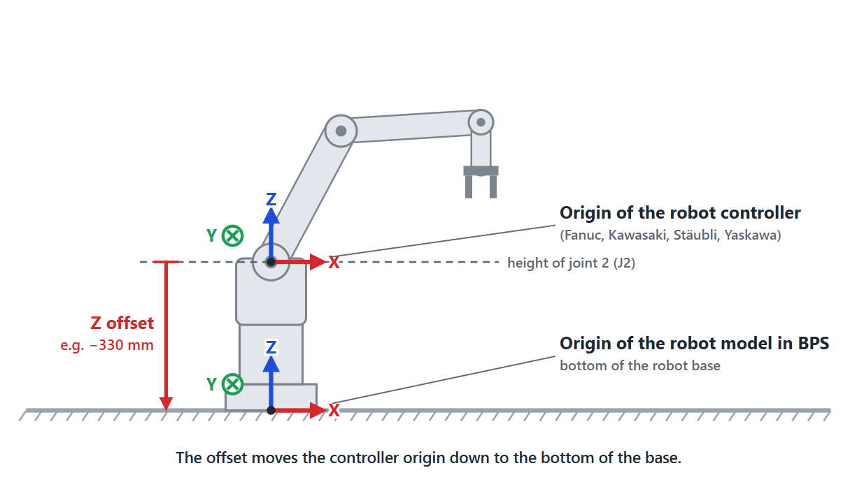
The Z offset moves the origin of the robot controller down to the bottom of the robot base, where the robot model in BPS has it.
Without the offset, the poses that the robot reports and the poses that BPS sends do not match, and calibration fails. Set the offset once in the robot controller, before calibration.
Warning
Changing the base or user frame of the robot can move positions that were already taught in that frame.
Where to set the offset
Brand |
Robot controller |
Steps |
|---|---|---|
Fanuc |
Menu → Setup → Frames → User Frame 1, value Z |
|
Kawasaki |
Menu → Aux Functions → Advanced Settings → Base Coordinates, value Z |
|
Stäubli |
Data tab → photoneo_common → frame → fBaseLink, value Z |
|
Yaskawa |
Robot → User Coordinate → USER COORDINATE 1, value Z |
The tables below list the Z offset of each robot of these brands in the BPS 1.12 robot list. If your robot is not listed (for example a custom robot model from Photoneo support), take the height of J2 above the bottom of the base from the working envelope drawing in the robot documentation, and use it as a negative value.
Fanuc
Set the offset in User Frame 1.
Model |
Z offset [mm] |
|---|---|
ARC Mate 100iC/12 |
-450 |
ARC Mate 100iD |
-450 |
ARC Mate 100iD/10L |
-450 |
ARC Mate 120iC |
-525 |
ARC Mate 120iD |
-425 |
CR-35iA |
-1180 |
CR-35iB |
-668 |
CR-7iA |
-457 |
CR-7iA/L |
-457 |
CRX-10iA |
-245 |
CRX-10iA/L |
-245 |
CRX-20iA/L |
-245 |
CRX-25iA |
-370 |
CRX-30iA |
-370 |
CRX-5ia |
-185 |
LR Mate 200iD |
-330 |
LR Mate 200iD/4S |
-330 |
LR Mate 200iD/7L |
-330 |
LR-10iA/10 |
-400 |
M-1000iA |
-1050 |
M-10iA/10M |
-450 |
M-10iA/10MS |
-450 |
M-10iA/10S |
-450 |
M-10iA/12 |
-450 |
M-10iA/12S |
-450 |
M-10iA/7L |
-450 |
M-10iA/8L |
-450 |
M-10iD/12 |
-450 |
M-10iD/8L |
-450 |
M-20iA |
-525 |
M-20iA/20M |
-525 |
M-20iA/35M |
-525 |
M-20iB/25 |
-650 |
M-20iD/12L |
-425 |
M-20iD/25 |
-425 |
M-20iD/35 |
-425 |
M-430iA/2P |
-410 |
M-430iA/2PH |
-440 |
M-710iC/12L |
-565 |
M-710iC/20L |
-565 |
M-710iC/45M |
-565 |
M-710iC/50 |
-565 |
M-710iC/50S |
-565 |
M-900iA/260L |
-950 |
M-900iA/600F |
-1000 |
M-900iB/400L |
-940 |
M-900iB/700 |
-940 |
P-40iA |
-618 |
R-1000iA/100F |
-450 |
R-1000iA/100F IF |
-450 |
R-1000iA/130F IF |
-450 |
R-2000iA/165F |
-670 |
R-2000iA/165F IF |
-670 |
R-2000iB/165F |
-670 |
R-2000iB/165F IF |
-670 |
R-2000iB/210F |
-670 |
R-2000iB/250F IF |
-670 |
R-2000iC/125L |
-670 |
R-2000iC/165F |
-670 |
R-2000iC/165R |
-670 |
R-2000iC/210F |
-670 |
R-2000iC/210F IF |
-670 |
R-2000iC/210L |
-670 |
R-2000iC/210L IF |
-670 |
R-2000iC/270F |
-670 |
R-2000iD/100FH |
-670 |
R-2000iD/100FH IF |
-670 |
R-2000iD/210FH IBF |
-670 |
R-2000iD/210FH IF |
-670 |
Kawasaki
Set the offset in the Base Coordinates. The Kawasaki Astorino in the robot list has no value here; take it from the robot documentation.
Model |
Z offset [mm] |
|---|---|
BA-006L |
-430 |
BX-100L |
-530 |
BX-200L |
-530 |
BX-200L-C011 |
-530 |
RS-003N |
-250 |
RS-005L |
-295 |
RS-005N |
-295 |
RS-006L |
-430 |
RS-007L |
-360 |
RS-007N |
-360 |
RS-010L |
-465 |
RS-010N |
-430 |
RS-013N |
-505 |
RS-015X |
-680 |
RS-020N |
-465 |
RS-025N |
-580 |
RS-030N |
-680 |
RS-050N |
-680 |
RS-080N |
-680 |
ZS-100U |
-530 |
Stäubli
Set the offset in the fBaseLink frame of the robot module.
Model |
Z offset [mm] |
|---|---|
RX160 |
-550 |
RX160L |
-550 |
TX2-140 |
-550 |
TX2-160 |
-550 |
TX2-160L |
-550 |
TX2-40 |
-320 |
TX2-60 |
-375 |
TX2-60L |
-375 |
TX2-90 |
-478 |
TX2-90L |
-478 |
TX2-90XL |
-478 |
TX200 |
-642 |
TX200L |
-642 |
TX40 |
-320 |
TX60 |
-375 |
TX60L |
-375 |
TX90 |
-478 |
TX90L |
-478 |
TX90XL |
-478 |
Yaskawa
Set the offset in USER COORDINATE 1.
Model |
Z offset [mm] |
|---|---|
GP12 |
-450 |
GP180 |
-650 |
GP180-120 |
-650 |
GP20 |
-505 |
GP215 |
-650 |
GP225 |
-650 |
GP25 |
-505 |
GP25-12 |
-505 |
GP35L |
-540 |
GP4 |
-330 |
GP50 |
-540 |
GP7 |
-330 |
GP70L |
-540 |
GP8 |
-330 |
GP88 |
-540 |
HC10 |
-275 |
HC10DT-A |
-275 |
HC10DT-B |
-275 |
HC20DTP |
-380 |
HC30PL |
-380 |
MA2010 |
-505 |
MH12 |
-450 |
MH24 |
-505 |
MH24-10 |
-505 |
MH3BM |
-350 |
MH3F |
-290 |
MH50-35 |
-540 |
MH50II-K00 |
-540 |
MH5LSII |
-330 |
MH5SII |
-330 |
MotoMINI |
-171 |
SP165 |
-650 |
SP180H |
-650 |
Further robot configuration
Besides the model, the mount orientation and the base frame offset above, the robot is configured in these places:
- Set on the Environment page. Joint limits define the space the path planning works in.
- Calibration of the vision systems against the robot.
- Setting up the robot controller and the robot module for each robot brand.