Network setup

This chapter documents network settings and troubleshooting of network-related issues between the vision controller and other connected hardware.

Contents

1 Network topology

The basic application consists of the vision controller, one 3D sensor, and, naturally, a robot with its controller. The core of the system is the vision controller to which the other hardware components are linked using ethernet cables.

1.1 Dedicated Ethernet ports

The vision controller is equipped with 6 ethernet ports - from left to right they are dedicated to:

Sensors
The first four ports are dedicated to connection of Photoneo 3D sensors, on the vision controller they carry the label Sensor. A sensor should be connected to the vision controller using a cable of Cat5e category or higher that supports Gigabit ethernet in order to achieve maximum transfer speed. The sensor can be connected either directly to the vision controller or using a Gigabit switch.
The usage of a switch is necessary when connecting more than four sensors to a single vision controller. In this case, on the vision controller, the ethernet cable from the switch would be connected to any of the sensor-dedicated ports.
Network
A physical network port labeled Network can be used to connect the vision controller to the Internet, factory network, or directly to another computer. Then it is possible to remotely control the Studio by one of the available Remote access methods.
Robotic controller
It is recommended to connect the robotic controller to the vision controller directly without using any additional communication device between them. On the vision controller, the ethernet cable is connected to the physical network port labeled Robot.
The vision controller communicates with the robotic controller over TCP/IP. No other communication protocols are currently supported.

1.2 Exemplary network topologies

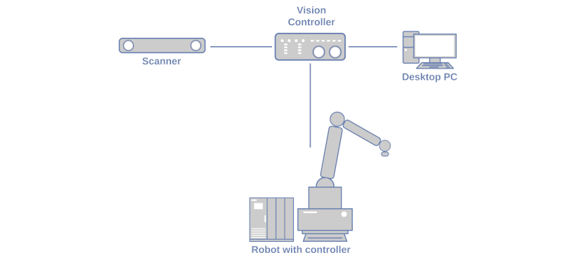
Example 1 - Minimal connection scheme
A single Photoneo 3D sensor (a PhoXi 3D Scanner in this case) is connected to a sensor port of the vision controller.
A Desktop PC for remote control is connected directly to the Network port of the vision controller.
The robot controller is connected directly to the Robot port of the vision controller.
image1
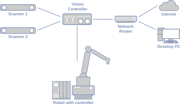
Example 2 - Scheme with multiple sensors and the vision controller connected to LAN with Internet access
Two Photoneo 3D sensors (PhoXi 3D Scanners in this case) are connected to two sensor ports of the vision controller..
The vision controller is connected to the local network (LAN) through a Network router. The vision controller has access to the Internet (if available on the LAN) and other devices on the LAN have access to the vision controller (remote control).
The robot controller is connected directly to the Robot port of the vision controller.
image2

1.3 Banned IP ranges

The following rules apply when configuring the network interfaces on the Network page:

  • Subnets of individual network interfaces cannot overlap

  • Moreover, the following subnets are Photoneo-reserved, and therefore, it is also not possible to configure any subnet overlapping with any of them:

    • 169.254.0.0/16

    • 172.18.0.0/28

    • 192.168.101.0/24

2 Network configuration

Network interfaces of the vision controller are configured on the Network page of the Studio. Through these interfaces, the vision controller communicates with all connected hardware components of the application. Correct network setup is a fundamental part of the Studio configuration to achieve a working, robust and stable run of your application.

2.1 Robot interface

The Robot interface of the Network page serves for the configuration of the interface through which the vision controller communicates with the robotic controller.
This section is divided into two subsections:
  • Vision controller used for network setup of the Ethernet port on the vision controller. A static IPv4 address must be used (manual IPv4 method).

  • Robot controller used for network setup of the robotic controller. The IP address of the robot must be input here as configured on the robotic controller.

Make sure both the robot interface IP address and the robot controller IP address are on the same subnet.
As described in the Robot communication overview, the communication between the vision controller and the robotic controller is realized using two channels - the Action Request Communication Channel and the Robot State Communication Channel (Bin Picking Studio only). Both the vision controller and the robotic controller create their own TCP servers. The vision controller creates one to which the robotic controller connects for sending requests. The robotic controller creates one to which the vision controller connects for reading the robot state data.
These TCP servers run on default ports and it is recommended not to change them - leave the Action Request Server port (ARS port) and Robot State Server port (RSS port) fields empty. Should it be necessary to use a custom port either for the Action Request Server or the Robot State Server, the chosen port value must be filled in the corresponding port field. Keep in mind that in that case, the same change needs to be done on the robot side (in the Robot Module).

2.2 Sensor interfaces

In this section of the Network page it is possible to configure the four interfaces through which the vision controller communicates with the connected Photoneo 3D sensor(s). Static IPv4 addresses must be used (manual IPv4 method).

The sensor is a network device, therefore, it needs a unique IP address so the vision controller on the same network can identify and communicate with it. The sensor is assigned an IPv4 as well as an IPv6 address. The IPv6 link-local address is fixed, the IPv4 address can be configured by the user through the PhoXi Control application.
IPv6 connection is preferred over IPv4. However, should the IPv6 connection fail, the IPv4 address is used. Therefore, it is recommended to have a valid IPv4 network configuration.

The Sensor #1 interface can be configured to run a DHCP server which can then assign an IPv4 address to a connected sensor with DHCP client. Sensor interface #2, #3 and #4 don’t provide this function.
DHCP server
Turns ON the DHCP server on the Sensor #1 interface on fixed static IPv4 address 192.168.101.1. PhoXi Control is used to set the connected 3D sensor(s) to the DHCP client by choosing the IP assignment type DHCP. The sensor(s) will then be assigned an IP address from the range 192.168.101.2 - 192.168.101.255.
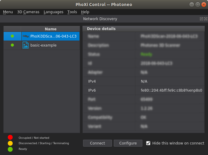
Note: To configure the network settings of a 3D sensor, open the PhoXi Control, go to the Network discovery, select the sensor and choose the option Configure at the bottom of the application window.
image3

2.3 Network interface

The Network section of the Network page serves for the configuration of the interface through which the vision controller connects to the Internet, the factory network, and other devices on the network. Read about Remote access methods to find out more about ways of remote control of the Studio.

The interface can be configured to use an arbitrary static IPv4 address (manual IPv4 method) or to run a DHCP client (automatic IPv4 method).

Manual
This option is used when connecting directly to a remote device or to a local network without a DHCP server.
Direct connection to the remote device
Configure the network interface of the vision controller and the remote device to be on the same subnet.
The vision controller will be accessible from the remote device on the IP address of the network interface.
Connection to a local network
Configure the network interface of the vision controller so that the IP address is within the range of the local network. If a DHCP server is running on the network, ensure the IP address is outside the range from which the DHCP server assigns IP addresses to connected DHCP clients.
The vision controller will be accessible from any device on the same local network on the IP address of the network interface.
If the local network is connected to the Internet, the vision controller will also have access to it (provided the network interface has been configured properly - correct Gateway and optionally the DNS server).

Automatic

Note for remote access:
For the VNC and TeamViewer over LAN, it is recommended to use a static IP in order to make sure to have the vision controller always accessible on the same IP address. Alternatively, it is possible to use this option (Automatic) but it is recommended to use DHCP reservation to make sure the DHCP server always assigns the vision controller the same IP address.
This option is used when connecting to a local network with a DHCP server.
The parameters of the interface are non-editable - they are obtained from the DHCP server.
The vision controller will be accessible from any device on the same local network on the IP address assigned to it by the DHCP server.
If the local network is connected to the Internet, the vision controller will also have access to it.

3 Troubleshooting network connections

When the Save button is pressed on a specific section of the Network page, the settings within this section are applied to the host system (Ubuntu) network settings. It is not possible to amend the network settings through the Ubuntu network panel.

3.1 Robot interface

Communication between the vision controller and the robotic controller uses two channels - the Action Request Communication Channel and the Robot State Communication Channel (Bin Picking Studio only). If the network configuration is incorrect it is possible to have one (or both) of these channels non-working.

To quickly check the network reachability of the robotic controller from the vision controller, the Test connection button located on the Robot interface subsection of the Network page can be used. The connection check can result in:

  • Available connection

  • Unreachable connection state, possible causes:

    • wrong network configuration

    • the robotic controller is turned off (connection is not established)

    • cable is unplugged/damaged

On the Deployment page there are two indicators informing about the current state of the robot connection status:

  • Action Request Client - status of the connection between the Action Request Server and Action Request Client (the Action Request Communication Channel). It can be in two different states:

    • **  CONNECTED  ** - the Action Request Client is connected to the Action Request Server and can send requests.

    • **  DISCONNECTED  ** - the Action Request Client is not connected to the Action Request Server, the server is waiting for a new connection. If you are encountering connection problems, please check:

      • Is the robotic controller reachable? Please use the Test connection button on the Network page.

      • Are you connecting to the correct IP address (Robot interface IP address) in the robotic program?

      • In the case of custom port usage, have you applied the same changes both on the Network page and in the main robotic program?

  • Robot State Server (Bin Picking Studio only) - status of the connection between the Robot State Server and the Robot State Client (the Robot State Communication Channel). It can be in two different states:

    • **  CONNECTED  ** - the Robot State Client is connected to the Robot State Server and periodically receives robot state data - current joint positions and TCP pose.

    • **  DISCONNECTED  ** - the Robot State Client is not connected to Robot State Server, the client repeatedly tries to connect to the server. If you are encountering connection problems, please check:

      • Is the robotic controller reachable? Please use the Test connection button on the Network page.

      • Is the Robot State Server on the robotic controller running?

      • In the case of custom port usage, have you applied the same changes both on the Network page and in the robotic program of the Robot State Server?

3.2 Sensor interfaces

A Photoneo 3D sensor associated with a vision system gets automatically connected when the following processes are started:

  • Teaching gripping point

  • Localization configuration

  • Calibration

  • Deployment

All processes except for the Deployment execute a single attempt to connect to the sensor. If the connection is successfully established, the process is started, otherwise, an error is raised.
When the Deployment is starting, each vision system attempts to connect to the associated sensor several times. If none of these attempts are successful, a FATAL error message is raised.

On the Deployment page, there’s a status indicator for each vision system informing about the current state of the connection to the associated 3D sensor, Each indicator carries the ID of the vision system it belongs to:

  • **  1  ** - the sensor associated with vision system 1 is connected

  • **  2  ** - the sensor associated with vision system 2 is not connected

When a valid connection to a Photoneo 3D sensor is suddenly interrupted during the deployment a FATAL error message is raised.

Once connected to a sensor interface of the vision controller, either directly or through a network switch, a Photoneo 3D sensor should appear in the PhoXi Control in the list of the available sensors (window Network discovery). Should it happen that the sensor is not showing up in the list, please contact support@photoneo.com.

As mentioned in the sensor interface network configuration, each 3D sensor is assigned a fixed IPv6 link-local address which is preferred over IPv4 address when the connection between the vision controller and the sensor is established. Should the IPv6 connection fail, the IPv4 address is used. Therefore, it is recommended to have a valid IPv4 network configuration.
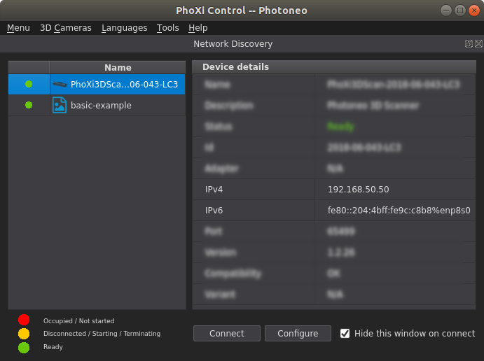
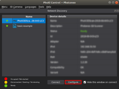
To check whether the sensor has a valid IPv4 address assigned, open the PhoXi Control and select the sensor. There should be a valid IP address in the field IPv4.
image4

Valid network configuration:

Sensor interface
IPv4 method

3D sensor IP assignment type

3D sensor IPv4 field

Note

Manual - Static IP (DHCP server OFF)

Manual - Static IP

The IP address configured by the user

Recommended network configuration. The sensor interface IP address and the 3D sensor IP address are on the same subnet.

Manual - Static IP (DHCP server ON)

Automatic - DHCP client

An IP address in range 192.168.101.2 - 192.168.101.255

Valid network configuration.

Manual - Static IP (DHCP server OFF)

Automatic - DHCP client

An IP address in format 169.254.x.x

Unrecommended network configuration. The 3D sensor was assigned an IP via Zeroconf technology. This connection type might be unstable.

In case the IPv4 field shows N/A, the network configuration is invalid - the sensor interface IP address and the 3D sensor IP address are not on the same subnet. The issue must be fixed.
image5

Invalid network configuration:

Sensor interface
IPv4 method

3D sensor IP assignment type

Troubleshooting

Manual - Static IP (DHCP server OFF)

Manual - Static IP

Change the IP address(es) to be on the same subnet.

Manual - Static IP (DHCP server ON)

Manual - Static IP

Turn off the DHCP server on the sensor interface and configure a static IP address on the same subnet as the IP address of the 3D sensor.

Alternatively, configure the 3D sensor to use DHCP as IP assignment type.