Integration Guide Yaskawa LS 1.5
Integration guide for Yaskawa Robots with Locator Studio version LS 1.5.
1. Robot Controller Setup
1.1 IP Configuration
Start the Robot Controller in a Maintenance Mode by holding the Main Menu button while turning the main switch on. You should hear a short beep during the boot. The Maintenance Mode screen is shown in the figure below:
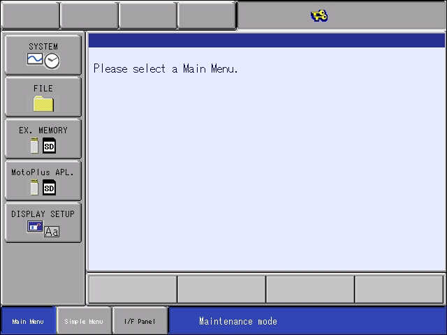
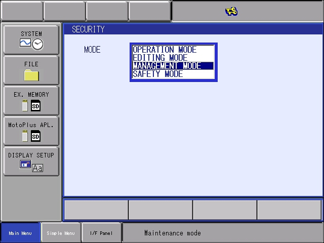
Switch the Security Level from Editing to Management Mode. Browse to System Security

And select Management Mode from the list:
The password for accessing Management Mode is 9999 9999 9999 9999 (16 x 9 without spaces):
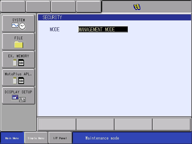
Note
the three keys in the top status bar - this indicates that - Management Mode is Active.
In order to configure the IP address of the Robot Controller, browse to System ? Setup ? Option Functions
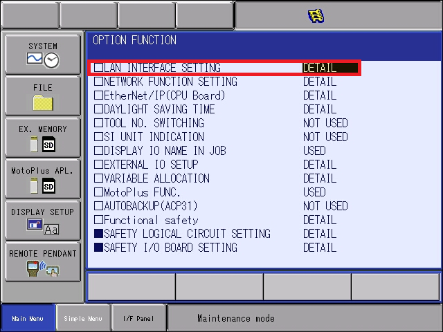
Select LAN Interface Setting to enter the Network Configuration pane:
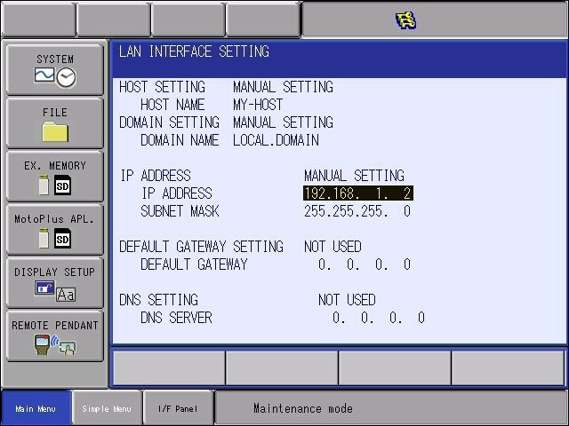
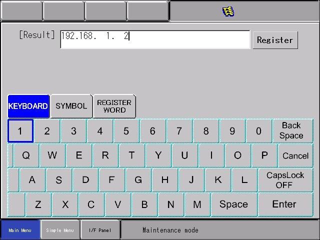
Select Manual Setting for LAN2 Port and amend the IP Address to meet your network requirements:
Note
It is recommended to plug the Ethernet cable into the LAN2 port.
Note
Subnet Mask 255.255.255.0 equals 24 bit subnet mask representation. See this table for more combinations: https://dnsmadeeasy.com/support/subnet
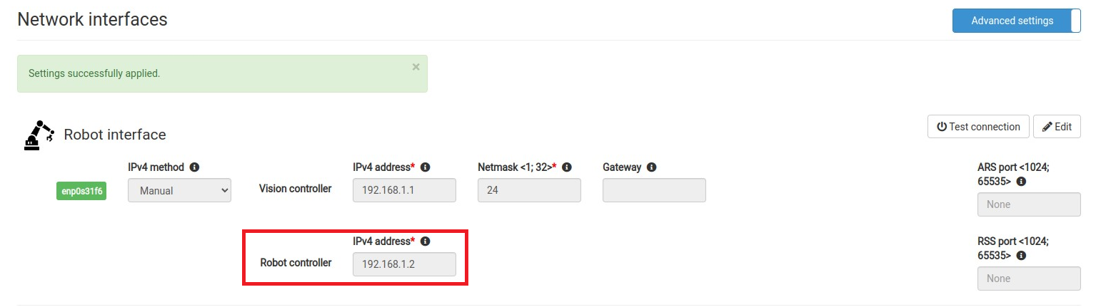
An example of matching Network configuration on Vision Controller side
Vision Controller IPv4 Address: 192.168.1.1 / 24
Robot Controller IPv4 Address: 192.168.1.2 / 24 (as configured in previous step)
1.2 Enabling MotoPlus functionality
If MotoPlus functionality has not been already enabled on Robot Controller, browse to System → Setup → Option Functions
Switch MOTOPLUS Func State from NOT USED to USED.
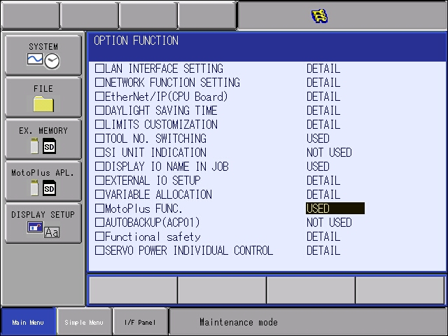
The MotoPlus APL icon should now become visible on the left pane.
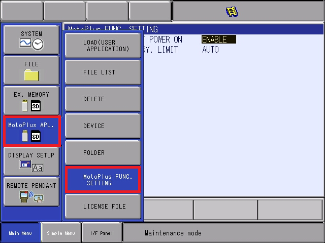
Enter the MotoPlus Func. Settings:
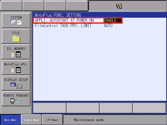
Enable the MotoPlus autostart option:
1.3 Loading of Motoplus Binary (.out)
The Photoneo Yaskawa Interface consists of
MotoPlus Binary - PhotoneoModule_LS_1.5.0.out
INFORM files - Request INFORM Jobs + Program INFORM Job Templates
Based on the type of your robot controller, use the .out file from the appropriate folder (DX100, DX200, FS100, YRC1000, YRC1000u) and make sure it is available at the root directory of USB Flash drive.
Load MotoPlus Binary using following steps:
Select MOTOPLUS Apl. Load (User Application)
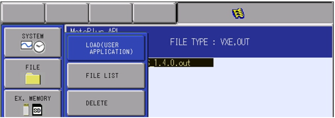
Select the PhotoneoModule_LS_1.5.0.out file and confirm Load. The Maintenance Mode section of the configuration process is now complete.
Note
Only single .out Photoneo binary can be uploaded at the same time. Check File List to make sure there is no other Photoneo MotoPlus binary uploaded. Restart the Robot Controller back into Normal Mode.
1.4 Loading of INFORM Jobs
Make sure all Inform jobs are available at the root directory of the USB flash drive. Browse to Ex. Memory Load and hit Edit Select all to select available JOBS from INFORM folder:
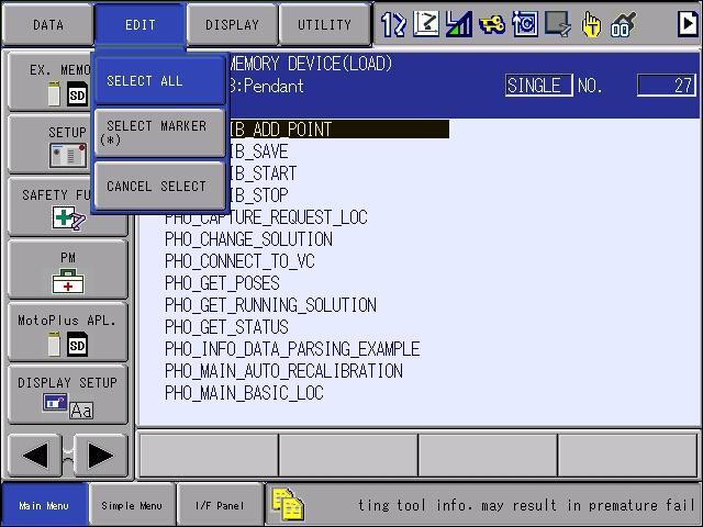
Hit Enter to start the transfer:
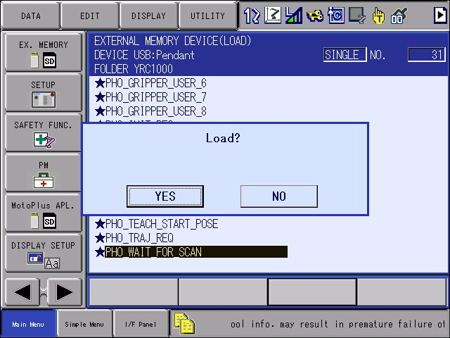
All JOB files should now be available in the Robot Controller.
1.5 Loading of VARNAME.dat
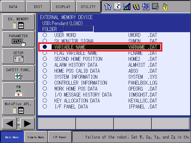
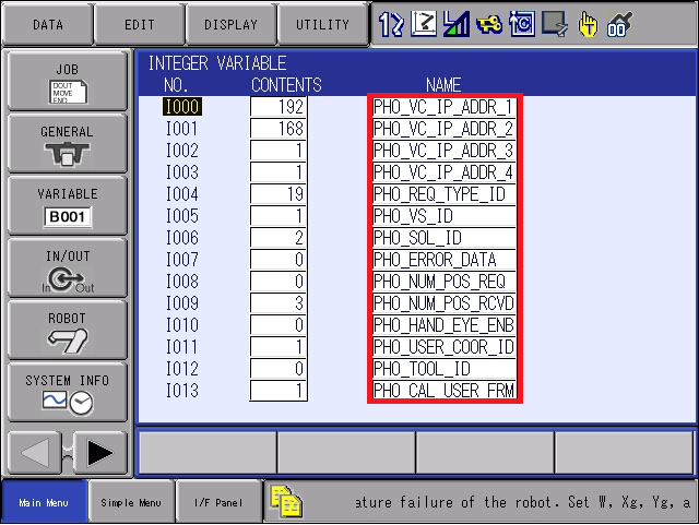
In order to populate names for variables used by Photoneo, VARNAME.dat system file is provided together with INFORM jobs. Loading of this file will erase all existing names and populate the ones used by Photoneo.
Make sure VARNAME.dat is available at the root directory of the USB drive. Go to Ex. Memory Load
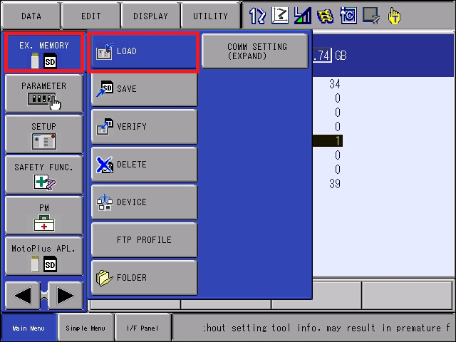
Select System Data
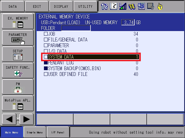
Select VARIABLE NAME ? VARNAME.DAT file from the list, hit Enter button and confirm Loading.
After executing this operation, all variable comments will be erased and names of variables used by Photoneo will be populated (BYTE, INTEGER, POSITION, STRING).
1.6 Set IP address of Vision Controller on the Robot Side
As a next step we need to let Yaskawa Robot Controller know what is the IP address of Vision Controller as configured on the Locator Studio Network page. First 4 integer variables are used for this purpose:
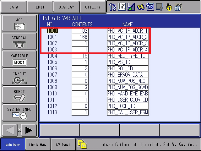
IP Address configured in first 4 Integer variables must match Vision Controller IP address as defined on LS Network page:

To confirm that the Robot Controller is physically connected to the Vision Controller and the Network is configured properly use the Ping feature from System Info ? Network Utility:
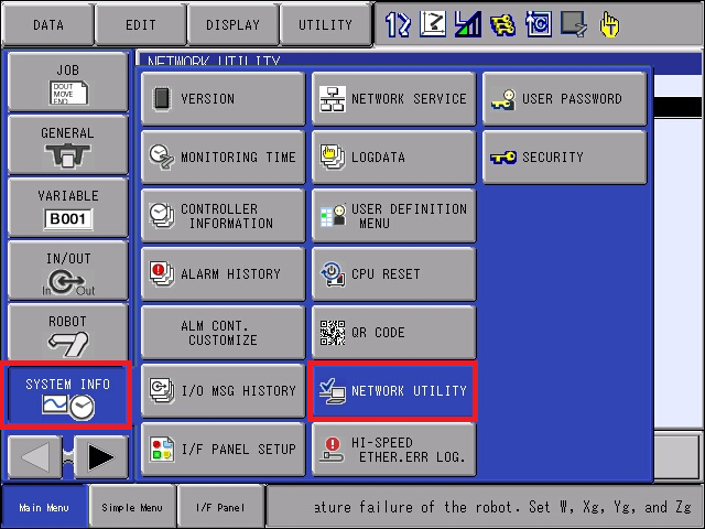
Type IP address of Vision Controller to Host field and hit Execute button:
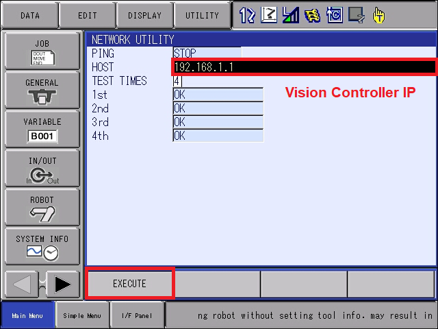
If a connection exists, Ping will return a “OK” message on all 4 attempts. You can also use the Test Connection button on the Photoneo Vision Controller Network page to Ping Yaskawa Robot from Photoneo Vision Controller.
Based on the result of Test Connection (ping command) Robot Available or Robot Unavailable is returned


If the robot is unavailable, please check cabling, network settings on both sides and try again, make sure ethernet cables are connected to proper ports and if there is a switch used, it is not blocking the connection.
1.7 USER COORDINATE setup
For Locator Studio solution types (Localization and Delayering) it is recommended to stick with the original Yaskawa Base frame as origin for both Calibration and Picking. Yaskawa Base frame origin sits at the intersection of J1 axis and J2 axis plane (see image below). In order to guarantee successful calibration and picking, User Coordinate 1 needs to have all values zeroed.
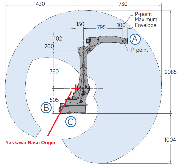
It is recommended to create a PHO_ZERO_OFFSET user coordinate frame to prevent this frame from being used later by robot programmers. In order to do so follow steps below:
Choose user frame - press Robot User Coordinate
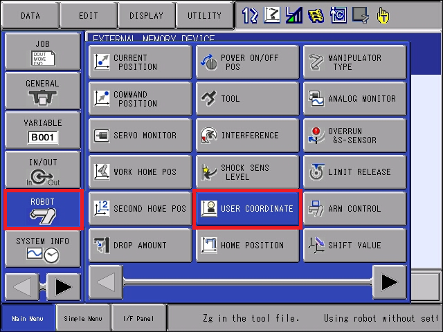
Select User Coordinate 1 from the list and name it PHO_ZERO_OFFSET.
In order to see coordinate values, select first frame and press Display Coordinate Data

Make sure all values are zeroed, Robot R1 is selected and the Basic Coordinate frame is set to BASE.

This configuration will make sure that there is a zeroed Yaskawa Base User Coordinate frame which is important for proper calibration and picking.
Note
Integer variable PHO_CALIB_USER_ID is reserved in the variable list but not used in this version of the module. Hardcoded value pointing to User Coordinate 1 is used instead. If this is causing issues in your application, please contact Help Center for a customized module version.
1.8 TOOL Frame
Note
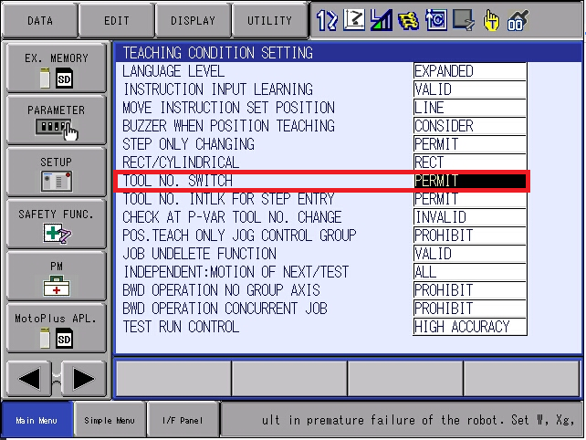
Tools are only visible if Setup ? Teaching Conditions ? Tool No Switch is Set To Permit.
Calibration TOOL - for calibration purposes Photoneo Locator Studio needs zeroed Tool Frame. By default TOOL 63 (the last one) is used under the assumption that it is all zeros. So as long as TOOL 63 is zeroed nothing needs to be changed in terms of coordinate values. It is recommended to give it a name to make sure the tool is not used later by robot programmers.
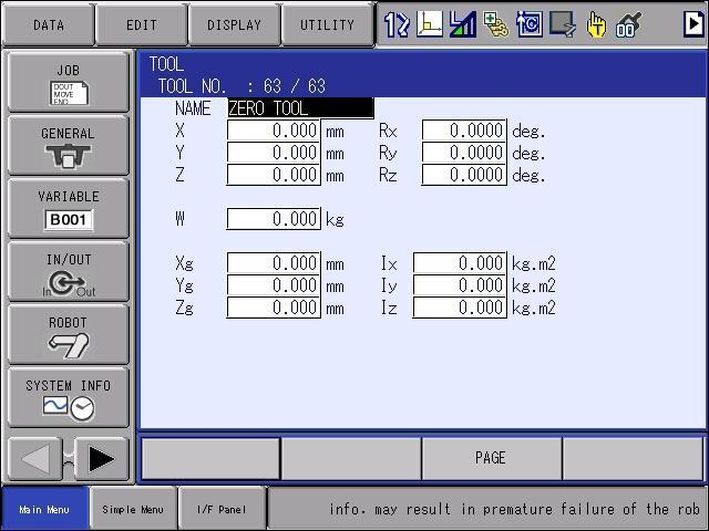
Picking TOOL - for picking purposes, use properly configured/calibrated Tool ID as you would use in normal robotic applications.

Note
Integer variable PHO_CALIB_TOOL_ID is reserved in the variable list but not used in this version of the module. Hardcoded value pointing to Tool ID 63 is used instead. If this is causing issues in your application, please contact Help Center for a customized module version.
2. Robot Module
2.1 Requests List
This section describes available API calls (Requests) supported by the Robot module. These procedures are intended for high-level control of the Locator Studio application from INFORM program:
INFORM Job |
Function |
Input |
Populates |
|---|---|---|---|
PHO_CALIB_ADD_POINT |
Add Calibration Point Request |
None |
I007 |
PHO_CHANGE_SOLUTION |
Change Solution Request |
I006 |
I007 |
PHO_START_SOLUTION |
Start Solution Request |
I006 |
I007 |
PHO_STOP_SOLUTION |
Stop Solution Request |
None |
I007 |
PHO_GET_RUNNING_SOLUTION |
Get Current Running Solution Request |
None |
I007, I006 |
PHO_SCAN_REQUEST_LOC |
Regular Scan Request |
I005 |
None |
PHO_WAIT_FOR_SCAN |
Counterpart for Scan and Capture Request |
None |
I007 |
PHO_GET_POSES |
Request Cartesian Poses of all localized objects |
I005 |
I007, P011-P109 |
PHO_GET_STATUS |
Get Vision System Status - Number of Localized, Pickable objects, Vision System Status - Running/Finished |
I005 |
I007, I016, I017, I018 |
PHO_CALIB_START |
Start Calibration Request |
I005, I006 |
I007 |
PHO_CALIB_STOP |
Stop Calibration Request |
None |
I007 |
PHO_CALIB_SAVE |
Save Calibration Request at the end of Calibration |
None |
I007, I015, P010 |
PHO_CAPTURE_REQUEST_LOC |
Capture Scan Request - for meshing, doesn’t initiate localization |
I005, I031* |
I007 |
PHO_REUSE_SCAN_REQUEST_LOC |
Reuse last captured scan for localization on different Vision System |
I005 |
I007 |
PHO_CHANGE_BBOX |
Request to change bounding box |
I005, I032 |
I007 |
PHO_COM_CHECK |
Request to check communication |
None |
I007 |
I005 Vision System ID, I006 Solution ID, I007 Error Data, I015 Calib Accuracy, I016 Num of Localized, I017 Num of Pickable, I018 VS Running/Finished, I031 *Capture Gap Only used in Dynamic Meshing, I033 - Bounding Box ID, P010 Calibration Result Pose, P011-P109 - Cartesian Object Poses
2.2 INFORM Connection Procedures
The following procedure is used for connection and disconnection of the Motoplus backend from Vision Controller.
INFORM JOB |
Description |
|---|---|
PHO_CONNECT_TO_VC |
INFORM Job used to notify MotoPlus backend to establish connection to Vision Controller |
2.3 INFORM Examples List
There are several INFORM Example Templates available in LS 1.5 module that demonstrate how to properly use requests listed in section 2.1 for various use cases:
INFORM Example |
Description |
|---|---|
PHO_MAIN_CALIBRATION PHO_MAIN_CALIBRATION_HAND_EYE |
Template for Calibration procedure, first calibration of Vision System must be started and confirmed manually by the user on the Vision Controller side. Calibration procedure requires proper USER COORDINATE configuration as described in chapter 1.7. Teach all 9 poses required for calibration. If communication with the vision controller is established by PHO_CONNECT_TO_VC then PHO_CALIB_ADD_POINT request calls feed vision controller with current robot pose for each added point. If communication cannot be established, then it is possible to add robot poses manually on the vision side by typing values from the current robot pose from the pendant. General rule of thumb is that Calibration Error should be below 3mm. If it is more, then there is usually some systematic error (Robot not reporting proper pose, or calibration ball moved during transitioning between poses etc). If calibration error is below 3mm, save calibration on the Vision Controller side and quit calibration. |
PHO_MAIN_AUTO_RECALIBRATION |
After the first calibration is successful and automatic recalibration is allowed in Vision System settings, you can run automatic recalibration from the robot without even touching the vision system. Calibration ball or marker pattern must remain in the same spot as during initial calibration.This example adds PHO_CALIB_START, PHO_CALIB_SAVE and PHO_CALIB_STOP to the original PHO_MAIN_CALIBRATION example. |
PHO_MAIN_BASIC_LOC |
Very basic example for a statically mounted scanner where the user can see how to initialize a system, send scan request, get poses request, receive targets and execute paths. The provided example also demonstrates error handling - PHO_SCAN_REQUEST and PHO_GET_POSES return error value to I007 - PHO_ERROR_DATA. Make sure you manually set Start and End positions in PHO_PICK_OBJECTS_LOC prior running this INFORM job (Chapter 3.1) and fill out blank gripper commands (Chapter 3.2) |
PHO_MAIN_BASIC_LOC_HAND_EYE |
Same as PHO_MAIN_BASIC_LOC but for a Hand Eye mounted scanner. The only difference is scanning pose is different than for the static mount and I010 - PHO_HAND_EYE_ENABLE switch is turned ON |
PHO_MAIN_BASIC_LOC_MULTI_VS |
Same as PHO_MAIN_BASIC_LOC but with switching between two Vision Systems. Integer variable I005 PHO_VS_ID is important in this case. Value in this variable controls which Vision System will be triggered or requested for poses. The first pick in the loop is executed using Vision System 1 and the second pick in the loop is executed using Vision System 2. |
PHO_MAIN_BASIC_LOC_SOL_SWITCH |
Same as PHO_MAIN_BASIC_LOC but demonstrates use of all Solution Switching related requests. Integer variable I006 PHO_SOL_ID is important here as it defines what solution will be activated with the next PHO_START_SOLUTION or PHO_CHANGE_SOLUTION requests. |
PHO_MAIN_BASIC_LOC_CHANGE_BBOX |
Same as PHO_MAIN_BASIC_LOC but demonstrates use of Bounding Box switching request. Besides I005 PHO_VS_ID Integer variable I032 PHO_BBOX_ID is important here as it defines what bounding box will be activated with the next PHO_CHANGE_BBOX request |
PHO_MAIN_BASIC_LOC_REUSE_SCAN |
Same as PHO_MAIN_LOC_MULTI_VS but instead of sending regular scan requests, the new request called PHO_REUSE_SCAN_REQUEST is demonstrated here. This request is useful in situations where the scene hasn’t changed since the last scan was triggered but the user wants to repeat localization with a different configuration (searching for different objects, in different bounding boxes or with different settings). Scan for VS1 is regular and scan for VS2 is then reused from scan for VS1. Integer variable I005 PHO_VS_ID is used for reuse scans in the same fashion as for regular Vision System switching. |
PHO_MAIN_LOC_MESHING_STATIC |
An example of how to stitch multiple scans before initiating localization. It is useful for more complicated scenes or large objects. This example demonstrates a static approach with a robot stopping in each scanning position and triggering/capturing scan. B004 PHO_MESH_DYNAMIC needs to be set to 0. During the meshing process, each PHO_CAPTURE_REQUEST scan must be followed by PHO_WAIT_FOR_SCAN to finalize the request. When done with capturing, trigger regular PHO_SCAN_REQUEST_LOC to initiate localization - this request doesn’t trigger actual scan, it only initiates localization process. The total number of scans should be less than 10. |
PHO_MAIN_LOC_MESHING_DYNAMIC |
Similar to PHO_MAIN_LOC_MULTIVIEW_STATIC but in this case capturing happens while the robot is continuously moving. LS integrates Photoneo Instant Meshing technology in combination with Parallel structured light technique provided by Motion Cam 3D. Important Flags and Variables: B004 PHO_MESH_DYNAMIC, B005 PHO_MESH_STARTED, I031 PHO_CAPTURE_GAP. This example demonstrates how to initiate a capturing procedure, allowing Motion Cam to trigger scans with mutual delays set by I031 PHO_CAPTURE_GAP while moving the robot through predefined waypoints. B004 - PHO_MESH_DYNAMIC must be set to TRUE to activate Dynamic Meshing mode, and I031 PHO_CAPTURE_GAP should be set to approximately 100-500 ms to throttle the scanning and not oversaturate system with scans. Robot position during first scan is essential for proper orientation of the final point cloud therefore robot motion is blocked by Photoneo interface until B005 - PHO_MESH_STARTED is set to 1 by Motoplus backend after first scan is received and reset after the last scan is captured. Only the last PHO_CAPTURE_REQUEST in this dynamic case is followed by a PHO_WAIT_FOR_SCAN request. Regular PHO_SCAN_REQUEST_LOC must be sent at the end of capturing to initiate localization. This scan doesn’t flash any light, it only starts the localization process. The scanning trajectory should be smooth without large rotations and the scanned area needs to be in the field of view all the time to avoid losing track. The total number of scans should be less than 60. |
2.4 INFORM Picking Procedures
The following procedure is used for picking and placing of all objects received from the Vision Controller. This is just an example on how to iterate through received targets and control robot movements. Local Start and End points that need to be touched up in PHO_PICK_OBJECTS_LOC before running the main program. Feel free to copy and modify if needed.
INFORM JOB |
Description |
|---|---|
PHO_PICK_OBJECTS_LOC |
INFORM Job for picking and placing targets received from Vision Controller. |
2.5 BYTE Variables
This version of the LS module uses following 6 Byte variables:
BYTE Var |
Description |
Set by |
|---|---|---|
B000 PHO_CONNECT_VC |
This flag is set from INFORM Job to notify MotoPlus backend to establish connection to Vision Controller |
user |
B001 PHO_CONNECTED |
This flag is set internally by MotoPlus backend after connection to action server running on Locator Studio side is established and reset after session is terminated |
system |
B002 PHO_NEW_REQ |
This flag is set by request INFORM Job to notify MotoPlus backend that a new request has been initiated by the user. MotoPlus backend resets this flag after it gets processed on its side |
user |
B003 PHO_REQ_FINISHED |
This flag is set by the MotoPlus backend to notify INFORM that a response for a recently submitted request has been received. The INFORM side resets this flag right after. |
system |
B004 PHO_MESH_DYNAMIC |
This flag activates Dynamic meshing mode. It must be set to TRUE before the first PHO_CAPTURE_REQUEST request and reset to FALSE right after reaching the final meshing waypoint to stop scanning sequence. Set to FALSE is using Capture in Static mode |
user |
B005 PHO_MESH_STARTED |
This flag is set by MotoPlus backend to notify INFORM that first scan of the meshing sequence has arrived and predefined capture trajectory can be started on the INFORM side. |
system |
2.6 INTEGER Variables
This version of the LS module uses following Numeric Variables:
Variable |
Description |
Set by |
|---|---|---|
I000 PHO_VC_IP_ADDR_1 |
First octet of IP address of Vision Controller |
user |
I001 PHO_VC_IP_ADDR_2 |
Second octet of IP address of Vision Controller |
user |
I002 PHO_VC_IP_ADDR_3 |
Third octet of IP address of Vision Controller |
user |
I003 PHO_VC_IP_ADDR_4 |
Fourth octet of IP address of Vision Controller |
user |
I004 PHO_REQ_TYPE_ID |
Set by every request INFORM job to notify MotoPlus which request to process |
system |
I005 PHO_VS_ID |
Variable to control which Vision system ID is going to be used for next request |
user |
I006 PHO_SOL_ID |
Variable to control which Solution ID is going to be used for next request |
user |
I007 PHO_ERROR_DATA |
Populated as a result of request handling. See error table for error code descriptions |
system |
I008 PHO_NUM_POS_REQ |
Number of targets requested by PHO_REQ_GET_POSES request |
user |
I009 PHO_NUM_POS_RCVD |
Number of received targets populated by PHO_REQ_GET_POSES request |
system |
I010 PHO_HAND_EYE_ENB |
Switch between Static (0) and Hand Eye mode (1) |
system |
I011 PHO_USER_COOR_ID |
Register controlling which USER Frame is used for TCP reporting |
user |
I012 PHO_TOOL_ID |
Register controlling TOOL frame used for TCP reporting |
user |
I013 PHO_CAL_USER_FRM |
Register controlling which USER Frame is used for calibration |
user |
I014 PHO_CAL_TOOL_FRM |
Register controlling UTOOL is used for TCP reporting (Not used if Hand Eye is disabled) |
user |
I015 PHO_CALIB_ERROR |
Calibration error from automatic recalibration in milliradians |
system |
I016 PHO_NUM_OF_LOC |
Number of already localized objects - gets populated by Get Status response |
system |
I017 PHO_NUM_PICKABLE |
Number of pickable objects - gets populated by PHO_REQ_GET_STATUS request |
system |
I018 PHO_VS_CUR_STAT |
Current Vision system status - gets populated by PHO_REQ_GET_STATUS request |
system |
I019 PHO_RESERVED |
Reserved for internal iteration variable |
system |
I020 PHO_RESERVED |
Reserved for internal iteration variable |
system |
I021 PHO_RESERVED |
Reserved - aligns with BPS PHO_TOOL_INV (not used in LS) |
system |
I022 PHO_RESERVED |
Reserved - aligns with BPS PHO_GRIPPING_PT_ID (not used in LS) |
system |
I023 PHO_RESERVED |
Reserved - aligns with BPS PHO_GRIPPING_PT_INV (not used in LS) |
system |
I024 PHO_DIMENSIONING_X |
Dimensioning X of current localized object (AI-based solutions, same as Info Data op 4) |
system |
I025 PHO_DIMENSIONING_Y |
Dimensioning Y of current localized object (AI-based solutions, same as Info Data op 5) |
system |
I026 PHO_DIMENSIONING_ROT_Z |
Dimensioning Rot Z of current localized object in degrees (AI-based solutions, same as Info Data op 6) |
system |
I027 PHO_NN_LABEL |
NN Label (Neural Network object class label, AI-based solutions, same as Info Data op 7) |
system |
I028 PHO_MAX_Z_HEIGHT |
Max Z Height of current localized object (same as Info Data op 8) |
system |
I029 PHO_TILT |
Tilt angle of current localized object in milliradians (same as Info Data op 9) |
system |
I030 PHO_INFO_DATA_10 |
Reserved - not populated by current info operations (Info Data op 10 dispatches to PHO_CALIB_ERROR I015) |
system |
I031 PHO_CAPTURE_GAP |
Controls delay in milliseconds between consecutive scans in Instant Meshing mode |
user |
I032 PHO_BBOX_ID |
Controls which Bounding box ID will be used for next request |
user |
I034 PHO_RUNNING_SOLUTION |
Currently running Solution ID (populated by Get Running Solution request) |
system |
2.7 POSITION Variables
P000 - P007 are free for customers.
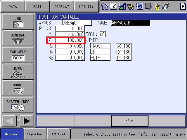
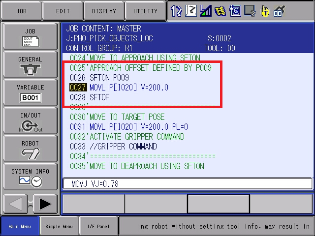
P008 and P009 are CART poses used in the PHO_PICK_OBJECTS_LOC routine for Approach and Deapproach offsets. These variables should only have Z value set in order to achieve proper behaviour using SFTON shift operation. For example Approach pose shown below will set approach point 100mm above target pose if used within SFTON- SFTOF.
P010 is reserved for Calibration Save request and holds Calibration pose after automatic recalibration.
P011 - P100 are reserved for Cartesian Poses received from the Vision Controller.
This version of the LS module uses following 120 Position Variables:
Variable |
Repre |
Description |
Set by |
|---|---|---|---|
P000 |
Free for customer |
user |
|
… |
Free for customer |
user |
|
P007 |
Free for customer |
user |
|
P008 |
CART |
Approach pose for PHO_PICK_OBJECTS_LOC (feel free to change code and use) |
user |
P009 |
CART |
Deapproach pose for PHO_PICK_OBJECTS_LOC (feel free to change code and use) |
user |
P010 |
CART |
Variable to store Calibration Pose from automatic recalibration invoked by PHO_CALIB_SAVE request. This pose can be useful for various checks or point reteaching especially in hand eye applications |
system |
P011 |
CART |
Variable to store Cartesian Results received from Vision Controller |
system |
… |
CART |
Variable to store Cartesian Results received from Vision Controller |
system |
P100 |
CART |
Variable to store Cartesian Results received from Vision Controller |
system |
3. Runtime
If the solution is configured, all Vision Systems are calibrated and all previous steps have been carried out, it is time to complete the final steps on the robot side and finally run the MAIN program on the robot.
3.1 Teaching Start and End Poses in PHO_PICK_OBJECTS_LOC
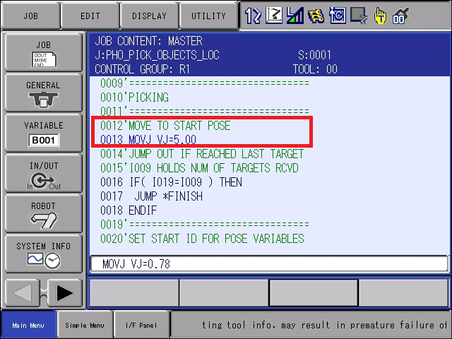
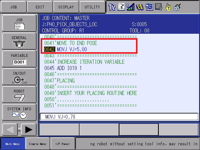
Start and End poses in PHO_PICK_OBJECTS_LOC define the first and last bin waypoints for pick and must be touched up before running the main picking procedure.
In order to touch up the point, move the program pointer to the MOVJ line, hit start Servo On Ready, jog robot to start position and hit Modify followed by Enter button to confirm new pose value.
Repeat the same for End Pose.
3.2 Gripper commands
Locator Studio Solution doesn’t control gripper commands so use regular DOUT or other IO related commands to control gripper actions in Grasp and Drop points.
3.3 Touch up local MOVJ positions
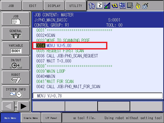
If you are going to use existing PHO_MAIN templates, scroll through the program and check for existing MOVJ commands and make sure the robot is in proper position during scanning (Out of scanning volume for statically mounted sensors or above the bin with hand eye carried).
3.4 Runtime Prerequisites
Final pre deployment check before running picking interface from the robot side
Make sure that:
Solution is properly configured on the Vision Controller side
Network Setup on Robot Side is completed and ping works in both directions
All Vision Systems defined in solution are calibrated
Start and End Pose in PHO_PICK_OBJECTS_LOC touched up
All local poses in MAIN Job you are about to run have been touched up properly
Gripper procedures are prepared and working
3.5 Running MAIN INFORM Job
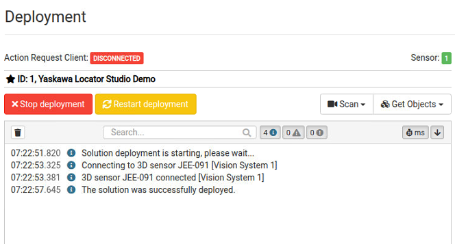
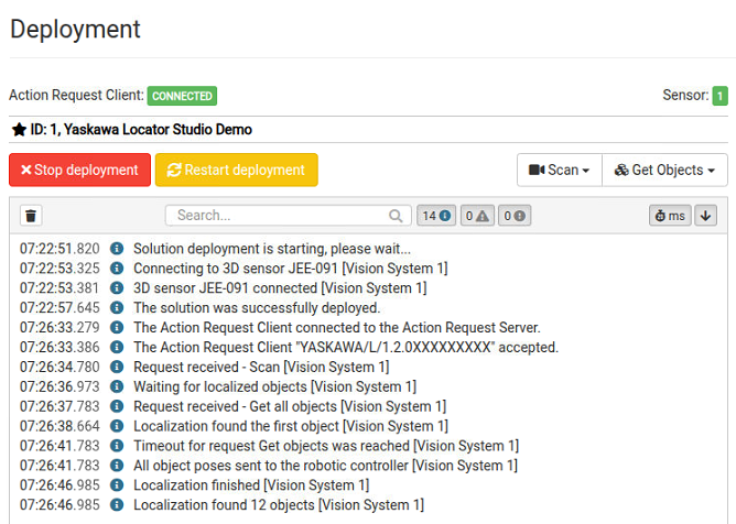
Deploy your solution. The Action Request Client (Robot) status on the Deployment page should be DISCONNECTED – from the Action Request Server, if the communication hasn’t been established yet.
Note
. It is strongly recommended to TEST START the application first before deploying to Auto.
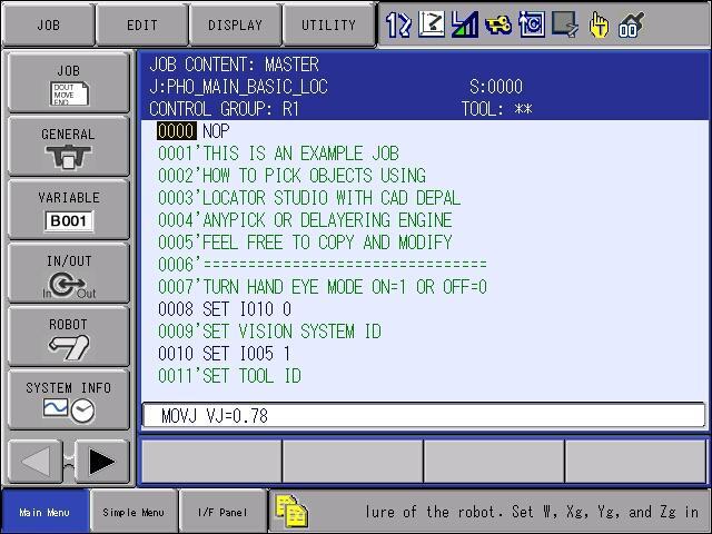
Using Select button navigate to program you want to run, in this case PHO_MAIN_BASIC_LOC.JBI template:
Hold Interlock and Test Start keys to test start the program. If connection has been established properly you will see Action Request Client turn to CONNECTED. At this point the sensor should capture the first scan and localization should start localizing objects.
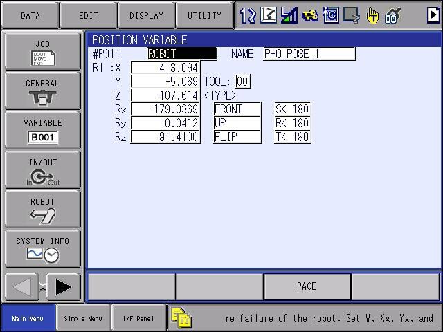
If there is a pickable object in the scene and the trajectory for the first object has been received by the robot controller, the robot should start moving towards the first object. You can check P011 and higher to see if these Position variables have been populated with joint data.
If everything looks fine, keep moving the robot towards the first target and check if the path is correct. At this point if the robot is too far from the object or pushes the object too deep, then make modifications on Picked object page by adjusting origin offset or change TCP configuration on the robot side
4. Error handling
If an error occurs during the execution of a request, the error value is stored in the variable I007 PHO_ERROR_DATA. All PHO_MAIN templates demonstrate basic error handling after PHO_SCAN_REQUEST and PHO_GET_POSES but if more specific handling is needed, it can be implemented additionally. Error codes with their description and troubleshooting can be found here.
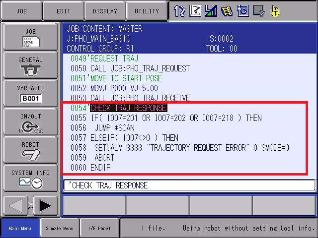
An example of Error Handling in TP after PHO_GET_POSES request: