Integration Guide Techman LS 1.5
Integration guide for Techman Robots with Locator Studio version LS 1.5.
1. Robot Controller Setup
1.1 Initial Setup and Configuration
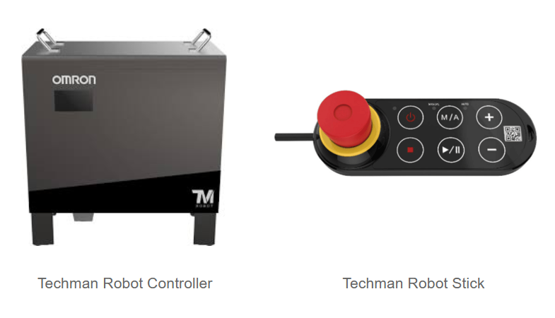
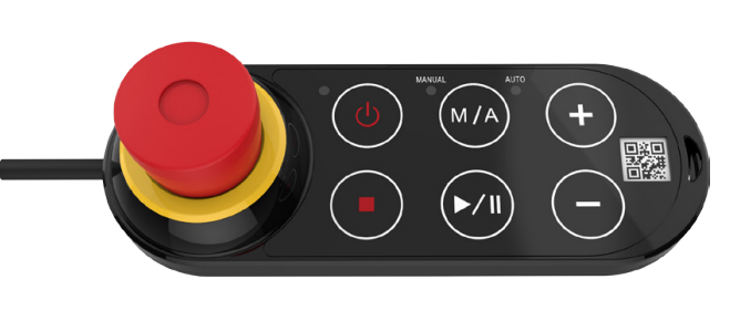
For engineers and technicians new to the Techman Robot platform, the initial setup of a locator application can present a number of challenges. This is particularly true in cases where the hardware package does not include a monitor-based pendant. Techman robots are typically shipped with “Robot Sticks,” which, while effective for basic runtime control, lack the full range of functionalities found in traditional robot pendants. Please refer to the image below for a visual depiction of the Robot Stick.
To initiate the commissioning process, it is essential to first establish a direct user interface with the robot controller. This is accomplished by connecting an HDMI monitor, a USB keyboard, and a mouse to the designated ports on the controller box. This local interface provides the necessary access to view the current system configuration and perform initial modifications, the most critical of which is the setup of the network interface. While this manual will leverage the TMFlow software for all subsequent commissioning procedures, the initial configuration of the controller’s IP address is a fundamental prerequisite that must be performed through this direct connection method.
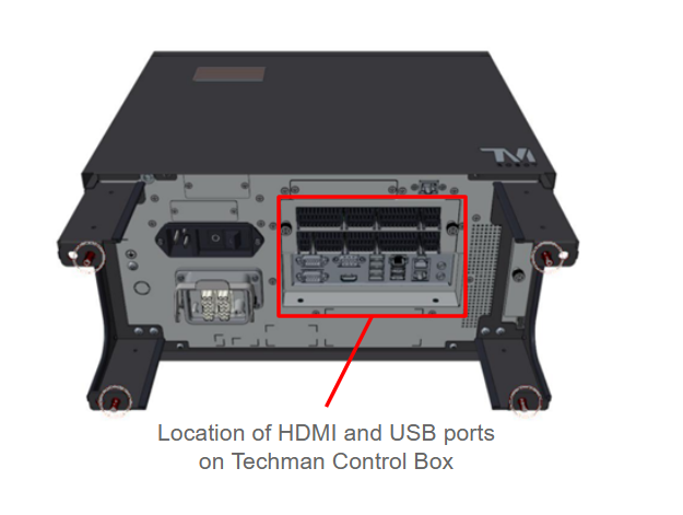
Using an external monitor along with a keyboard and mouse, you gain direct console access to the robot’s operating system. This access is necessary for configuring the network parameters required to establish a remote connection with the TMFlow application running on your PC.
1.2 Network Configuration
There are multiple Ethernet ports to choose from on Techman Control Box, and it is up to the user which port is selected for communication, in this tutorial we will use Port 2 for communication with Photoneo Vision Controller.
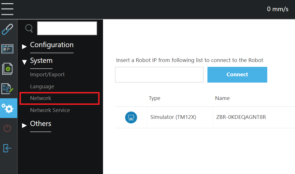
In order to change IP config, click Menu -> Settings -> System -> Network.
Select Static IP Address as the network method and type IP address and Subnet Mask for Robot Controller. Configuration used in this manual is 192.168.1.2 and 255.255.255.0.
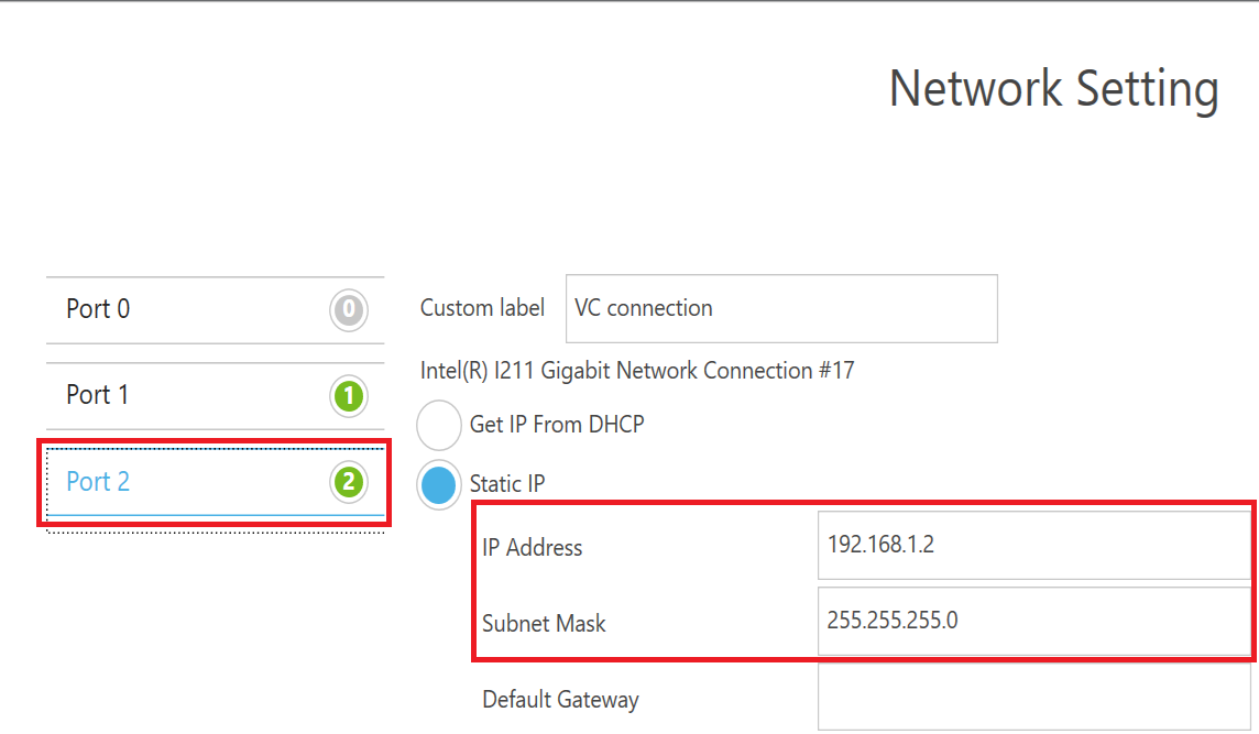
Click the Save button to confirm the changes.
Note
Subnet Mask 255.255.255.0 equals 24 bit subnet mask representation. See this table for more combinations: https://dnsmadeeasy.com/support/subnet
An example of matching Network configuration on Vision Controller side
Vision Controller IPv4 Address: 192.168.1.1 / 24
Robot Controller IPv4 Address: 192.168.1.2 / 24 (as configured in the previous step)
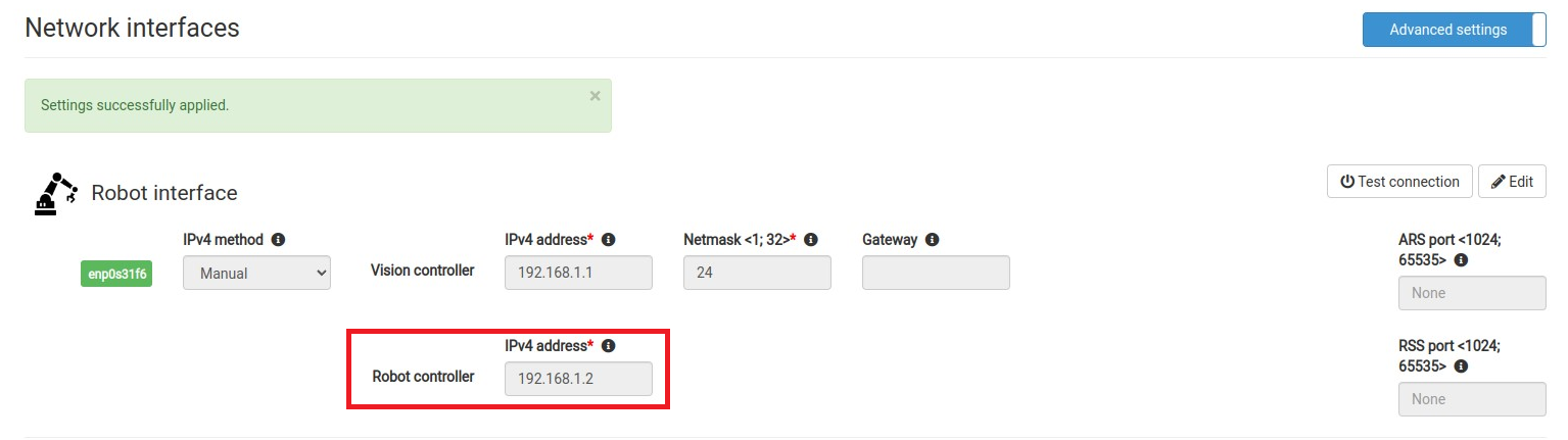
You can also use Test Connection button on Photoneo Vision Controller Network page to ping Techman Robot Controller from Photoneo Vision Controller

Based on the result of Test Connection (ping command) you will get a Robot Available or Robot Unavailable message pop up. If the robot is unavailable, double check cabling and network configuration.

1.3 Second Network interface for PC and TMFlow connection
It is recommended to configure a second Ethernet port for remote access using the TMFlow application on a PC. In this tutorial we will use Port 1 for this purpose. To prevent network conflicts, assign this interface a static IP address on a different subnet than the one used by the main Photoneo Vision Controller.
For example, a valid configuration for this Port 1 would be:
IP Address: 192.168.100.1
Subnet Mask: 255.255.255.0
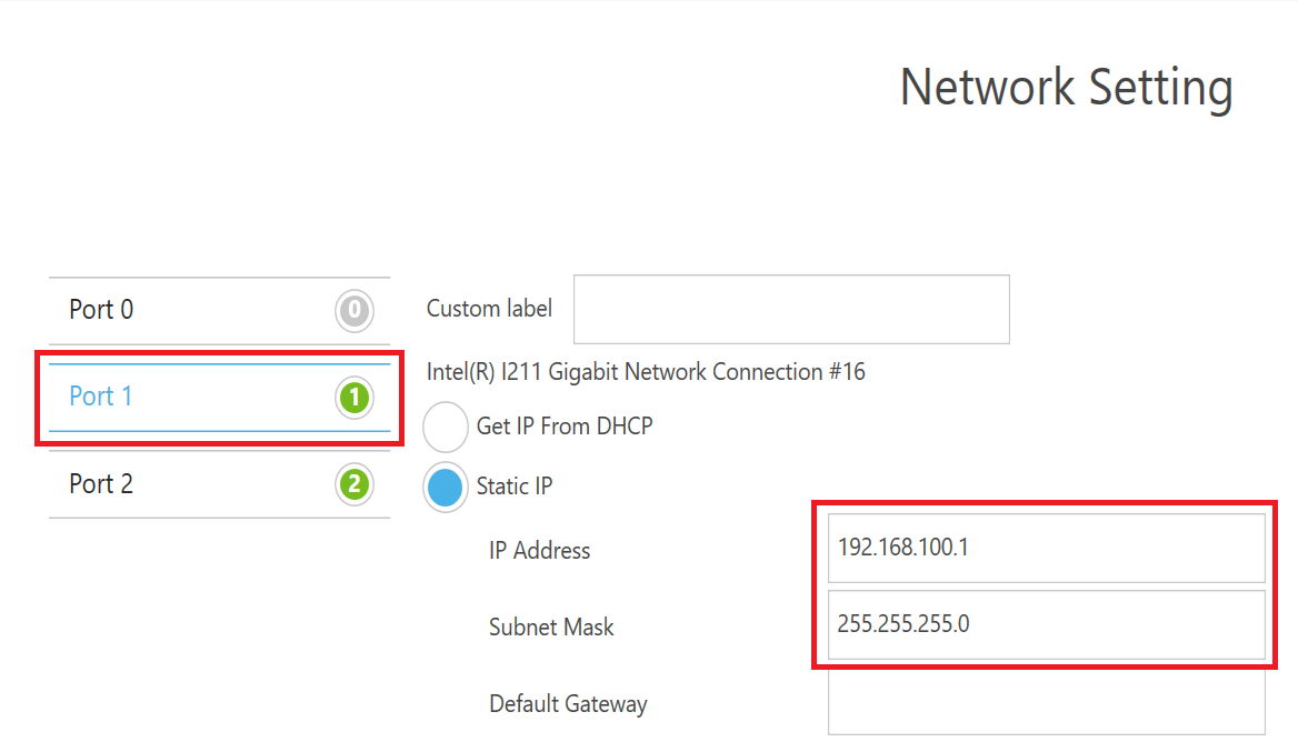
Before connecting to a real robot using TMFlow from your PC, make sure you configure your Ethernet port IPV4 address to be on the same subnet as the dedicated Techman port but of course with different IP.
Example IPv4 configuration of PC running TMFlow: 192.168.100.2 / 255.255.255.0
1.4 Tool TCP Setup
For Locator Studio, tool setup is more important than for Bin Picking Studio which is designed to operate with a zeroed tool and compensate for offset programmatically. General rule of thumb for Locator Studio is that all scanning and calibration must be done in RobotEndFlange frame, while all picking must be performed with a real tool - for the purpose of this tutorial we will be using tool named “CustomTool” with Z offset Z = 205mm.
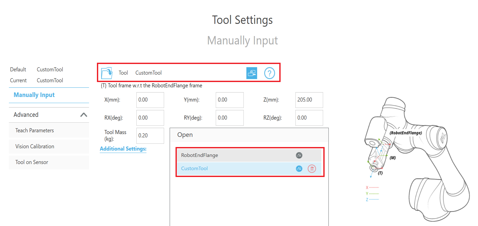
Use of ChangeTCP TMScript command is recommended whenever it is necessary to force use of the proper tool frame. For example for scan and calibration requests, we always need “0 RobotEndFlange” but when picking based on the result of Get Object Pose, “1 Custom Tool” needs to be selected.
1.5 Connecting to robot from TMFlow
To proceed with the following configuration of the Photoneo-Techman interface, a remote connection from a PC to the robot controller using TMFlow SW is recommended. Leveraging the secondary Ethernet port configured in section 1.3, you can now initiate a session using the TMFlow software.
Launch the TMFlow application on your PC and enter the simulation environment by selecting one of the robot models (e.g., TM12S). From simulation, you can then transition to a live connection with the physical robot hardware. The connection procedure is illustrated in the figure below.
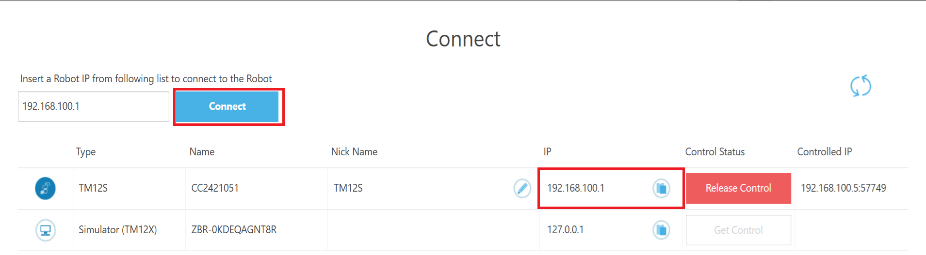
From the list of discovered devices, select the target robot by its IP address and click the “Connect” button. TMFlow will establish a live control session with the physical robot and you have full access to the system.
1.6 Switching from Auto to Manual Mode
Before implementing any program or configuration change, it is necessary to switch the robot from “Auto” to the “Manual” mode. This change is executed using a specific procedure on the Robot Stick controller. Follow the steps below:
Press and hold the M/A button until a beep sounds, and LED indicator starts flashing white
Press the sequence: + , - , + , + , -
Press M/A button again to switch to Manual mode, LED indicator should start flashing green
Press M/A button one more time to lock Manual - LED indicator should remain solid green
1.7 How to use Photoneo Main + Templates
Because the Techman robot controller is limited to single-script execution, the Photoneo interface was developed as a unified script that combines both the ‘user frontend’ and the ‘communication backend’. This file, named photoneo_main_ls.script, is the main script that must be copied to the robot as the first step of the installation.
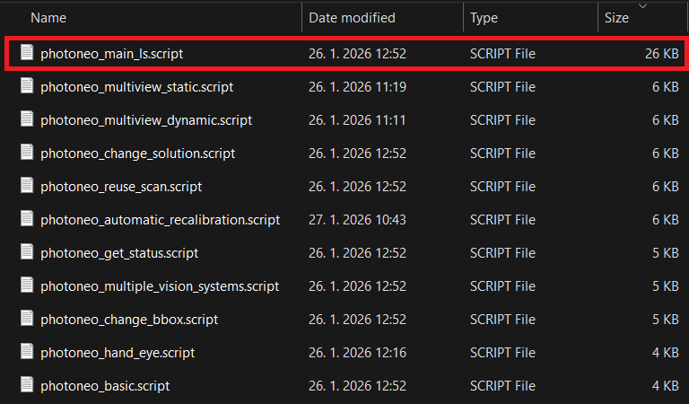
Open photoneo_main_ls.script in your favourite editor on the PC side. To copy this code to Techman robot, use TMFlow, Go to Project, start a new Project and select New Script, not New Flow:
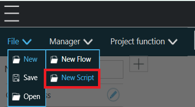
Now copy and paste the entire code from photoneo_main_ls.script to TMFlow script:
The photoneo_main_ls.script provides a basic example for a locator sequence. It demonstrates the essential workflow: connecting to Locator Studio, triggering a scan, requesting a object pose, and executing the subsequent pick-and-place operation.
Photoneo_main_ls.script was designed to be easily modified by replacing a MAIN PROGRAM section of the code with sections from different scripts provided in the module.
Example: How to Test the “Reuse Scan” Feature - In order to try this function, open the photoneo_reuse_scan.script file. Copy its entire MAIN PROGRAM block and paste it directly over the old MAIN PROGRAM block in your project.
Important
These templates are designed to work instantly, but you must make sure the feature you want to use is already set up and active in Locator Studio first. So for example if you want to test Change Bounding Box functionality, you need to have at least 2 bounding boxes configured in your solution.
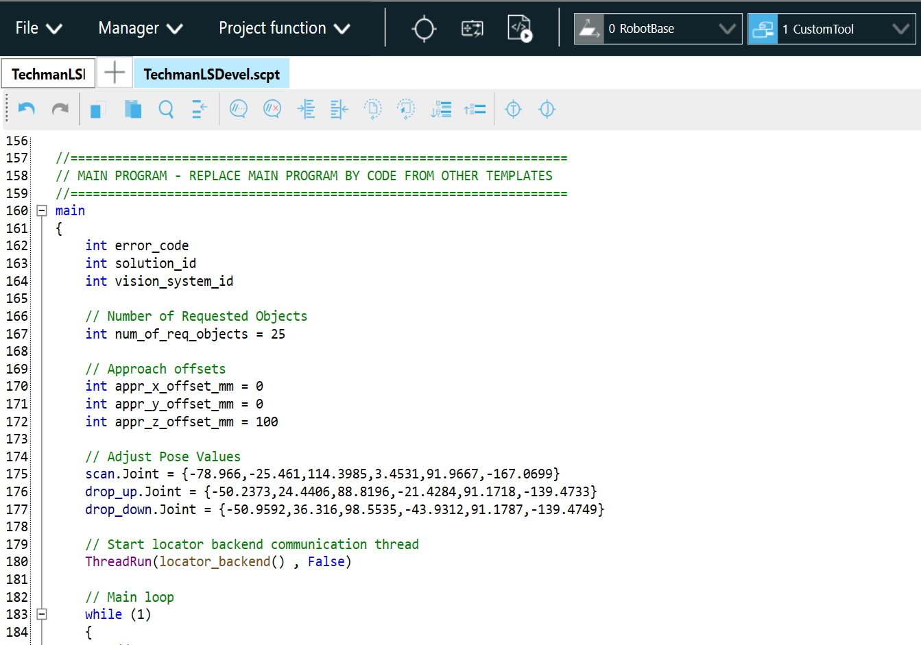
The MAIN_PROGRAM section of the code starts around line 150 and ends around 230. Feel free to modify according to your application requirements or replace an entire section of this code by code from other templates. It is always possible to revert back to the original state using code from template photoneo_basic.script.
2. Robot Module
Note
It is strongly recommended to read the Photoneo robotic API prior to this section. (user login: customer, password: Ready2LearnHow2Pick).
2.1 Connection to Photoneo Vision Controller
Note
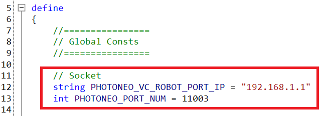
Establishment of connection to the Action Request Server running on the Vision Controller side happens at the beginning of the Communication Backend thread automatically. Two global constants are important in this step:
PHOTONEO_VC_ROBOT_PORT_IP - IP address of port on vision controller side
PHOTONEO_PORT_NUM - Port number used by Action Server (by default 11003)
Change PHOTONEO_VC_ROBOT_PORT_IP to match the IP address of the Vision Controller you’re connecting to, in case of this tutorial it is 192.168.1.1.
Requests can be sent to the Vision Controller only after a connection has been established. Successful connection is visualized by green Connected indicators on Deployment page after program on Techman side is started, see image below

2.2 Request List
This section describes available API calls provided by the Robot module. These procedures are intended for high-level control of the locator application.
Note
These procedures are defined in the communication backend and must not be edited!
Request |
Script definition |
Input |
Populates |
|---|---|---|---|
Calibration Start |
int calib_start(int solution_id, int vision_system_id) |
solution_id, vision_system_id |
g_error_code |
Calibration Add Point |
int calib_add() |
None |
g_error_code |
Calibration Save |
int calib_save() |
None |
g_error_code, g_calib_err, cal_pose_cart |
Calibration Stop |
int calib_stop() |
None |
g_error_code |
Scan Regular |
int scan_request(int vision_system_id, int hand_eye_mode) |
vision_system_id, hand_eye_mode |
g_error_code |
Scan Meshing |
int capture_request(int vision_system_id, int mesh_dynamic, int capture_gap) |
vision_system_id, mesh_dynamic, capture_gap |
g_error_code |
Reuse Scan |
int reuse_scan_request(int vision_system_id) |
vision_system_id |
g_error_code |
Get Poses |
int get_poses(int vision_system_id, int num_tar_req) |
vision_system_id, num_tar_req |
g_error_code, g_num_tar_rec, g_obj_dim_x, g_obj_dim_y, g_obj_rot_z, g_obj_nn_label, g_obj_max_z, g_obj_tilt |
Get Vision System Status |
int get_status(int vision_system_id) |
vision_system_id |
g_error_code, g_num_of_localized, g_num_of_planned, g_vs_status |
Change Solution |
int solution_change(int solution_id) |
solution_id |
g_error_code |
Start Solution |
int solution_start(int solution_id) |
solution_id |
g_error_code |
Stop Solution |
int solution_stop() |
None |
g_error_code |
Get Running Solution |
int get_running_sol() |
None |
g_error_code, g_running_sol |
Change Bounding Box |
int bbox_change(int vision_system_id, int bbox_id) |
vision_system_id, bbox_id |
g_error_code |
2.3 Example Programs
There are several template programs available in Photoneo Techman module that demonstrate how to properly use requests listed in section 2.2 for various use cases:
Techman Example |
Description |
|---|---|
|
This simple example demonstrates the basic workflow: It shows how to connect to a vision controller, send a scan request, request object poses, receive object poses, and execute picks.
The example also illustrates error handling as each function returns an error value assigned to |
|
The basic calibration example. Requirements: Initial calibration of the Vision System must be started and confirmed manually by the user on the Locator Studio side. Calibration Steps
Important: The calibration object—either a ball or marker pattern—must remain in its original position to ensure successful automatic recalibration. |
|
Same as photoneo_basic, but with switching between two Vision Systems.
The |
|
Same as photoneo_basic but with all solution-switching related requests.
It highlights how to activate different solutions using |
|
Same as photoneo_basic, but with multiple get_status request calls.
The |
|
Static Meshing example. This process shows stitching of multiple scans before initiating localization, which is particularly useful for complex scenes or large objects. It employs a static approach, where the robot pauses at each scanning position to trigger and capture scans. Procedure
|
|
Dynamic Meshing example. This setup leverages the LS integration of Photoneo Instant Meshing technology alongside the Parallel structured light technique provided by Motion Cam 3D. Note that Dynamic Meshing cannot be utilized with standard PhoXi 3D Scanners. Requirements
. Procedure
|
photoneo_reuse_scan |
Same as the photoneo_multiple_vision_systems example but introduces the LS feature
to reuse the scan data from VS1. This allows you to repeat the localization process with varied configurations without needing a new scan. |
3. Runtime
Once the solution is fully configured on the Vision Controller side, it is time to finalize the remaining steps on the robot side and proceed to executing the photoneo_main_ls.script
3.1 Teach Positions
After opening photoneo_main_ls.script or another template, there are a couple of local poses that need to be touched up before running the program. See TPoint declarations below:
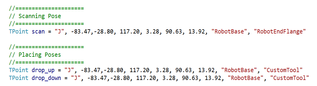
Besides 3 local poses scan, drop_up, drop_down it is also essential to define Approach point offsets defining a direction from which robot will approach target point

The easiest way to touch up poses in TMScript is probably to jog the robot to desired pose and hit Point/Target 🞋 button directly on robot flange. This will create a new TPoint variable at the end of the define section in your script and record the point - see image below. From there you can copy Joint or Cartesian values to main poses.

3.2 Gripper commands
There are no Gripper procedures located within photoneo_main_ls.script by default. This is left to the user to add to the existing code at appropriate places. An example of such a function is below:
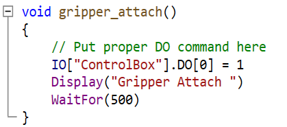
3.3 Runtime Prerequisites
Final pre deployment check before running Locator Studio interface from the robot side
Make sure that:
Locator Studio solution is properly configured on the Vision Controller side
Network Setup on Robot Side is completed and state server works
All Vision Systems defined in solution are calibrated
All local poses in main program have been touched up properly
Gripper procedures are prepared and working
3.4 Running photoneo_main_ls script
Deploy your solution. The Action Request Client (Robot) status on the Deployment page should be DISCONNECTED – from the Action Request Server, if the communication hasn’t been established yet.

Note
It is strongly recommended to decrease the override speed to 5% before running the program for the first time.
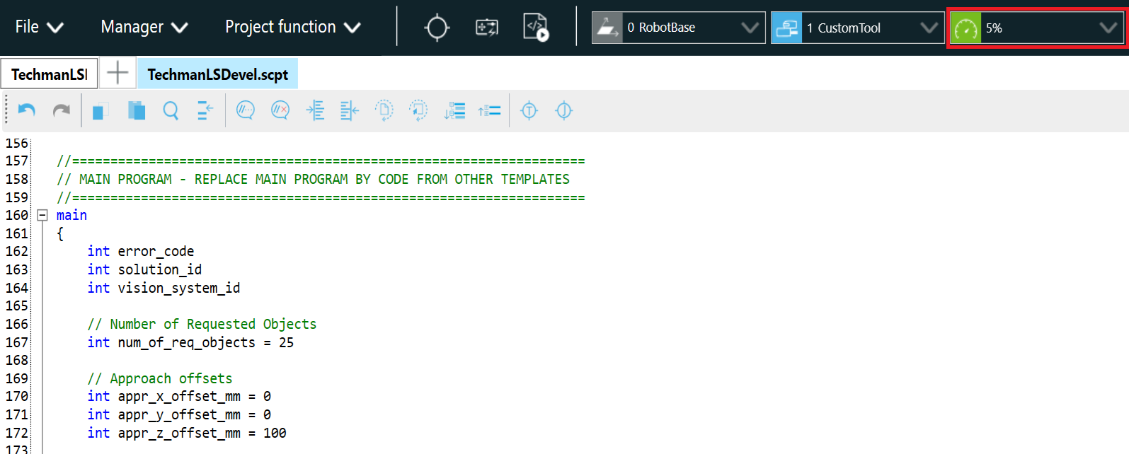
If connection has been established properly you will see Action Request Client and Robot State Server status turn to CONNECTED. At this point the sensor should capture the first scan and localization should start localizing objects.

If there is a pickable object in the scene and the Cartesian Pose for this object has been received by the robot controller, the robot should start moving towards the first object.
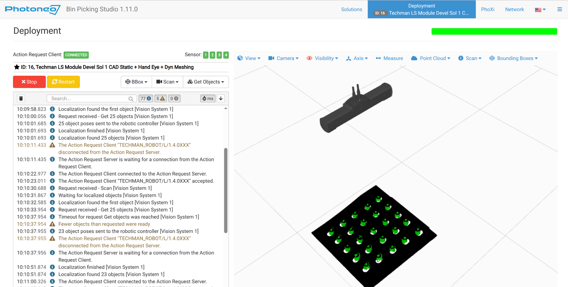
If everything looks fine, keep moving the robot towards the first target and check if the path is correct. At this point if the robot is too far from the object or pushes the object too deep, then make modifications to object origin or tool TCP setup
If robot movement looks fine, set up your own placing routine and slowly ramp up speed back to 100%
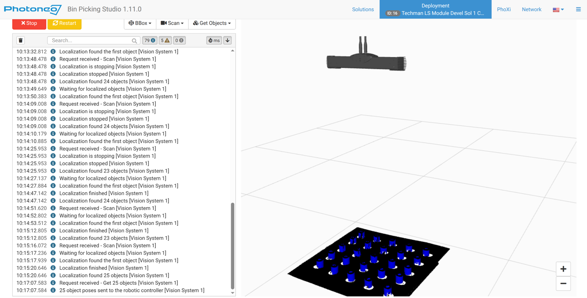
Congratulations, you have successfully deployed Photoneo Techman Interface. You can now focus on improving your application further. Use CheatSheet and Program Templates as your guidelines.