Calibration
Calibration is an essential part of a configuration. Although poor calibration may not be the sole cause of inaccuracies, it may surely be the source of the largest errors. Good calibration is the key to precise position reporting, picking, and, in the end, the correct placement of the localized object.
This tutorial will take you step-by-step from the preparation of your solution for calibration, describing best practices along the way, to the final verification of the correctness of your calibration.
Contents
1 Calibration?
1.1 What is calibration
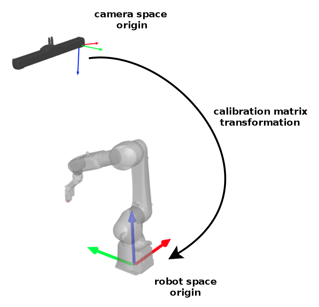
The point cloud from a 3D sensor has its origin in the camera unit of the device. This means that when objects in the scene are localized, localization returns their position and rotation coordinates in camera space. On the other hand, the robot (usually) has its origin in its own base - robot space - regardless of the position of the camera.
1.2 Types of calibration
As already mentioned, the target space does not have to be the robot’s base frame. The robot can work in a custom user frame. In both of these cases we perform the robot-camera calibration, in the Studio we recognice two its basic types:
Robot space, external fixed sensor position (Extrinsic calibration)
Robot space, sensor mounted on the robotic flange (Hand-eye calibration)
There are also two other calibration types that are not connected to the robot directly.
Marker space, single sensor position
only available in the locator solution types
this is a marker-camera calibration
Multi-sensor calibration
for Static MultiView approach available for CAD localization engine
this is a camera-camera calibration
1.2.1 Robot space, external fixed sensor position (Extrinsic calibration)
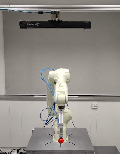
This calibration type is used in setups where the 3D sensor is mounted in a stationary position in the robotic cell, usually above the bin. It is only required that the 3D sensor be stationary relative to the robot’s base; the 3D sensor does not need to be stationary relative to the robotic cell itself. Any change in the relative position between the 3D sensor and the robot after the calibration will render the calibration matrix invalid and the whole calibration procedure must be repeated. In other words, the 3D sensor must not be moved in relation to the robot after the system has been calibrated.
Since the 3D sensor is fixed, the calibration matrix defines the transformation directly to the robot base coordinate system.
1.2.2 Robot space, sensor mounted on the robotic flange (Hand-eye calibration)
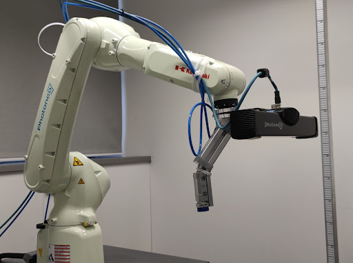
This calibration type is used in setups where the 3D sensor is mounted on the robotic arm itself. For the hand-eye calibration to work correctly, the 3D sensor must be mounted behind the very last joint (e.g. on the robotic flange or the gripper). Any change done to the sensor’s mount position after the calibration renders the calibration matrix invalid and the whole calibration procedure must be carried out again.
Since the 3D sensor is not fixed, the calibration matrix defines the transformation to the robot’s TCP which needs to be known in the moment of object localization. Using the TCP data the pose of the object can be transformed to the robot base coordinate system.
1.2.3 Marker space, single sensor position
This calibration type uses a marker pattern for definiton of a common coordinate space between the camera and the robot. The 3D sensor is usually mounted statically but can be also mounted directly on the robotic arm in which case the scan acquisition must be executed from the same single robot pose.
The calibration is performed in two steps:
Vision system is calibrated to marker space using a single calibration point
Custom coordinate space is defined on the robotic controller with its origin in the marker pattern origin
Any change done to the sensor’s mount position or the robot position after the calibration renders the calibration matrix invalid. If the marker pattern did not move (is in a fixed position) only the relevant step of the calibration must be repeated (e.g. vision system calibration if the sensor was moved).
1.2.4 Multi-sensor calibration
The calibration is performed in these steps:
Primary sensor is calibrated first
All secondary sensors are calibrated with respect to the Primary sensor
1.3 Calibration sharing
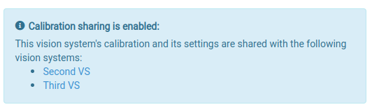
When this parameter is enabled, all vision system using the same 3D sensor and calibration configuration will have any calibration-related parameter updated together:
calibration matrix
calibration profiles
settings of automatic calibration
3 Requirements and setup
Before the calibration can be performed, it is necessary to configure the network parameters, calibration-related parts of the solution, robot controller and prepare the calibration tool.
2.1 Network
2.2 Vision System
The vision system that is to be calibrated needs to be fully configured. Before the calibration is started, make sure that the following parameters of the vision system as configured correctly:
Sensor ID - 3D sensor used with this vision system. If the sensor interface is configured correctly, the connected 3D sensors will be in the drop-down list of available 3D sensors
Sensor model - determined automatically based on the chosen 3D sensor
Calibration space and sensor position - specifies the calibration space and the mount position of the 3D sensor
During the calibration procedure, preconfigured default scanning profile for calibration is used. In order to use a customized scanning profile, please enable the setting Use custom scanning profile for calibration.
2.3 Robot
Base frame offset
Bin Picking Studio
Locator Studio
Tool center point
The TCP pose is one of the inputs into the calibration matrix computation.
Bin Picking Studio
Based on the calibration type the following requirements must be met:
Robot space, external fixed sensor position (Extrinsic calibration) During calibration, the selected tool (tool0 or custom) is not relevant but cannot be changed during the whole calibration procedure. During localization, the selected tool is not relevant.
Robot space, sensor mounted on the robotic flange (Hand-eye calibration) During calibration, the tool0 must be selected and cannot be changed during the whole calibration procedure. During localization, the selected tool is not relevant, however, the Robot State Server must be running. When using Robot State Server as Robot state input it is possible to tell whether the reported TCP pose is correct during the calibration procedure - the tool0 is selected and the base frame offset is configured, if necessary. If the system detects a large difference between expected and reported TCP pose, a warning is displayed. Moreover, it is possible to display the frame of the expected TCP and the reported one using the Axis widget of the 3D visualizer:
Tool 0 (robot model) - the expected TCP
Tool Pose (robot controller) - the reported TCP
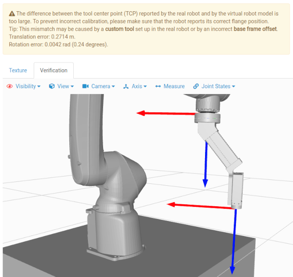 Image 5 - Mismatch of the coordinate frames of the expected and reported TCP
Locator Studio
A tool must be selected (tool0 or custom) and cannot be changed during the whole calibration procedure.
Based on the calibration type the following requirements must be met:
Robot space, external fixed sensor position (Extrinsic calibration) During calibration, the selected tool (tool0 or custom) is not relevant but cannot be changed during the whole calibration procedure. During localization, the selected tool is not relevant.
Robot space, sensor mounted on the robotic flange (Hand-eye calibration) During calibration, the selected tool (tool0 or custom) is not relevant but cannot be changed during the whole calibration procedure. During localization, the same tool must be selected as during the calibration procedure when retrieving the current TCP that is to be included in the Scan request.
Robot State Server
Bin Picking Studio
The Robot State Server constantly provides the Vision controller with the current state of the robot. For the calibration procedure, it is the TCP pose.
Procedure providing the Robot State Server functionality is a part of each Robot module. Please follow the integration guide for your robotic brand to configure the Robot State Server correctly.
Locator Studio
2.4 Calibration tool
Based on the calibration type a different calibration tool is used. These tools are delivered in the BPS / LS package.
Robot space, external fixed sensor position (Extrinsic calibration) The calibration tool used is a calibration ball. Instead of the calibration ball delivered by Photoneo, it is also possible to use a custom ball with suitable properties - the ball must be perfectly round and made of a material (surface) appropriate for scanning (smooth and not highly reflective). The ball must be mounted onto the robot’s endpoint (either the flange or the gripper). Make sure the ball does not move during the calibration procedure and that the majority of the ball surface is clearly visible.
Robot space, sensor mounted on the robotic flange (Hand-eye calibration), Marker space, single sensor position and Multi-sensor calibration The calibration tool used is a marker pattern. Place the pattern within the reach of the robot so that the calibration pattern is visible to the 3D sensor. Make sure the pattern does not move during the calibration procedure and that it is perfectly flat (when using a custom printed pattern).
3 Simulated, Manual, Semi-automatic and Automatic calibration
Note: Marker space calibration and Multi-sensor calibration are always performed manually and the Robot state input is nor required.
Simulated calibration
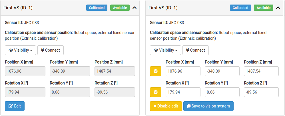
Manual calibration
Semi-automatic calibration
The Robot module contains a program template for adding of the calibration points by calling the Add calibration point request. It is necessary to teach/update the robot calibration poses before running the program.
Bin Picking Studio The robot state is automatically obtained from the Robot State Server which must be running.
Note: Manual and Semi-automatic calibration are also reffered to as calibration performed and verified by operator.
The template for semi-automatic calibration contains the requests for starting, saving and stopping the calibration procedure, but they are commented out. Uncomment them after enabling the automatic calibration inside the vision system calibration settings.
4 Robot-camera & Marker-camera calibration procedure
To start the manual or semi-automatic calibration navigate to the Calibration page inside the solution. It shows the list of all defined Vision systems with the following information:
ID - ID of the Vision system
Name - name of the Vision system
Sensor ID - ID of the 3D sensor used by the Vision system
Sensor status - current status of the 3D sensor used by the Vision system
Sensor model - model of the 3D sensor used by the Vision system
Calibration space and sensor position - calibration type based on chosen 3D sensor mount position
Calibrated - whether the vision system is already calibrated
Calibration accuracy [mm] - accuracy of any previous calibration (if available)

Calibration can only be successfully started if the 3D sensor used by the Vision system is available. Use the Reload sensors button to update the statuses of 3D sensors.
Please verify the configuration one more time and then click the button Start calibration for the Vision system you wish to calibrate.
4.1 Confirming parameters of Manual and Semi-automatic calibration
Before the manual and semi-automatic calibration is started its parameters must be confirmed.
Calibration ball selection
Note: Only available for Robot space, external fixed sensor position (Extrinsic calibration)
Robot state input
Bin Picking Studio
Selection of the Robot state input is only relevant when performing manual calibration. The current state of the robot (the TCP pose) can be provided in two ways:
Robot State Server Use this option to read the current robot state automatically from the robot controller.
Operator Use this option when the Robot State Server is not available for some reason. The current robot state is provided by the operator manually. When adding of a new calibration point is requested, a form appears that needs to be filled with the current TCP data from the teach pendant. The brand of the robot that needs to be chosen specifies the rotation formalism used in the TCP pose. Note: This feature is only available for selected robotic brands. For other robotic brands, it can be used only in case the rotation formalism of the used brand is the same as that of one of the supported robotic brands or, when converting the rotation formalism of used robotic brand to the rotation formalism of one of the supported robotic brands.
Locator Studio
The Robot State Server functionality is not available in the Locator Studio.
When performing manual calibration, the current state of the robot (the TCP pose) is provided by the operator manually. When adding of a new calibration point is requested, a form appears that needs to be filled with the current TCP data from the teach pendant.
4.2 Confirming parameters of Automatic calibration
To enable the automatic calibration navigate to the Vision system -> Calibration.
In order to be able to turn on this feature folloving requirements must be met:
Calibration by the operator must be performed first
this calibration, either manual or semi-automatic, is verified by the operator
Calibration point dataset must contain at least 9 calibration points
Accuracy of the calibration performed by the operator cannot exceed the maximal value of the Minimal allowed accuracy for the Automatic calibration
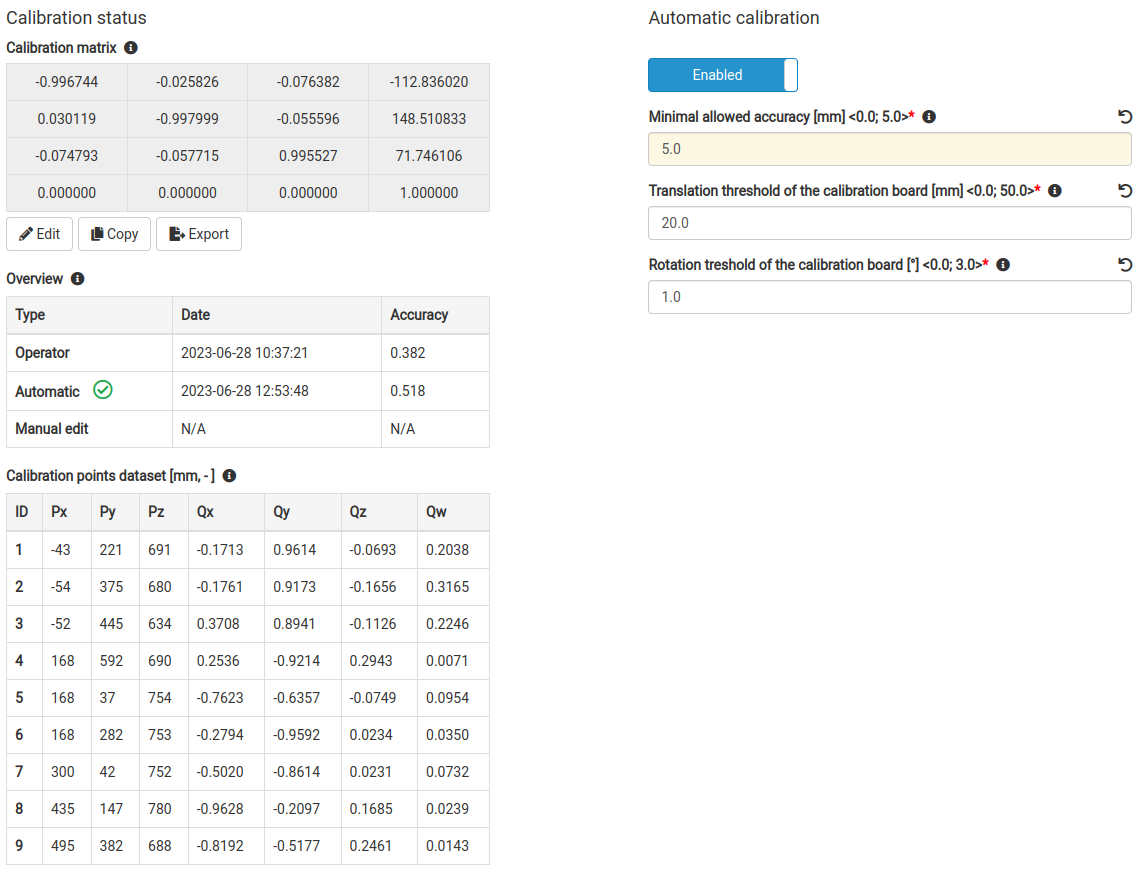
Calibration point dataset contains robot calibration poses from the last calibration performed by the operator. The same robot calibration poses must be used during the automatic calibration.
After enabling the automatic calibration, the user has option to define parameters:
Minimal allowed accuracy - minimal allowed calibration accuracy of the automatic calibration result. If exceeded, the result won’t be saved.
Rotation and translation thresholds for the calibration tools - the calibration tool (ball/marker pattern) must be statically mounted (ball on the gripper, pattern in the robotic cell) and cannot move more than these thresholds between the calibration performed by the operator and the automatic calibration
Calibration ball type (and radius) - automatically chosen radius of the calibration ball based on the ball selected during calibration performed by the operator
4.3 Calibration
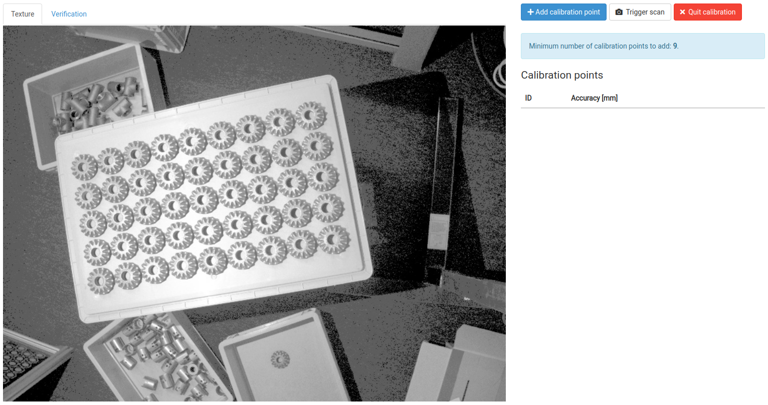
The calibration interface consists of the following parts:
visualization - Texture tab and Verification tab which can be switched between:
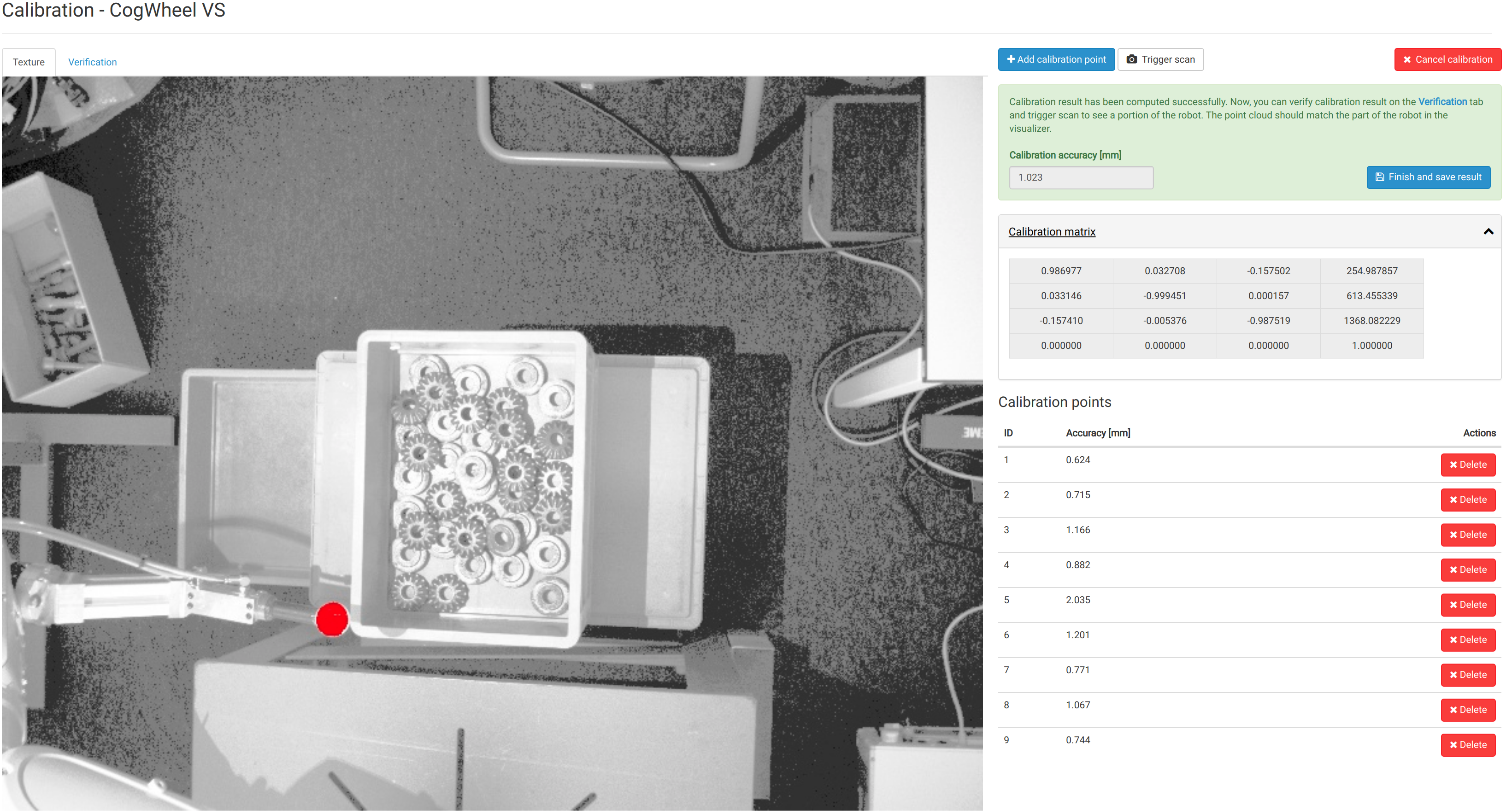
Texture image (Texture tab) The texture image is from the last scan acquisition. For the extrinsic calibration, the localized calibration ball is highlighted with green color if it was found successfully. On the other hand, if not enough surface of the ball is visible or another object of a similar shape was detected, that piece of texture will be highlighted with red color.
3D visualizer (Verification tab)
Bin Picking Studio The visualizer displays the robot with the gripper, collision objects, 3D sensor of the vision system currently being calibrated, and the point cloud.
Locator Studio The visualizer displays 3D sensor of the vision system currently being calibrated, and the point cloud.
Add calibration point - button for manual adding of a calibration point
Note: For Marker space calibration there is Calibrate button instead - the calibration is done by a single scan
Trigger scan - button for triggering a new scan, usually used to acquire the current point cloud for verification purposes
List of calibration points - list of all successfully added calibration points with individual accuracies and the option to delete a point
Note: Not available for the Marker space calibration
after the required number of calibration points has been added, the following items appear:
Calibration matrix - the result of the calibration procedure
Calibration accuracy - overall accuracy of the calibration
Note: Not available for the Marker space calibration
Save calibration result - button for saving the result (calibration matrix) into the vision system
Note: Calibration interface for the automatic calibration does not enable adding of a calibration point, triggering of a scan or saving of the calibration result.
Robot calibration poses
During the extrinsic calibration, the 3D sensor needs to capture the calibration ball in various places of the whole bin volume. Similarly, during the hand-eye calibration, the 3D sensor needs to capture the marker plate from various viewpoints. Therefore, move the robot to various poses, with joint orientations as diverse as possible, and in every one of them, add a new calibration point.
During the Marker space calibration, without moving the marker pattern, a custom coordinate frame is defined on the robotic controller with its origin in the origin of the marker pattern (beware of the direction of the axes).
Adding a calibration point
A new calibration point is added either:
by the operator manually, by pressing the Add calibration point button in the calibration web interface
by the robot by calling the Add calibration point request
When a new calibration point is added, a scan acquisition is triggered and the calibration tool (ball/pattern) is detected. If the detection is successful, a flash message appears notifying the user about the successful result. In case the calibration point failed to be added, a persistent error message will provide information about the cause and how to solve the error.
The required number of calibration points is 9 for both the extrinsic and hand-eye calibration. Only after the required number of calibration points has been added does the resulting calibration matrix and information about the calibration accuracy become available.
3D sensor and point cloud position
After the 4th point is added during the extrinsic calibration and the 6th during the hand-eye calibration, the model of the 3D sensor of the currently calibrated vision system starts to reflect the pose of the real 3D sensor. At the same time, the point cloud is displayed.
4.4 Verification
Note: Accuracy info is not avaiable for the Marker space calibration.
Each successfully added calibration point has an ID and its own accuracy score expressed in millimeters. The lower the accuracy score, the higher the confidence in the accuracy. When a point’s accuracy score is too high, such point can be removed from the dataset using the Delete button.
Calibration quality is expressed by the aggregate score of Calibration accuracyexpressed in millimeters. Always aim for a score as low as possible. However, the value is affected by many factors, such as the size of the 3D sensor, the quality of the calibration ball, scanning parameters and the lighting conditions, and the size of the robotic arm. Even an accuracy value of several millimeters can be considered satisfactory.
Bin Picking Studio
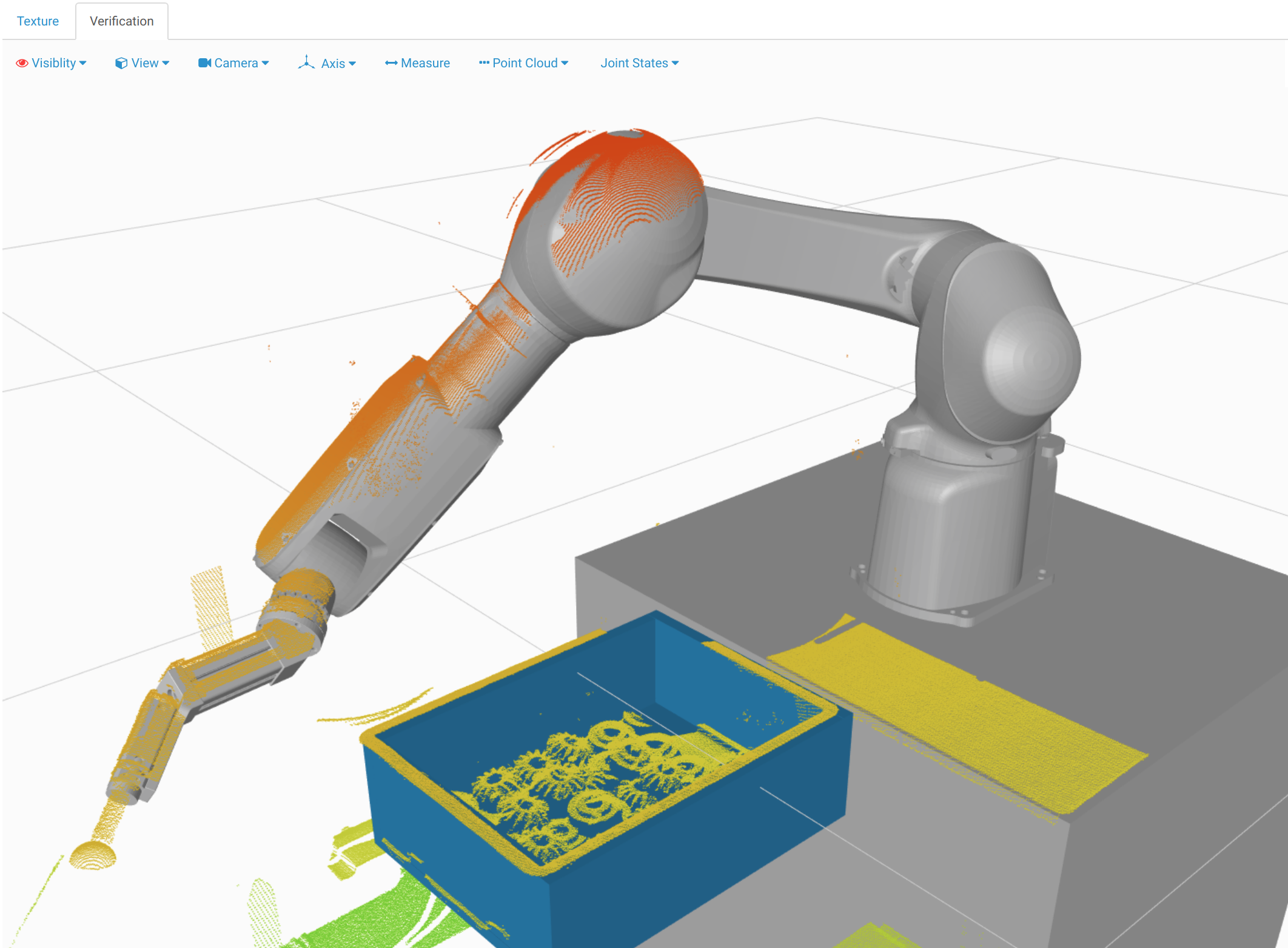
Bin Picking Studio 3D visualizers contain the accurate 3D model of the robot. A more comprehensive way of verifying the calibration accuracy is to visually inspect the overlap of the point cloud and the 3D model of the robot. This, however, requires functional Robot State Server in order to have the 3D model of the robot in the actual position.
Locator Studio
Calibration quality is verified through the value of Calibration accuracy.
Besides that, the approximately correct result (without taking accuracy into consideration) can be confirmed by evaluating the position of the 3D sensor and the point cloud in the scene.
For the extrinsic and hand-eye calibration, the origin of the scene lies in the origin of the coordinate frame of the robotic controller with respect to which the calibration was carried out. Usually that means the origin of the robot base. The relative position of the model of the 3D sensor and the scene origin should then be similar (the same) as the relative position of the real 3D sensor and the robot base in reality.
For the Marker space calibration, please verify the origin of the scene lies in the origin of the marker pattern.
5 Multi-sensor calibration procedure

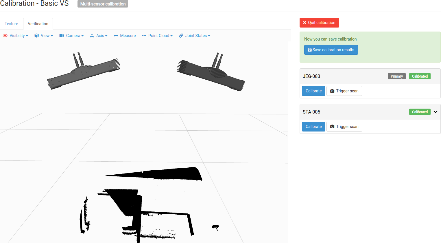
The calibration interface consists of the following parts:
visualization - Texture tab and Verification tab which can be switched between:
Texture image (Texture tab) The texture image is from the last successful scan acquisition.
3D visualizer (Verification tab)
Bin Picking Studio The visualizer displays the robot with the gripper, collision objects, 3D sensors of the vision system currently being calibrated, and the point cloud.
Locator Studio The visualizer displays 3D sensors of the vision system currently being calibrated, and the point cloud.
Calibration controls for each sensor:
Calibrate- button for calibrating a sensor
Trigger scan - button for triggering a new scan, usually used to acquire the current point cloud for verification purposes
Calibration matrix - the result of the calibration procedure
not available for the primary sensor (always identity)
after all sensors have been successfully calibrated the button for saving the result into a vision system appears - Save calibration result
Calibrating a sensor
Calibration result
6 Tips and Troubleshooting
Although calibration looks like a simple task, there are some best practices for reaching the highest possible accuracy:
Maneuver the robot to positions as diverse as possible. Try to add poses with great joint differences.
During extrinsic calibration, place the ball to various places of the bin (such as its corners), including its approximate center. Cover the entire bin volume with calibration points if possible.
During hand-eye calibration, scan the marker pattern from various robot poses.
Avoid using small balls for extrinsic calibration. A bigger ball means a greater scanned surface and more points of the point cloud dedicated to ball recognition. This is especially important when using larger models of 3D sensors.
If you encounter any of these errors:
The whole point cloud is offset in the world’s Z-axis. It does not match the virtual model.
Some robotic brands require a custom user frame to be set on the robotic controller. Refer to section 2.3 for more information.
I can see the calibration ball on the texture image but the ball is not recognized. Previous points have been added successfully.
The camera can sometimes see parts of the scene that cannot be scanned. Make sure the calibration ball is also visible in the point cloud (check in the PhoXi Control). The ball may be too close to the 3D sensor and thus outside of the scanning volume.