Integration Guide FANUC LS
Note: It is strongly recommended to read the Robot communication overview prior to this integration guide.
Note 2: It is strongly recommended to use the latest version of the integration guide included in the latest available version of the robot module. To download the robot module, please visit the official Photoneo website.
Contents
1 Prerequisites
Prior to the setup, please ensure that your robot controller meets the following criteria:
System version:
To check the system version go to Menu -> Next -> Status -> Version ID
v8.10 and higher
v6.40 - v7.70 supported with certain limitations
Option R648 User Socket Msg available (Socket Communication)
To verify the option is installed on your robot controller go to Menu -> Next -> Status -> Version ID -> Next -> F3[ORDER FI]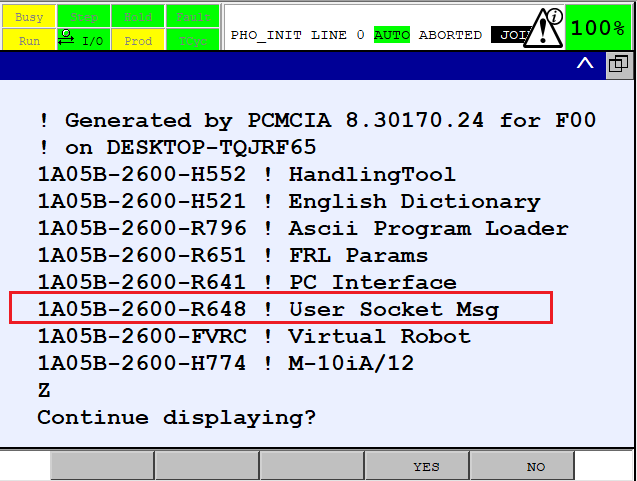
2 Robot controller setup
2.1 Controller configuration
2.1.1 Setting the IP addresses of the Ethernet ports
The first step of the process is to configure the IP addresses of the robot controller.
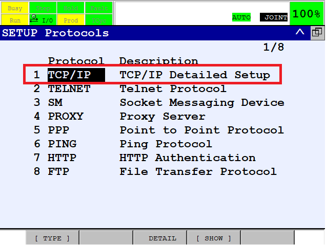
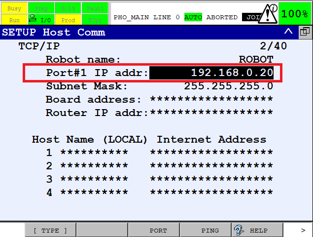
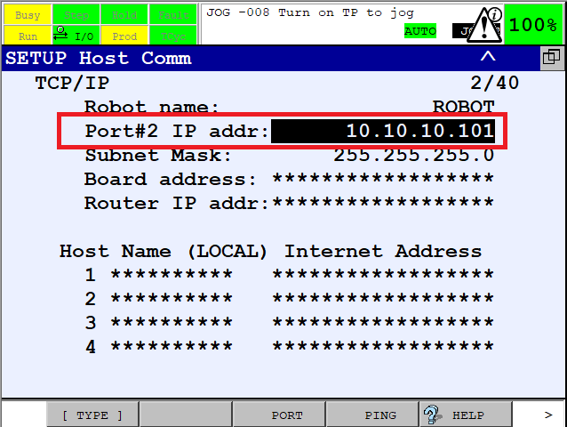
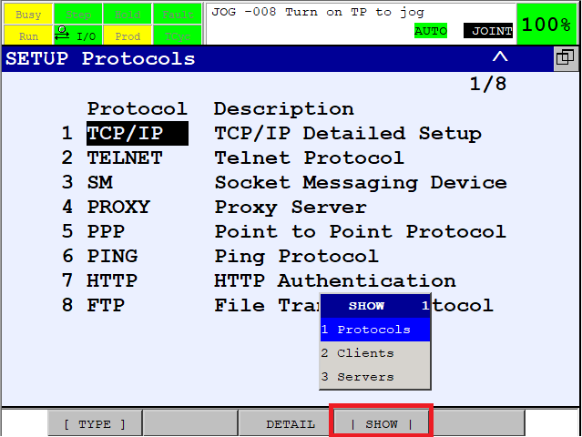
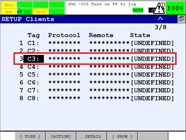
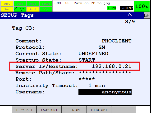
2.1.2 Configuring the TCP/IP client
The main Photoneo Locator application works in client mode. Configure the TCP/IP Client for this purpose.
2.2 Robot module installation
2.2.1 Loading the Robot module files
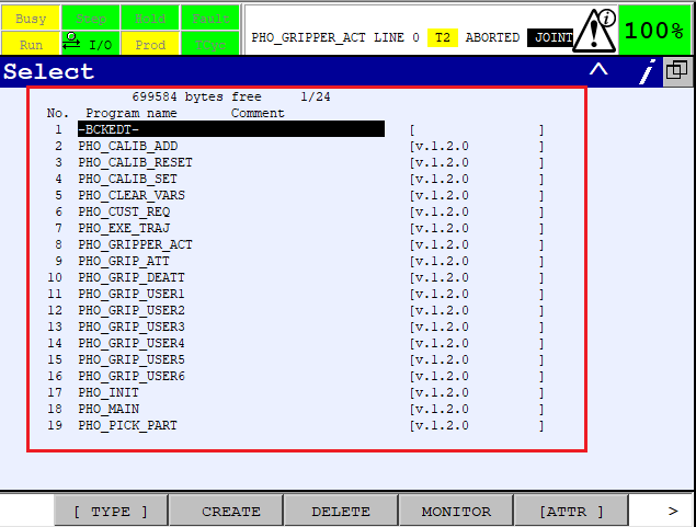
The Robot module consists of a Karel binary and multiple TP programs which need to be copied to the robot controller.
Extract the Robot module archive (.zip file). Besides the documentation PDF and binaries for various versions of Karel, the archive contains folders with TP and LS versions of programs.
The core programs are located in folder:
PhotoneoLocator
Besides that Photoneo provides an example locator program and a semi-automatic calibration example program located in folder ExamplePrograms:
PHO_MAIN_LOC_BASIC
PHO_CALIBRATION
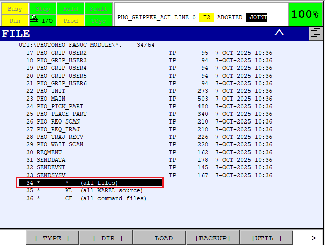
Copy the core files (and optionally the example program you wish to use) to a USB stick and plug it into the Teach Pendant. We recommend putting all the programs into a single folder located at the root of the USB stick (on the screens below the folder name is PHOTONEO_FANUC_MODULE).
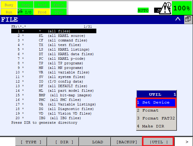
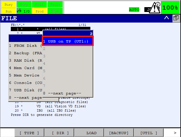
*.*(all files) to show all items on the USB.
3 Robot module
The Robot module is designed to be easily integrated into existing applications written as TP programs. The Karel binaries run as background tasks with which the TP programs of the Robot module interact.
3.1 Robotic API
Note: It is strongly recommended to read the Photoneo robotic API prior to this section.
This section describes available API calls provided by the Robot module. These procedures are intended for high-level control of the locator application.
3.1.1 Connection procedures
Command |
Description / Usage |
|---|---|
Connect to Action Request Server
RUN LOC_CLIENT |
Description
Starts background Karel task which establishes a new connection to the Action Request Server.
Usage
The procedure should be called only once at the beginning of the program.
|
Wait for connection to Action Request Server
WAIT (F[1]=ON) |
Description
Blocks the execution of the program until a valid connection to the Action Request Server is established (flag
F[1: CONNECTED] is set).Usage
This command is usually executed right after the command
RUN LOC_CLIENT. |
3.1.2 Communication procedures
Note: Please read Action requests for detailed documentation of these procedures.
Locator requests
Request |
Input registers |
Output registers |
|---|---|---|
Scan request
PHO_REQ_SCAN |
R[2: PHO VISION ID] - vision system IDR[10: HAND_E_ENBLE] - enable/disable hand-eye scanning (set to 1 to enable, otherwise disabled)If
R[10: HAND_E_ENBLE] is enabled, the current TCP is sent. The UFRAME and UTOOL used are then specified by:R[11: HAND_E_UFRME] - UFRAME IDR[12: HAND_E_UTOOL] - UTOOL ID |
R[4: PHO ERROR DATA] - result of request sending operationNote: The response is received by the procedure Wait for scan completion.
|
Get objects request
PHO_REQ_GET_POSES |
R[2: PHO VISION ID] - vision system IDR[5: NUM_TAR_REQ] - number of requested object poses (value == 0 for all available, max value == 99) |
R[4: PHO ERROR DATA] - result of request sending operationPR[1] - PR[99] - received object poses as XYZPRW pose variablesR[6: NUM_TAR_REC] - number of received object poses |
Calibration requests
Request |
Input registers |
Output registers |
|---|---|---|
Add calibration point request
PHO_CALIB_ADD |
The current TCP is sent. The UFRAME and UTOOL used are specified by:
R[13: CAL_UFRME] - UFRAME IDR[14: CAL_UTOOL] - UTOOL ID |
|
Solution requests
Request |
Input registers |
Output registers |
|---|---|---|
Change solution request
PHO_CHANGE_SOL |
|
|
Start solution request
PHO_REQ_START_SOL |
|
|
Stop solution request
PHO_REQ_STOP_SOL |
— |
|
Get running solution request
PHO_REQ_RUN_SOL |
— |
R[4: PHO ERROR DATA] - error codeR[3: PHO SOLUTION ID] - solution ID |
Response receiving procedures
Request |
Input registers |
Output registers |
|---|---|---|
Wait for scan completion
PHO_WAIT_SCAN |
— |
|
3.1.3 List of used registers
Flags
The Robot module utilizes flags F[1] - F[3]. These flags cannot be used for other purposes. From these utilized flags the following ones are relevant for the user:
Flag |
Read / Write access |
Description |
|---|---|---|
|
read-only |
The current state of the connection to the vision controller.
See Connection procedures for more information.
|
Registers
The Robot module utilizes registers R[1] - R[14]. These registers cannot be used for other purposes. From these utilized registers the following ones are relevant for the user:
Register |
Read / Write access |
Description |
|---|---|---|
|
read and write |
Vision system ID used in requests that take it as a parameter. |
|
read and write |
Solution ID used in Change solution request, Start solution request, and Get running solution request. |
|
read-only |
|
|
read and write |
The number of requested object poses, input of the Get objects request. |
|
read |
The number of received object poses, output of the Get objects request. |
|
read and write |
Register reserved for executing movements from the TP side - looping over received object poses. See the Main program example for usage. |
|
read and write |
Enables/disables hand-eye scanning, input of the Scan request. |
|
read and write |
Specifies UFRAME ID of the current TCP sent in the hand-eye Scan request. |
|
read and write |
Specifies UTOOL ID of the current TCP sent in the hand-eye Scan request. |
|
read and write |
Specifies UFRAME ID of the current TCP sent in the Add calibration point request. |
|
read and write |
Specifies UTOOL ID of the current TCP sent in the Add calibration point request. |
To open the DATA Registers screen press Data. As shown in the figure below, comments were automatically added to the registers utilized by the robot module.
Note: In order to switch between register types (standard, position, etc.) press F1[TYPE] and select the desired type.
Position registers
The Robot module utilizes position registers PR[1] - PR[99]. These position registers cannot be used for other purposes.
Register |
Read / Write access |
Description |
|---|---|---|
|
read |
Position registers used for storing object poses returned by the Get objects request. |
To open the DATA Registers screen press Data. As shown in the figure below, comments were automatically added to the registers utilized by the robot module.
Note: In order to switch between register types (standard, position, etc.) press F1[TYPE] and select the desired type.
3.2 Example programs
The following section contains the Main program example and the calibration template which show the correct usage of the robotic API.
The Main program example also contains basic error handling.
3.2.1 Main program example
moves to a scanning pose where it requests the first scan
then it requests object poses
if no error occurred, it picks all reported objects in a loop:
the robot goes to a predefined start pose from which it moves to an approach pose above the object
then it moves in a linear path towards the object and picks it (gripper command needs to be implemented here)
after picking, it moves in a linear path to a deapproach pose above the object and then outside the scanning volume
finally, the placing procedure is executed (needs to be implemented)
when all objects are picked, next scan is requested
Name: PHO_MAIN_LOC_BASIC (located in folder ExamplePrograms)
 1:  !INITIALIZATION ;
 2:  CALL PHO_CLEAR_VARS    ;
 3:  !Set UTOOL and UFRAME ;
 4:  UTOOL_NUM=1 ;
 5:  UFRAME_NUM=1 ;
 6:  !Set Number of Requested Targets ;
 7:  R[5:PHO NUM_TAR_REQ]=3    ;
 8:  !Start Loc Client ;
 9:  RUN LOC_CLIENT ;
10:  !Move To Scanning Position ;
11:J P[1] 100% CNT100    ;
12:  !Wait For Establishing Connection ;
13:  WAIT (F[1:CONNECTED]=ON)    ;
14:   ;
15:  !============================= ;
16:  !MAIN LOOP ;
17:  !============================= ;
18:  !SCAN REQUEST ;
19:  LBL[1] ;
20:  !Vision System 1 ;
21:  R[2:PHO VISION_ID]=1    ;
22:  !Send Scan Request ;
23:  CALL PHO_REQ_SCAN    ;
24:  !Wait For Scan ;
25:  CALL PHO_WAIT_SCAN    ;
26:  !If OK then Continue to Get Poses ;
27:  IF R[4:PHO ERROR_DATA]=0,JMP LBL[2] ;
28:  !If No Object Found, Rescan ;
29:  IF R[4:PHO ERROR_DATA]=5,JMP LBL[1] ;
30:  !If Comm or Other Error Abort ;
31:  ABORT ;
32:   ;
33:  !GET POSES REQUEST ;
34:  LBL[2] ;
35:  !Send Get Poses Request ;
36:  CALL PHO_REQ_GET_POSES    ;
37:  !If OK, then proceed to picking ;
38:  IF R[4:PHO ERROR_DATA]=0,JMP LBL[3] ;
39:  !If Empty Scene, Rescan  ;
40:  IF R[4:PHO ERROR_DATA]=501,JMP LBL[1] ;
41:  !If No Object Found yet, Rescan ;
42:  IF R[4:PHO ERROR_DATA]=502,JMP LBL[2] ;
43:  !If No Object Found Then Rescan ;
44:  IF R[4:PHO ERROR_DATA]=503,JMP LBL[1] ;
45:  !If objects rejected yet, Rescan ;
46:  IF R[4:PHO ERROR_DATA]=504,JMP LBL[2] ;
47:  !If all object rejected, Rescan ;
48:  IF R[4:PHO ERROR_DATA]=505,JMP LBL[1] ;
49:  !If Comm or Other Error, Abort ;
50:  ABORT ;
51:   ;
52:  !MANIPULATION ;
53:  LBL[3] ;
54:  !Loop Setup ;
55:  FOR R[8:PHO LOOP ITER]=1 TO R[6:PHO NUM TAR RCV] ;
56:  !Move to Start Position ;
57:J P[2] 100% CNT100    ;
58:  !Approach Pose ;
59:J PR[R[8]] 25% CNT100 Offset,PR[100:PHO APR OFFSET]    ;
60:  !Grasp Pose ;
61:L PR[R[8]] 1000mm/sec FINE    ;
62:  !Insert your Gripper Command ;
63:  !CALL MY_GRIPPER_CMD ;
64:  !Deaproach Pose ;
65:L PR[R[8]] 1000mm/sec CNT100 Offset,PR[100:PHO APR OFFSET]    ;
66:  !Move Out Of Scanning Vol ;
67:J P[3] 100% FINE    ;
68:  !Placing ;
69:L P[4] 1000mm/sec CNT100    ;
70:L P[5] 100mm/sec FINE    ;
71:  !Insert Your Gripper Command ;
72:  !CALL MY_GRIPPER_CMD ;
73:L P[6] 1000mm/sec CNT100    ;
74:  ENDFOR ;
75:   ;
76:  !Jump Back to Main Loop ;
77:  JMP LBL[1] ;
3.2.2 Calibration example
This program is a template for semi-automatic calibration.
Before running the program:
teach the calibration start pose
teach the individual calibration poses
start the calibration in the Locator Studio
Now you can start the program. It will move to individual calibration poses and send the Add calibration point request when it reaches them. Once all the calibration points are successfully added, the program ends. If you are satisfied with the calibration result, save it in the Locator Studio.
Name: PHO_CALIBRATION (located in folder ExamplePrograms)
 1:  !INITIALIZATION ;
 2:  !Clear Flags ;
 3:  CALL PHO_CLEAR_VARS    ;
 4:  !Set Calib Tool and Frame ;
 5:  R[13:PHO CALIB TOOL]=1    ;
 6:  R[14:PHO CALIB FRAM]=1    ;
 7:  !Start LOC_CLIENT ;
 8:  RUN LOC_CLIENT ;
 9:  WAIT (F[1:CONNECTED]=ON)    ;
10:   ;
11:  !Move to Calibration Start Pose ;
12:J P[...] 10% FINE    ;
13:   ;
14:  !Move to calibration pose 1 ;
15:J P[...] 10% FINE    ;
16:  CALL PHO_CALIB_ADD    ;
17:   ;
18:  !Move to calibration pose 2 ;
19:J P[...] 10% FINE    ;
20:  CALL PHO_CALIB_ADD    ;
21:   ;
22:  !Move to calibration pose 3 ;
23:J P[...] 10% FINE    ;
24:  CALL PHO_CALIB_ADD    ;
25:   ;
26:  !Move to calibration pose 4 ;
27:J P[...] 10% FINE    ;
28:  CALL PHO_CALIB_ADD    ;
29:   ;
30:  !Move to calibration pose 5 ;
31:J P[...] 10% FINE    ;
32:  CALL PHO_CALIB_ADD    ;
33:   ;
34:  !Move to calibration pose 6 ;
35:J P[...] 10% FINE    ;
36:  CALL PHO_CALIB_ADD    ;
37:   ;
38:  !Move to calibration pose 7 ;
39:J P[...] 10% FINE    ;
40:  CALL PHO_CALIB_ADD    ;
41:   ;
42:  !Move to calibration pose 8 ;
43:J P[...] 10% FINE    ;
44:  CALL PHO_CALIB_ADD    ;
45:   ;
46:  !Move to calibration pose 9 ;
47:J P[...] 10% FINE    ;
48:  CALL PHO_CALIB_ADD    ;
49:   ;
50:  !Move to Calibration Start Pose ;
51:J P[...] 10% FINE    ;
52:   ;
3.3 Error handling
If an error occurs during the execution of the operation requested by the sent request the error is stored in the register R[4: PHO ERROR DATA]. It is recommended to implement adequate error handling for your particular application after each synchronous request and response receiving procedure.
Error codes together with their description and troubleshooting can be found here.
Note: Error Timeout (5) is not used on FANUC.
The behavior of the Karel program and recommended handling in the main program in case the following error occurs:
Error code |
Karel program |
Main program |
|---|---|---|
Communication error (3) |
The Karel program is restarted. |
The main program needs to wait for a new connection to the vision controller to be established (flag F[1]) in order to send requests. |
Bad data (4) |
The Karel program is restarted. |
The main program needs to wait for a new connection to the vision controller to be established (flag F[1]) in order to send requests. |
Vision system not found (500) |
The Karel program is restarted. |
The main program needs to wait for a new connection to the vision controller to be established (flag F[1]) in order to send requests. |
4 Running the Main program example
4.1 Prerequisites
Before the Main program example can be run, the following requirements must be met:
A fully configured solution with a single vision system must be prepared for deployment
The robot controller must be configured according to the chapter Robot controller setup of this integration guide
Locator Studio network settings must be configured
Gripper procedures should be implemented (optional - if not implemented, the robot will not actually pick the object)
The placing procedure should be implemented
4.2 Reteach the robot poses
The Main program example uses the following poses:
Scanning pose - scan acquisition is requested in this pose via scan request. For extrinsic vision systems, it is a pose in which the robot does not occlude the scanning area. For hand-eye vision systems, it is a pose in which the scanner on the robot has an optimal view of the scene.
Starting pose - a pose from which the robot moves to a pose above the reported object pose (an approach pose)
Besides these two poses, the placing procedure consisting of several poses needs to be implemented.
4.3 Runtime
Deploy your solution. The Action Request Client status on the Deployment page should be ** DISCONNECTED ** (from the Action Request Server).
Press the Select button and choose the main program.
Start the main program in Manual or Auto mode and if everything has been configured correctly, you should see a message stating that LOC_CLIENT has established a connection to the Vision Controller.
The Action Request Client status on the Deployment page will change to the ** CONNECTED ** state.
At this point, the robot should start sending requests to the Vision Controller and execute movements.
NOTE: Ensure that you are ready to halt motion execution immediately. It is strongly recommended to reduce the speed to 10% of the maximum during initial tests.