Integration Guide Kassow Robots
Note: It is strongly recommended to read the Robot communication overview prior to this integration guide.
Contents
1 Prerequisites
The Photoneo Bin Picking Studio module for Kassow Robots is delivered as a Capability Bundle (CBun) - a binary extension that is installed into the robot controller and adds the Bin Picking Studio commands directly to the teach pendant program editor. This version of the BPS interface was developed and verified on the FireFly.5 controller software package.
The following conditions must be met:
A Kassow Robots 7-axis robot with a Kassow Robots controller
Controller software package FireFly.5 or higher
A free Ethernet interface on the robot controller for the connection to the Photoneo Vision Controller
A USB stick (or network share) used to transfer the .cbun file and the example programs to the controller
A Photoneo Vision Controller running a Bin Picking Studio server that supports the 1.12.0 communication protocol
A Bin Picking Studio solution with at least one calibrated Vision System, a configured environment and a configured grasping method
MotionCam-3D is required for the dynamic MultiView (Instant Meshing) example; all other examples work with any supported Photoneo 3D sensor
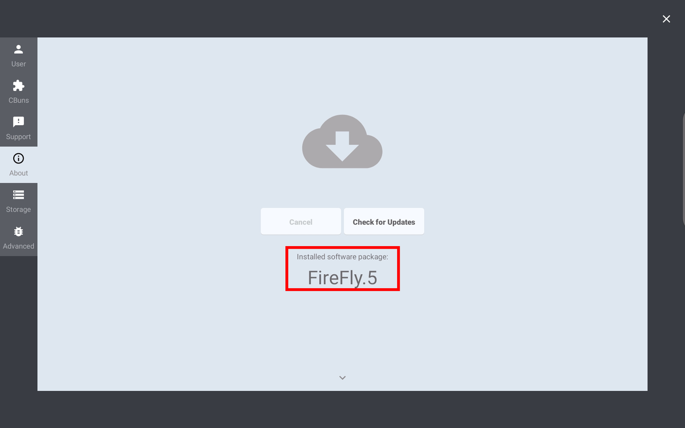
Note: The CBun handshake identifies itself to the Bin Picking Studio server as KASSOW_ROBOTS/1.12.0XXXX. The same 24-byte brand identifier is sent on the Action Request link and on the Robot State Server link. The Vision Controller grants the matching protocol feature set based on this string, so a Bin Picking Studio server supporting the 1.12.0 protocol is required.
General information on CBuns - how they are managed from the teach pendant, the basic interfaces and control items - can be found in the Kassow Robots Software Manual.
The Photoneo Bin Picking Studio delivery consists of a single CBun file and a set of example robot programs:
Core file:
photoneo_bin_picking_studio.cbun |
Example programs:
BPS_Main_Basic.kr2BPS_Main_Basic_Hand_Eye.kr2BPS_Main_Basic_Comm_Check.kr2BPS_Main_Basic_Get_Status.kr2BPS_Main_Basic_Change_BBox.kr2BPS_Main_Basic_Change_Env.kr2BPS_Main_Basic_Change_Sol.kr2BPS_Main_Basic_Multi_VS.kr2BPS_Main_Basic_Reuse_Scan.kr2BPS_Main_Basic_Multiview_Static.kr2BPS_Main_Basic_Multiview_Dynamic.kr2BPS_Get_Object_Pose.kr2BPS_Calibration.kr2BPS_Calibration_Hand_Eye.kr2 |
2 Robot Controller Setup
2.1 Network configuration
The Bin Picking Studio CBun uses two TCP connections:
An outgoing client connection from the robot controller to the Action Request Server running on the Photoneo Vision Controller, default port 11003. All requests described in section 3.2 are sent over this link.
An incoming connection to the Robot State Server, which the CBun starts on the robot controller and which listens on port 11004. The Vision Controller connects to it and receives the live robot joint and flange pose - see section 2.5.
Both devices must therefore be reachable on the same subnet, and traffic must be permitted in both directions. The addressing used throughout this guide is:
Vision Controller IPv4 address: 192.168.1.1 / 24
Robot Controller IPv4 address: 192.168.1.2 / 24
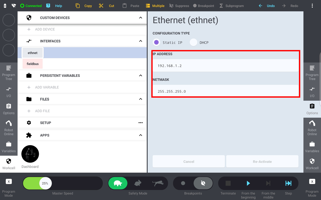
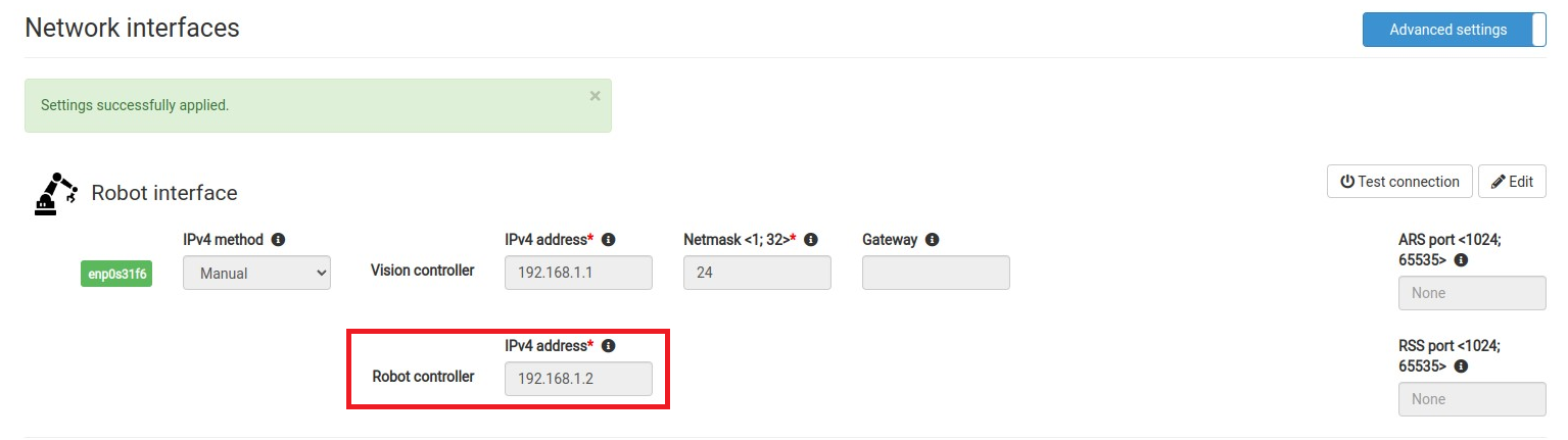
NOTE: Subnet Mask 255.255.255.0 equals a 24 bit subnet mask representation. See this table for more combinations.
2.2 Copying the CBun and example programs to the controller
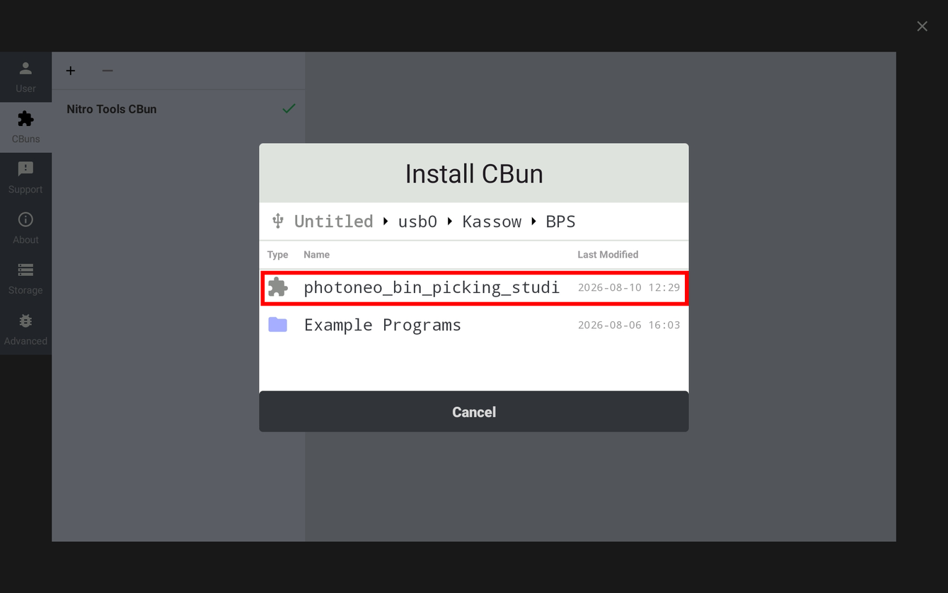
The Robot module files are transferred to the robot controller with a USB stick. Copy the delivered folder structure to the root of the stick and insert it into the USB port of the teach pendant. The file browsers used later in this guide expect the following layout:
usb0 → Kassow → BPS → CBun →
photoneo_bin_picking_studio.cbunusb0 → Kassow → BPS → Example Programs →
*.kr2
Note: The CBun file has to be installed only once per controller. The example programs are loaded individually from the Program → Open dialog and are stored in the controller program storage after the first save.
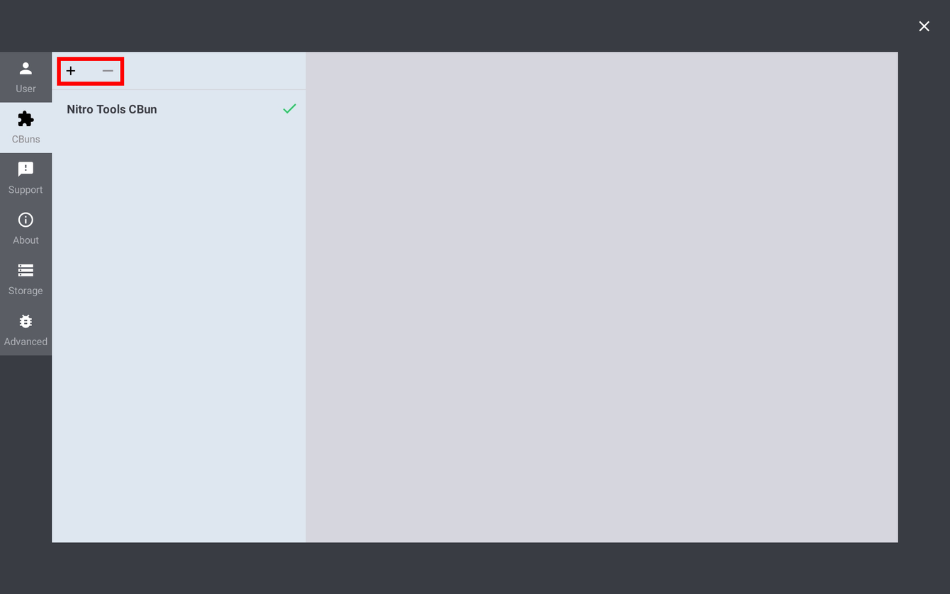
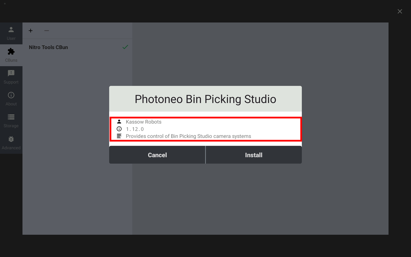
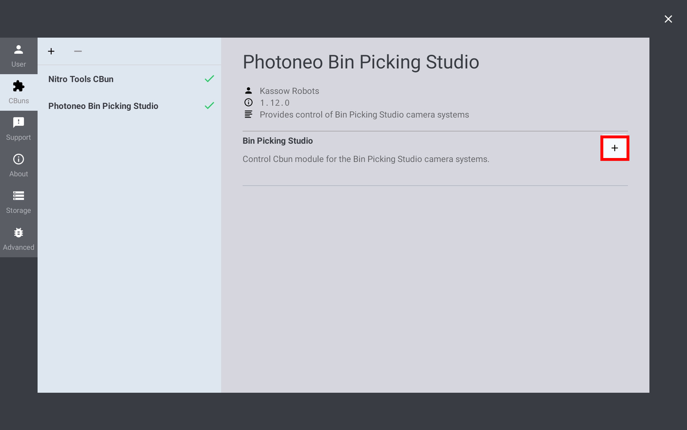
2.3 Installing the Photoneo Bin Picking Studio CBun

2.4 Configuring and activating the Bin Picking Studio device
Adding the device opens its configuration page. The NAME field holds the instance name; the default BINPCK is the prefix that will be shown for every Bin Picking Studio command in the program tree. On the CONFIG tab, enter the connection parameters:
BIN PICKING STUDIO IP ADDRESS - the IPv4 address of the Photoneo Vision Controller (192.168.1.1 in this guide)
PORT - the Action Request Server port, 11003 by default
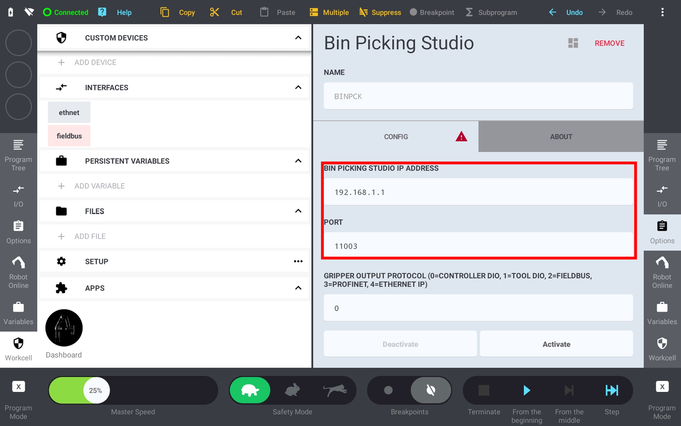

Note: The device configuration is part of the Workcell, not of the program. Remember to save the Workcell (Menu → Workcell → Save) after adding or reconfiguring the Bin Picking Studio device.
2.5 Robot State Server and visualization of the robot pose
Bin Picking Studio needs a continuous stream of the robot state: the joint values are used to visualize the robot and to keep the collision environment up to date, and the Cartesian flange pose is essential for calibration as well as for all Hand-eye scan requests.
On other robot platforms this requires a second, separately configured background task. On Kassow Robots nothing has to be configured - the CBun starts the Robot State Server itself when the Bin Picking Studio device is activated and stops it again on deactivation. It streams, at approximately 10 Hz:
All 7 joint positions [rad]
The flange-centre pose in the world frame: X, Y, Z [mm] and W, P, R [rad]
The server listens on port 11004 of the robot controller and accepts one Vision Controller client at a time.
Note: The reported Cartesian pose is the bare flange (flange to world), independent of any TCP configured in the program. This is why calibration and Hand-eye scan requests need no tool switching on Kassow - see section 2.6.
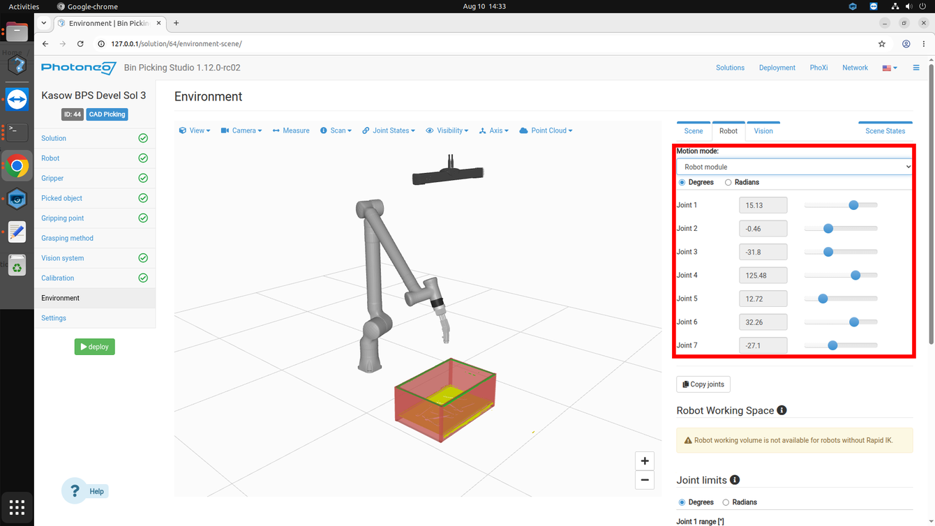
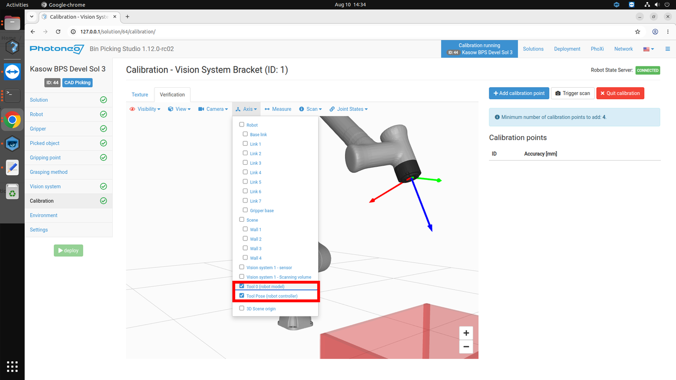
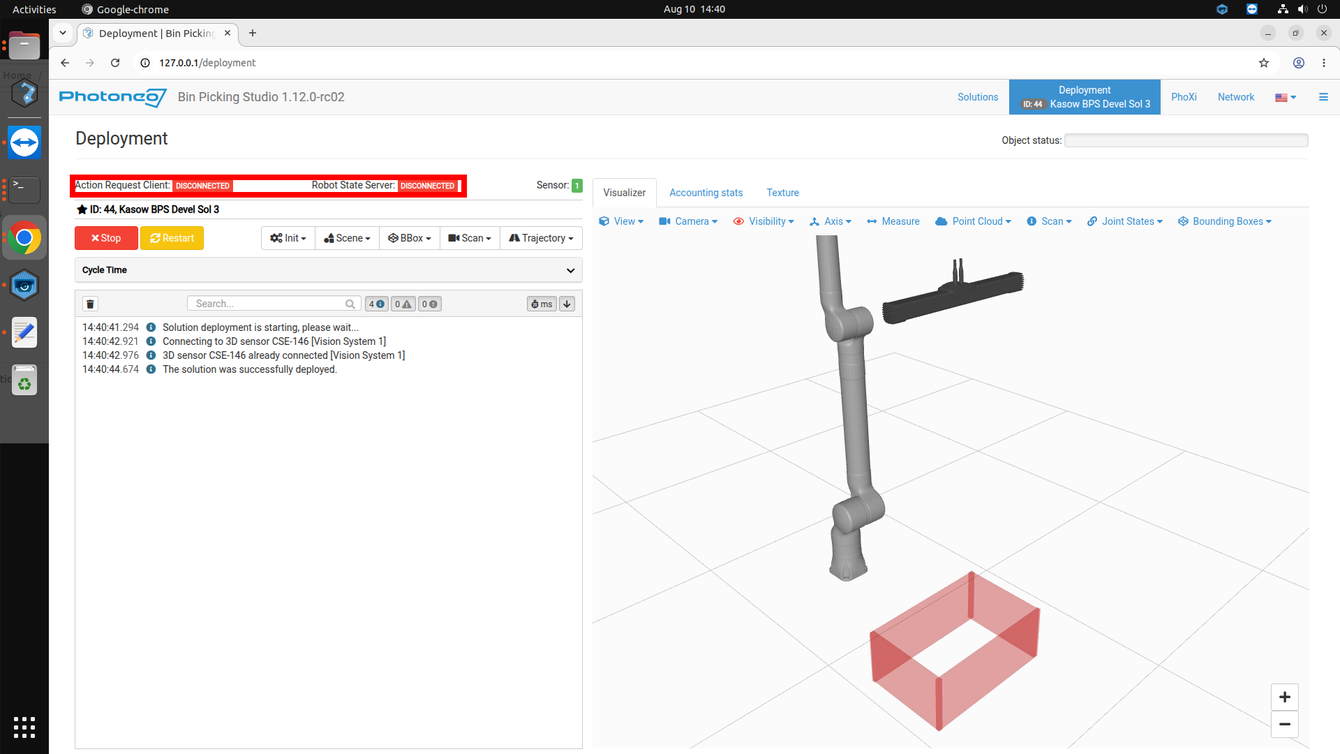
Note: If the Robot State Server row on the Deployment page stays disconnected, check that the Bin Picking Studio device is activated on the pendant and that port 11004 of the robot controller is reachable from the Vision Controller.
2.6 Tool (TCP) and payload setup
Bin Picking Studio is designed to operate with a zeroed tool: it compensates for the tool geometry internally during trajectory calculation, and what it returns to the robot is a joint-space trajectory. The TCP configured in the program therefore does not influence the picking trajectories executed by pho_pick.
The tool frame and the payload still have to be configured, because:
The payload always matters - it is used by the controller for dynamic and safety calculations, and a wrong payload will trigger protective stops or degrade path accuracy.
All motions the robot program owns - the approach and placing moves, and every motion in the
BPS_Get_Object_Poseexample - are executed with the configured tool frame.
For the purpose of this tutorial the example programs use a TCP pose variable named tcp_init and a payload variable named load_init. Before running the robot programs it is therefore necessary to configure both to match the physical construction of the gripper. Ideally this step should be performed before touching up the robot poses.
The example programs set the tool and the payload in the first two instructions of Sequence 1:
SET TCP =
tcp_initSET LOAD2 =
load_init
tcp_init variable in the variable bar at the bottom of the screen to edit the tool frame: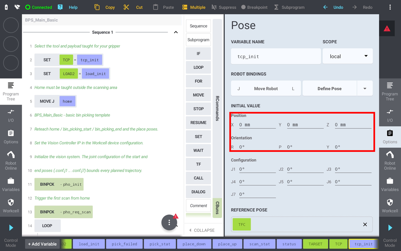
load_init to enter the mass, centre of gravity and inertia of the gripper: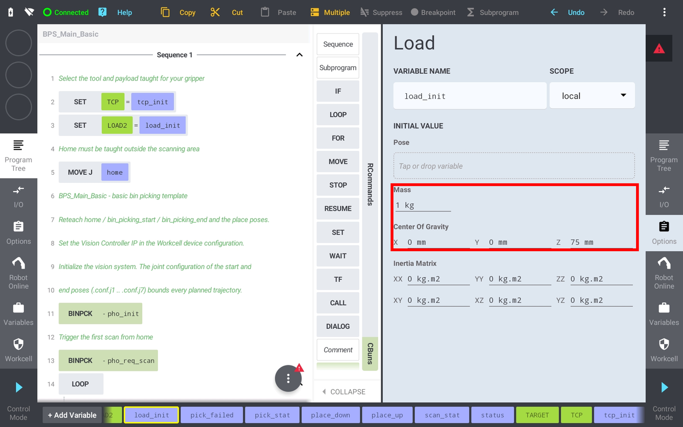
Note: pho_calib_add always reads the current flange-centre pose (flange to world) and is therefore independent of the configured TCP. Hand-eye scan requests are handled the same way, so no tool switching is required around the vision requests themselves - but the picking and placing motions must use the real tool frame.
3 Robot Module
Note: It is strongly recommended to read the Photoneo robotic API prior to this section (user login: customer, password: Ready2LearnHow2Pick).
3.1 Connection to the Photoneo Vision Controller
The connection to the Action Request Server running on the Vision Controller side is opened by the CBun itself when the Bin Picking Studio device is activated - either manually from the device CONFIG page (section 2.4) or automatically when the workcell is loaded. Change the BIN PICKING STUDIO IP ADDRESS field to match the IP address of the Vision Controller you are connecting to; in case of this tutorial it is 192.168.1.1.
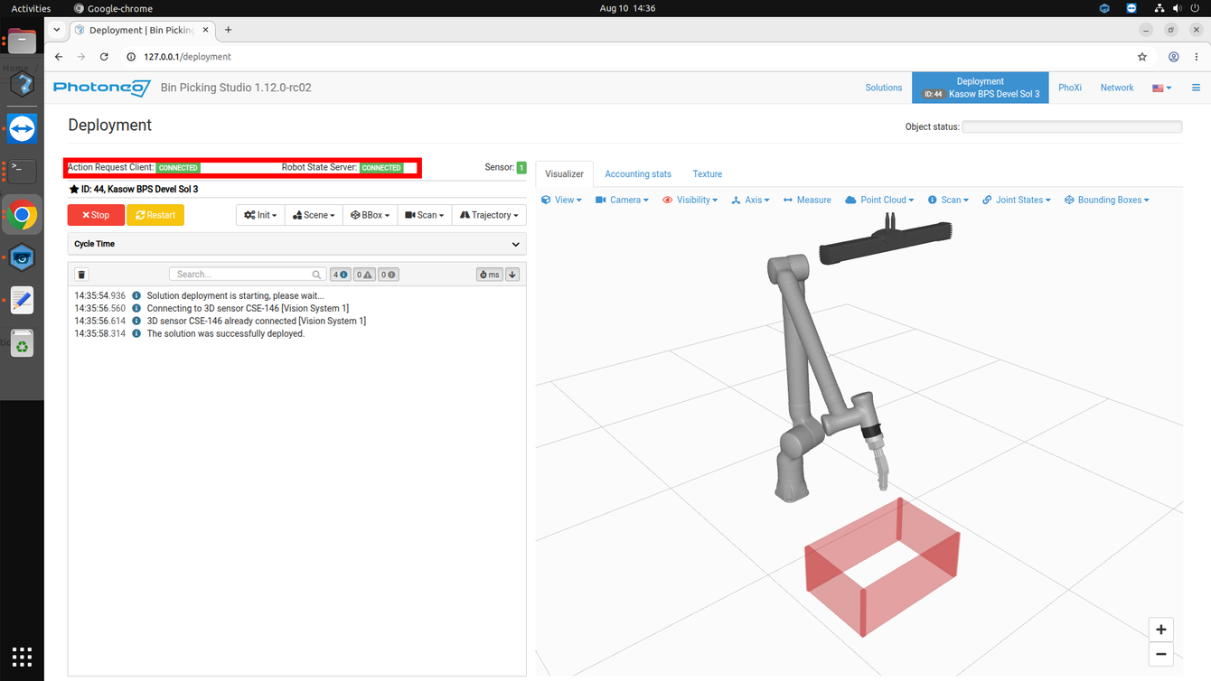
On the robot side, the connection state is indicated by the green check mark on the CONFIG tab of the Bin Picking Studio device. The link can also be verified from the program at any time with the pho_req_comm_check command, which returns response code 0 when the connection is alive - see the BPS_Main_Basic_Comm_Check example program.
3.2 Request List
This section describes the available API calls provided by the Robot module. These commands are inserted into the program tree from the CBuns tab of the command palette and are intended for high-level control of the bin picking application.
Note: The ID column lists the request code sent over the Photoneo communication protocol. pho_pick is a local command that executes the already received trajectory and sends no request to the vision system.
Request |
ID |
CBun command |
Input |
Populates |
|---|---|---|---|---|
Initialize |
4 |
|
Vision System IdStart PoseEnd Pose |
|
Scan (blocking) |
1 |
|
Vision System IdScan Type (Extrinsic / Hand-eye) |
|
Scan Start (non-blocking) |
190 |
|
Vision System IdScan Type (Extrinsic / Hand-eye) |
— |
Wait for Scan |
191 |
|
None |
|
Trigger Scan (MultiView) |
28 |
|
Vision System IdScan Type (Extrinsic / Hand-eye) |
|
Reuse Scan |
29 |
|
Vision System IdScan Type (Extrinsic / Hand-eye) |
|
Trajectory Request |
192 |
|
|
|
Trajectory Receive |
193 |
|
None |
Response CodeTrajectory buffer, operation list, gripper commands, gripping point id, object dimensions and pick-allowed flag, all read back with the
pho_fce_* functions (section 3.5) |
Execute Pick |
local |
|
Fly-by Segment Joint Speed [rad/s]Fine Segment Joint Speed [rad/s]Max Joint Acceleration [rad/s^2]Segment 1..10 Speed [%](all optional)
|
|
Pick Failed |
7 |
|
|
|
Bin Locator |
3 |
|
|
|
Get Object Cartesian Pose |
8 |
|
|
Response CodePose read back with
pho_fce_get_object_pose |
Get Single Object |
8 |
|
Vision System IdPose Mask |
Detected Object PoseResponse Code |
Get Objects |
8 |
|
Vision System IdRequested Object Count (0 = all) |
Object Poses ArrayReturned Object CountObject Info [3 x 100]Response Code |
Get Vision System Status |
21 |
|
|
Localized Object CountNumber Of ReadyProcessing StateResponse Code |
Change Environment Scene |
15 |
|
|
|
Change Bounding Box |
32 |
|
Vision System IdBounding Box Id |
|
Calibration Start |
25 |
|
Solution IdVision System Id |
|
Calibration Add Point |
5 |
|
None (current flange pose is read automatically) |
|
Calibration Save |
27 |
|
None |
Calibration AccuracyCalibration Matrix (RobotPose)Response Code |
Calibration Stop |
26 |
|
None |
|
Change Solution |
9 |
|
|
|
Start Solution |
10 |
|
|
|
Stop Solution |
11 |
|
None |
|
Get Running Solution |
12 |
|
None |
Solution IdResponse Code |
Get Available Solutions |
13 |
|
None |
Solution Id ArrayResponse Code |
Comm Check |
100 |
|
None |
|
Note: pho_req_scan_full performs the scan and waits for the result in a single step. pho_req_scan and pho_wait_scan split the same request into a non-blocking start and a blocking result read, so the robot can move while the Vision Controller is scanning, localizing and planning. Exactly one pho_req_scan may be pending at a time - never issue a second one without collecting the result with pho_wait_scan. The same split exists for the trajectory: pho_req_traj starts the request and pho_recv_traj collects the planned trajectory.
Note: Every request exposes an optional Response Code output parameter. If it is left unbound and the server returns a non-zero code, the CBun raises a program error and the program stops. If it is bound to a program variable, the code is written there and execution continues - which is what the example programs do, so that they can react in-program.
Note: Vision System Id, Bounding Box Id, State Id, Solution Id and Requested Object Count are constant parameters - they take a value typed into the Options panel, not a program variable. Switching between two ids therefore means two separate calls, which is why the switching examples spell out each branch instead of looping over an id variable.
3.3 The bin picking sequence
A complete bin picking cycle consists of five steps:
pho_init- once per Vision System, before the first scan. The joint configurations of the taught Start and End poses (.conf.j1...conf.j7) bound every trajectory Bin Picking Studio will plan.pho_req_scan+pho_wait_scan(or a singlepho_req_scan_full) - trigger the scan, localization and path planning.pho_req_traj- request the trajectory for the next available object.pho_recv_traj- receive the planned trajectory.pho_pick- execute it.
pho_pick replaces the pho_bin_picking procedure known from other Photoneo robot modules: the motion is executed inside the CBun. A single call runs every trajectory segment and performs every gripper operation on the way, using the gripper outputs configured on the BINPCK device (protocol, DIO number, value and settle time per command). The robot program never sees or dispatches a gripper command. The commands themselves are the ones configured on the Grasping method page of the solution:
Gripper Command |
Meaning |
What |
|---|---|---|
1 |
Attach |
Writes the Gripper Attach output configured on the BINPCK device (DIO number and value) and waits out the configured settle time. |
2 |
Detach |
Writes the Gripper Detach output configured on the BINPCK device - it may be a different DIO number than attach. |
3, 4, 5 |
User 1, User 2, User 3 |
Optional auxiliary operations, configured on the Grasping method page of the solution (blow-off, second vacuum zone, …); each has its own output configuration on the device. |
Two properties of pho_pick are worth remembering:
The gate is single-shot. When
pho_pickreturns, the received trajectory is discarded, so a stale trajectory can never be executed twice - request and receive a new one before the next pick. Callingpho_pickwithout a received trajectory returns response code 201.A failed pick should be reported. If
pho_pickreturns a non-zero response code, callpho_send_pick_failedso Bin Picking Studio can update its internal state and re-plan for the remaining objects, then move back to home and rescan.
A program that prefers to run its own motion loop can still read the received trajectory out point by point with the pho_fce_* functions listed in section 3.5. pho_pick is the convenient path, not the only one.
3.4 Speed and blending parametrization
Bin Picking Studio supports up to 10 trajectory segments per single bin picking trajectory. The default number of segments is 4 (Start to Approach, Approach to Grasp, Grasp to Deapproach, Deapproach to End); if needed, additional segments can be configured on the Grasping method page in the BPS solution.
The motion parameters are all optional parameters of pho_pick, in two layers: three cell-wide speeds, and a percentage per segment on top of them. Every trajectory segment is executed in joint space.
Layer 1 - the cell-wide speeds, which apply to the whole pick:
Fly-by Segment Joint Speed[rad/s] - maximum joint speed for segments that end in a blended (fly-by) point. Default 0.6 rad/s.Fine Segment Joint Speed[rad/s] - maximum joint speed for segments that end in an exact (fine) point, typically the grasp itself. Default 0.3 rad/s.Max Joint Acceleration[rad/s^2] - maximum joint acceleration used for blending. Default 2.0 rad/s².
Bin Picking Studio marks each planned segment as fine or fly-by, and pho_pick applies the matching speed automatically. Leave the three parameters unbound to use the conservative defaults, or bind them to program variables to tune the cell.
Note: The third parameter is labelled Max Joint Acceleration and is an acceleration limit, not a blending radius. Blending itself is derived from it by the controller.
Layer 2 - Segment 1..10 Speed [%], one optional percentage per trajectory segment. Each scales both the joint speed and the joint acceleration of that segment, so a scaled segment is a pure slow-motion replay of the same path rather than a path with a different blending behaviour. This is the per-segment array known from the other Photoneo robot modules, and the segment numbering is the same one ABB indexes pho_speeddata{trajectory_ID} with, so an existing configuration ports across directly. With the default 4-segment grasping method:
Segment 1 Speed[%] - Start to Approach, the transfer into the bin.Segment 2 Speed[%] - Approach to Grasp, the segment usually worth slowing down; 25-50 % is a typical starting point.Segment 3 Speed[%] - Grasp to Deapproach, lifting the picked part out.Segment 4 Speed[%] - Deapproach to End, the transfer towards the place pose.
The rules are deliberately forgiving, so a half-configured program still runs the way it was tested:
Unbound - or bound to a variable that is still 0 - means 100 %, i.e. exactly the layer 1 speeds. Nothing has to be filled in to keep the current behaviour.
Values are clamped to 1..100 %. A percentage can only slow a segment down and can never exceed the speeds tuned in layer 1, so a mistyped 1000 cannot speed the robot up. To run faster, raise the Fly-by / Fine Joint Speed instead.
Segments beyond 10 - which Bin Picking Studio does not plan - run unscaled.
The percentages are read once when
pho_pickstarts, so changing a bound variable during the pick has no effect until the next one.
These are Number parameters, so each one is bound to a program variable rather than typed in as a literal: declare a Number variable, Set it once near the top of the program, and bind it to the segment. Scaling only the grasp segment therefore costs one variable and one Set instruction: declare a Number called grasp_pct, add Set grasp_pct = 30 before the picking loop, and bind it to Segment 2 Speed [%] in the Options panel of pho_pick. Every other segment is left unbound and keeps running at the full layer 1 speed.
For the first commissioning run, leave every parameter unbound and use the Master Speed slider on the pendant to scale the whole program down - see section 4.7. Reach for the per-segment percentages afterwards, once the pick works end to end and the goal is cycle time: raise the layer 1 speeds until the transfers are as fast as the cell allows, then bring the grasp segment back down with its percentage.
3.5 Trajectory and object data functions
In addition to the program commands listed above, the CBun provides value functions that can be used directly inside expressions - for example in an IF or LOOP condition, or on the right-hand side of an assignment - without inserting a separate program step. The trajectory functions read out the data received by the last pho_recv_traj:
Function |
Input |
Returns |
|---|---|---|
|
None |
Number - number of operations in the trajectory received by the last |
|
Operation Index |
Number - operation type of the given operation (move trajectory or gripper command) |
|
Trajectory Index |
Number - number of points in the given trajectory |
|
Trajectory Index |
Number - joints per point as sent by Bin Picking Studio (7 for a Kassow arm) |
|
Trajectory Index |
Number - 1 if the trajectory ends with a fine (exact) target, 0 otherwise |
|
Trajectory Index
Point Index
Joint Index
|
Number - single joint angle of the given trajectory point [deg] |
|
Gripper Index |
Number - gripper command of the given gripper operation |
|
None |
Number - 1 if a trajectory has been received and not executed yet, 0 otherwise |
|
None |
Number - gripping point ID of the object in the last received trajectory |
|
None |
Number - X dimension of the object in the last received trajectory [mm] |
|
None |
Number - Y dimension of the object in the last received trajectory [mm] |
|
None |
Number - Z rotation of the object in the last received trajectory [mrad] |
|
None |
RobotPose - raw Cartesian pose requested by the last |
|
Vision System Id |
Number - count of localized objects awaiting processing |
|
Vision System Id |
Number - total count of detected objects, including rejected ones |
|
Vision System Id |
Number - 0 when processing is complete, 1 while recognition is running |
|
None |
Number - ID of the currently deployed solution |
3.6 Example Programs
Several example programs are delivered with the Photoneo Kassow module. They demonstrate how to properly use the requests listed in section 3.2 for various use cases:
Example program |
Description |
|---|---|
|
The basic bin picking template - start here. It demonstrates the complete workflow:
pho_init bounds the planning volume with the joint configurations of the taught start and end poses, pho_req_scan / pho_wait_scan trigger the scan, localization and path planning, pho_req_traj / pho_recv_traj fetch the planned trajectory and pho_pick executes it segment by segment.The next scan is triggered before the placing motion, so localization and planning of the following object overlap with the place movement and the cycle time drops.
Every request writes its result into a status variable, so the program can react in-program instead of aborting.
NOTE: make sure that
bin_picking_start and bin_picking_end are correctly taught - they define the volume Bin Picking Studio plans in. |
|
Same as |
|
Same as |
|
Same as
BPS_Main_Basic, but with pho_req_get_status calls added to the loop. The request can be called repeatedly in short intervals during the localization phase and returns:Localized Object Count - number of objects localized
Number Of Ready - number of objects ready for picking
Processing State - 0 when processing has finished, 1 while object recognition is still running
These values are commonly used for advanced decision making, in particular to determine the optimal moment for starting the pick procedure.
|
|
Same as |
|
Same as |
|
Same as |
|
Same as |
|
Same as the
BPS_Main_Basic_Multi_VS example but introduces pho_req_reuse_scan. This request is particularly useful when the scene has not changed since the last scan but localization has to run again with a different configuration - searching for a different object, using a different bounding box or different settings.Procedure: perform a regular scan for VS1 to capture the scene, then use
pho_req_reuse_scan for VS2 to reuse the image data from VS1. This repeats the localization with a different configuration without acquiring new data. |
|
Static MultiView (meshing) example. It shows stitching of multiple scans before localization is started, which is particularly useful for complex scenes or large objects. It uses a static approach, where the robot stops at each scanning position to trigger and capture a scan.
Procedure: move through all scanning poses (
scan_pose_1 - scan_pose_3) and make sure pho_req_capture is called in each of them. After the capture sequence is complete, start localization with pho_req_scan_full. This request does not perform an actual scan and emits no light; it only triggers localization and planning on the accumulated data.Scan limit: keep the total number of scans below 10 to ensure optimal system performance.
|
|
Dynamic MultiView example, demonstrating Photoneo Instant Meshing. It leverages the MotionCam-3D Parallel Structured Light technique to capture multiple scans while the robot is moving, accumulating 3D data into a single point cloud without stopping.
The implementation uses a second program sequence running in parallel with the motion sequence. Sequence 1 raises the
meshing_on flag before the scanning trajectory and clears it at the end; Sequence 2 loops on that flag and issues pho_req_capture every meshing_gap seconds. Localization is then started with a single pho_req_scan_full.Requirements: MotionCam-3D is required for Instant Meshing (standard PhoXi 3D Scanners do not support dynamic scanning). In the BPS solution
pho_mesh_dynamic must be set to True and pho_capture_gap is recommended at approximately 500 ms.Trajectory control: keep the scanning trajectory smooth and the bin inside the scanner field of view to prevent tracking loss.
|
|
Localization only, without Bin Picking Studio path planning. Instead of requesting a trajectory the robot retrieves the Cartesian pose of the object with
pho_req_get_object and owns all motion itself. This is useful for pick verification, slip sheet detection and conveyor picking tasks.The system returns the raw Cartesian pose from localization. The origin is defined by the object’s CAD / STL file; no gripping points and no invariance transformations are applied.
NOTE: collision-free path planning is NOT provided in this mode. The approach and retract motions in the example are plain MOVE instructions derived from the object pose.
|
|
Automatic calibration procedure for a statically mounted scanner (sphere or marker pattern, Extrinsic).
Requirements: the initial calibration of the Vision System must be started and confirmed manually by the user on the Bin Picking Studio side.
Calibration steps: teach all 9 calibration poses (P1 - P9). Points can be added to the calibration table manually by clicking “Add Calibration Point” on the Bin Picking Studio side, or by calling
pho_calib_add directly from the program.Calibration accuracy: the general rule is that the calibration error should remain below 3 mm. Higher errors typically indicate a systematic issue in the calibration setup.
Automatic recalibration (optional): once the first calibration is successful and automatic recalibration is enabled in the Vision System settings, use
pho_calib_start, pho_calib_add, pho_calib_save and pho_calib_stop to manage the recalibration cycle.Important: the calibration object - either a ball or a marker pattern - must remain in its original position to ensure successful automatic recalibration.
The program retracts through the taught poses P10 - P13 after
pho_calib_stop. Reteach or delete those moves for your cell. |
|
The same automatic calibration procedure for a carried, hand-eye mounted scanner (marker pattern based calibration). |
4 Runtime
Once the solution is fully configured on the Vision Controller side, it is time to finalize the remaining steps on the robot side and proceed to executing the BPS_Main_Basic program.
4.1 Loading an example program
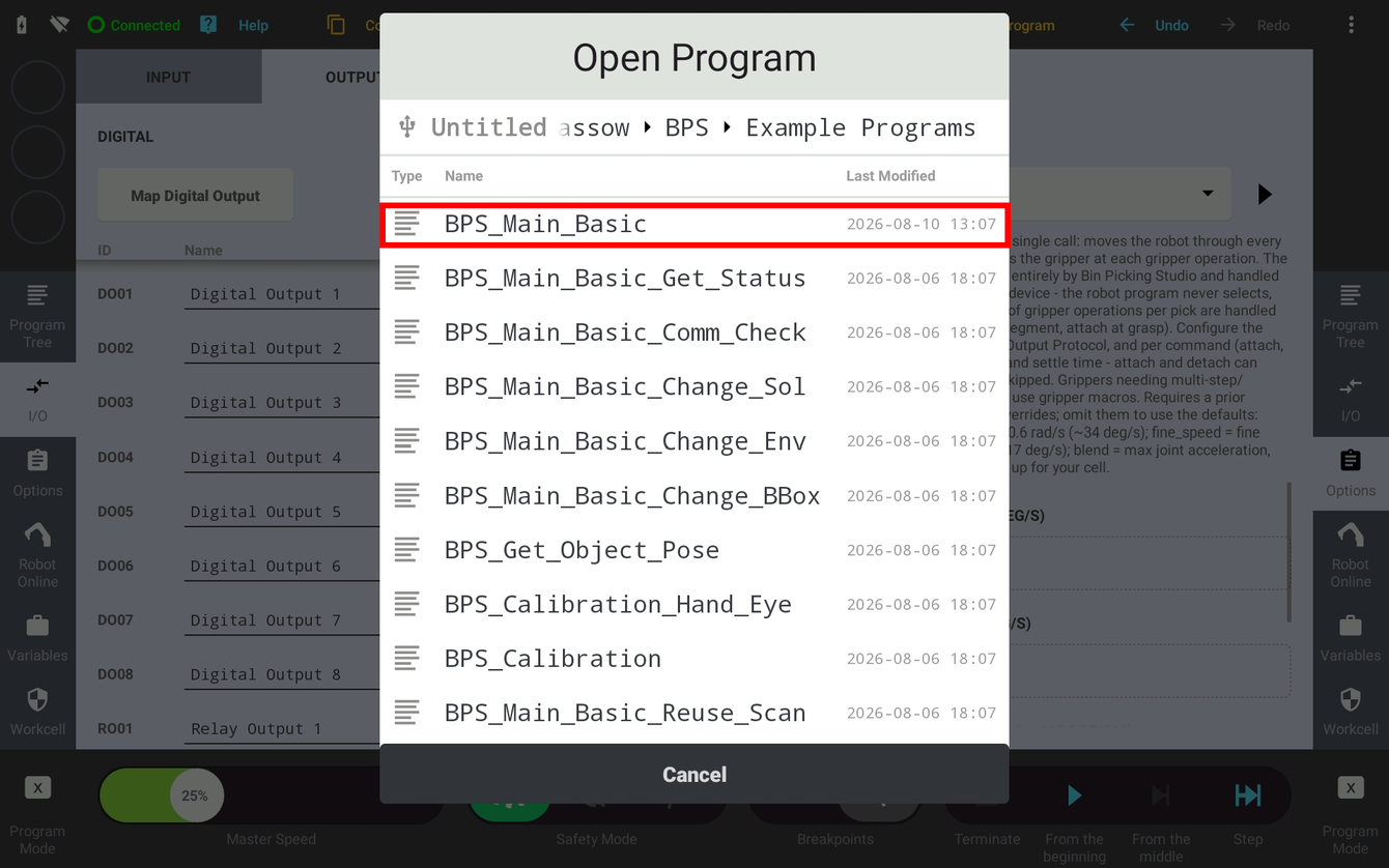

4.2 Program structure
All main example programs follow the same structure. Using BPS_Main_Basic as the reference:
SET TCP =
tcp_initand SET LOAD2 =load_init- set the tool frame and the payload (see section 2.6)MOVE J
home- move out of the field of view of the scanner, before anything is requested from the Vision ControllerBINPCK
pho_init- initialize Vision System 1 withbin_picking_startandbin_picking_endBINPCK
pho_req_scan- trigger the first scan from homeLOOP - the endless Pick and Place loop
BINPCK
pho_wait_scan- wait for scan, localization and path planning to finishBINPCK
pho_req_traj- request the trajectory for the next pickable objectMOVE J
bin_picking_start- move to the start pose while Bin Picking Studio is planningBINPCK
pho_recv_traj- receive the planned trajectoryBINPCK
pho_pick- execute the whole pick in one call; the gripper is actuated inside the CBun from the device’s gripper IO configurationPlacing - MOVE J
place_up, MOVE Lplace_down, then BINPCKpho_req_scanfor the next cycle: the robot is out of the scanner’s view at the place pose, so localization and planning overlap with releasing and retreatingSET DO1 = 0, WAIT, MOVE L
place_up- release and retreatError paths - on a failed pick (plus BINPCK
pho_send_pick_failed), a failed plan or an empty scan, MOVE Jhomefirst and only then rescan
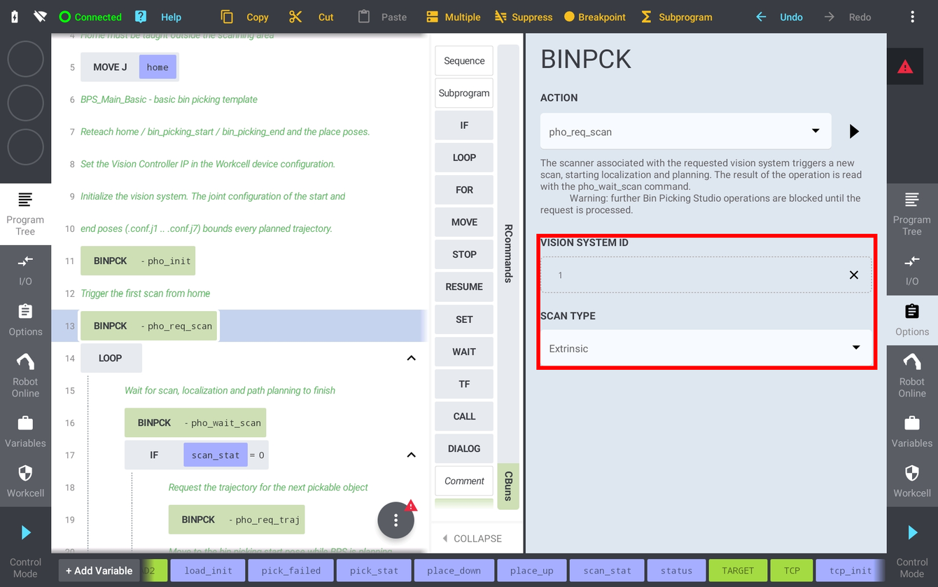
pho_init takes the Vision System Id and the two taught poses that bound the planning volume: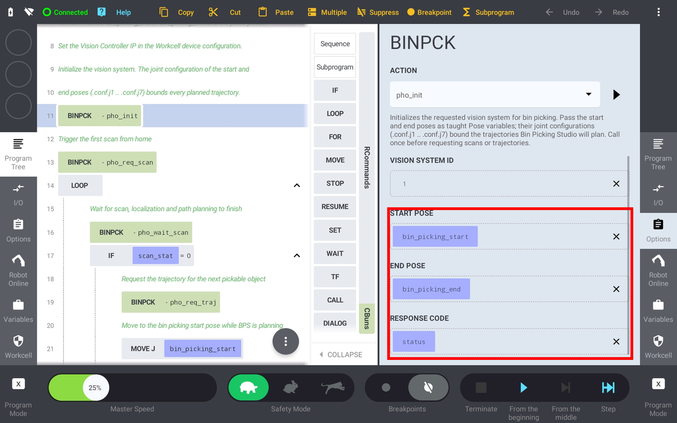
pho_pick exposes the Response Code plus the optional motion parameters described in section 3.4 - the three cell-wide speeds and the ten per-segment percentages. There are no gripper parameters, because the gripper is actuated inside the CBun: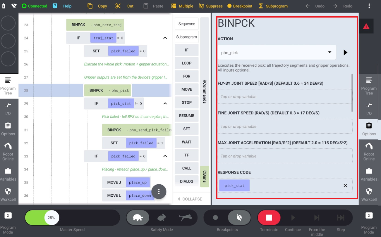
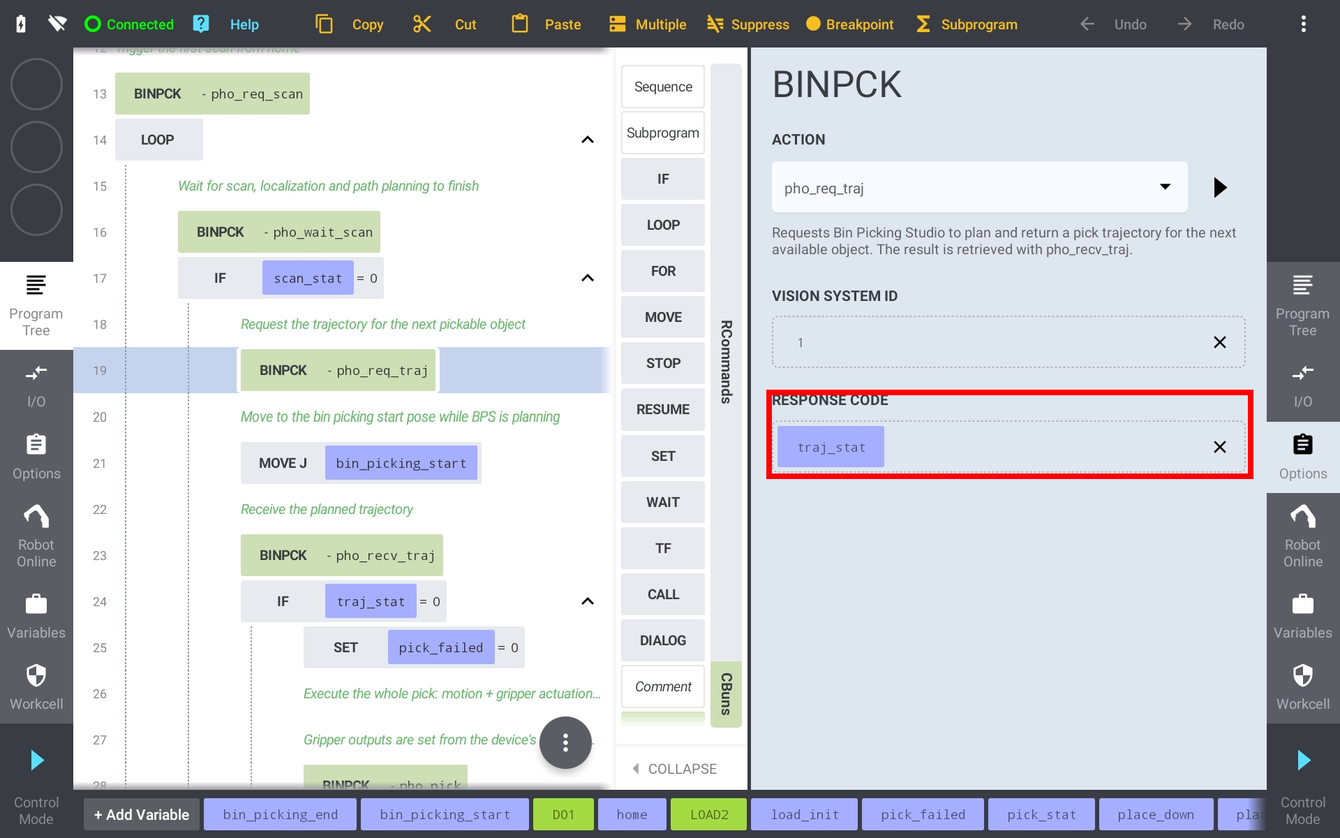
4.3 Gripper commands
Bin Picking Studio decides when a gripper operation happens - the Grasping method page of the solution defines which gripper command is executed at each major trajectory waypoint - and pho_pick performs it inside the CBun. Configure the outputs once on the CONFIG tab of the BINPCK device: the output protocol (Controller DIO, Tool DIO, Fieldbus, PROFINET, EtherNet/IP) shared by all commands, and the DIO number, the value and the settle time for Attach, Detach and User 1..3 separately.
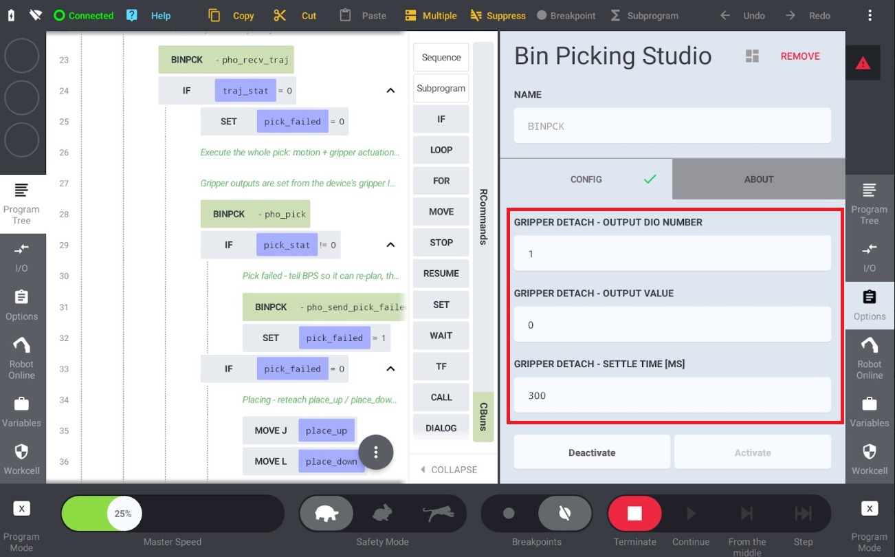
pho_pick dwells after switching the output, so the gripper physically releases before the next segment moves off: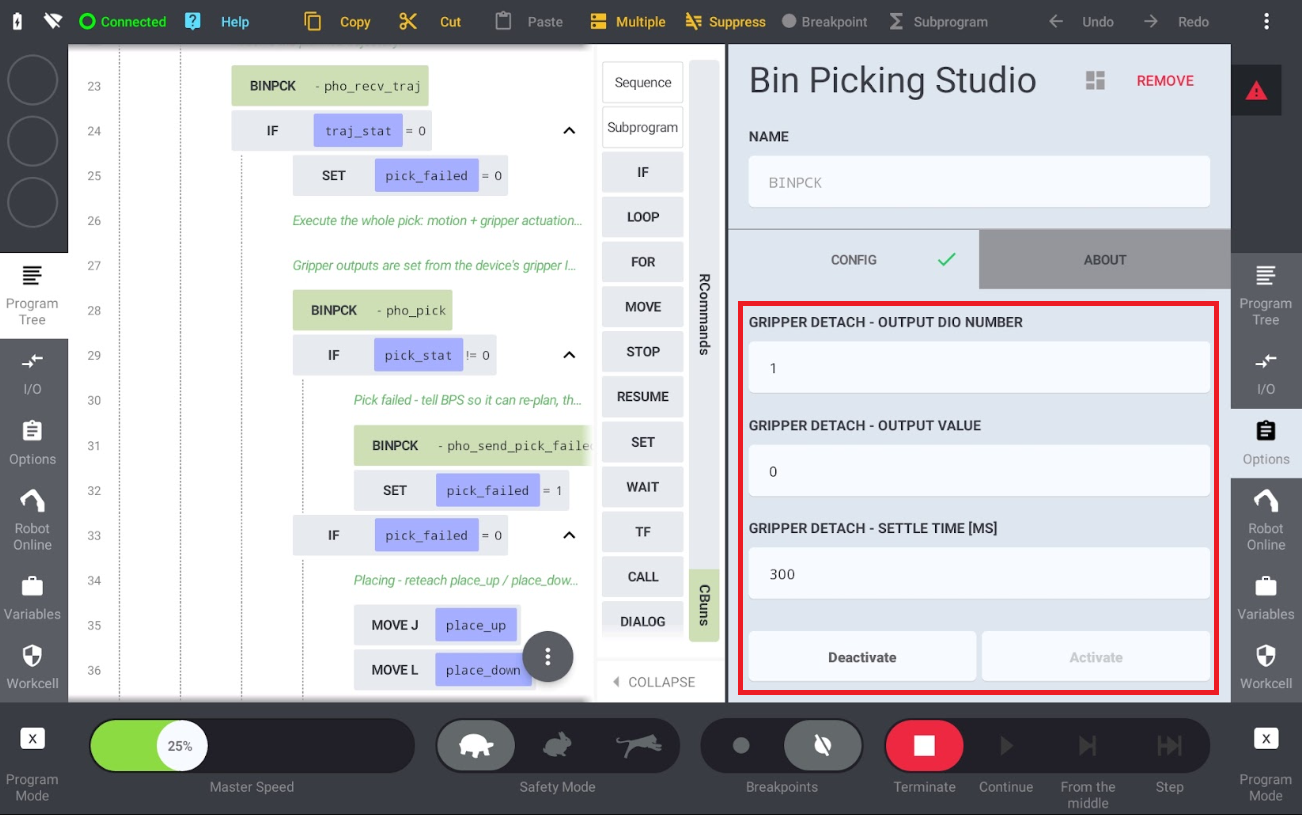
pho_pick releases automatically: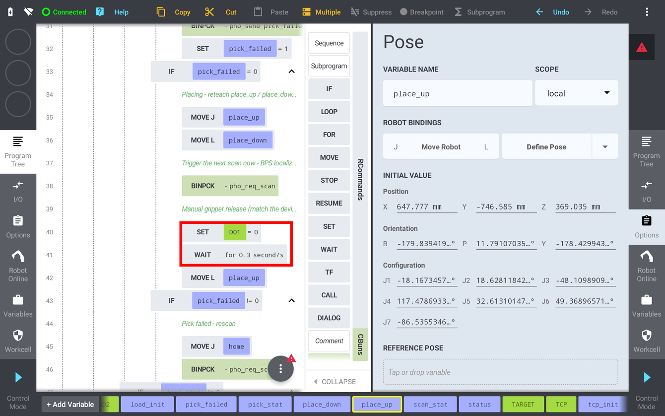
pho_pick will write the configured attach output after reaching the Grasp waypoint: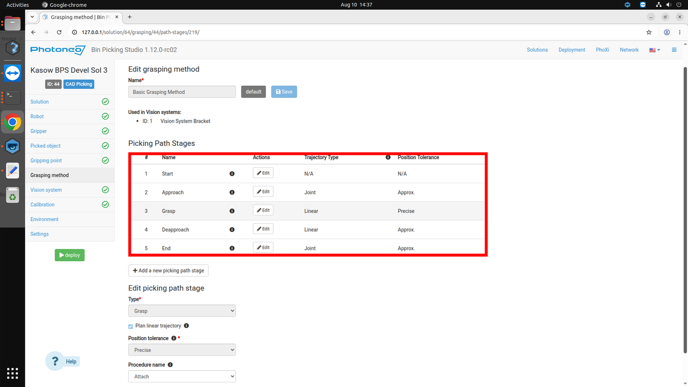
4.4 Teach Positions
After opening BPS_Main_Basic or another template, there are a couple of poses that need to be touched up before running the program:
home- the scanning / waiting pose. Must be taught so that the robot is out of the field of view of the scanner.bin_picking_startandbin_picking_end- essential for all Vision Systems used in the current solution. They define the initial and final trajectory waypoints required during the initialization and bound the planned trajectories. Usually touched up above the centre of the bin.bin_picking_start_2andbin_picking_end_2- the same pair for the second Vision System in the Multi VS and Reuse Scan examples.place_up/place_down- the placing position;place_downis the drop point andplace_upis the retract pose above it.scan_pose- the scanning pose of the Hand-eye example, from which the scan request is issued.scan_pose_1…scan_pose_3- the additional scanning waypoints used by the MultiView examples.Calib_Start, P1 … P9 - the calibration start pose and the nine calibration poses used by the calibration programs; P10 … P13 are the retract path ofBPS_Calibration.
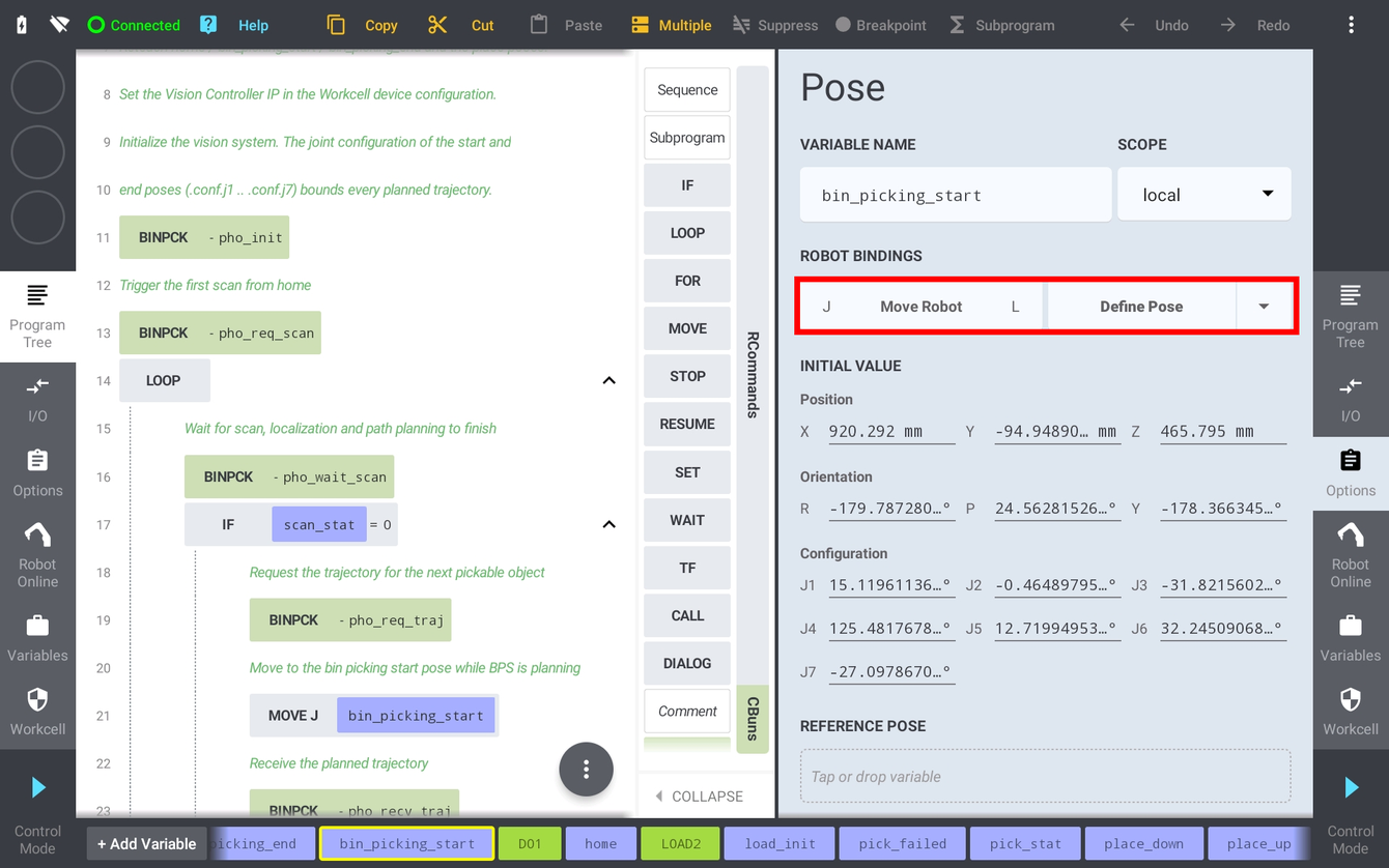
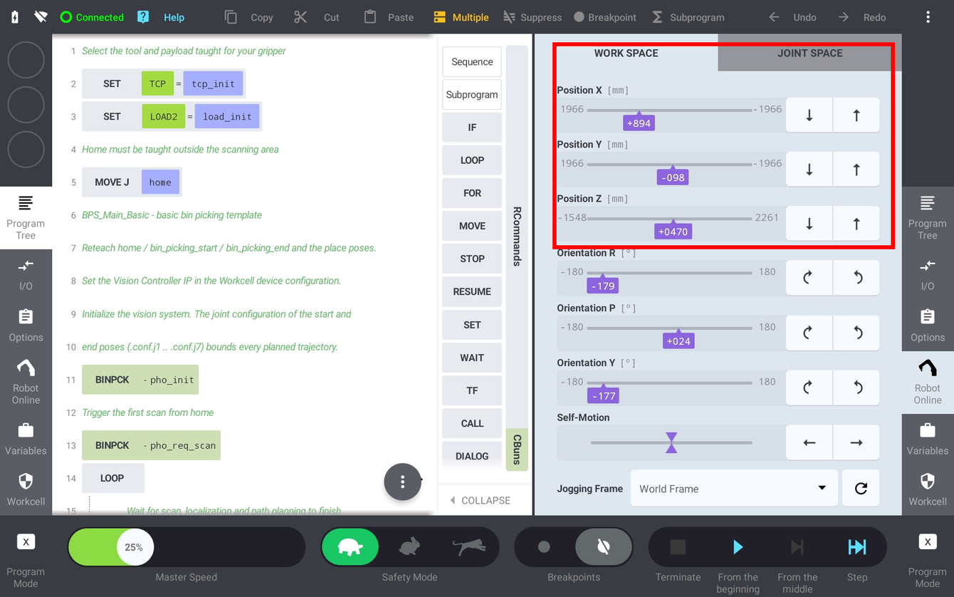

Note: Kassow robots have 7 joints, so a Cartesian pose does not uniquely define the arm posture. The joint configuration stored with the pose (J1 - J7) resolves the redundancy. This matters twice over for bin picking: it is why poses should always be taught by jogging the real robot rather than by typing in coordinates, and it is what pho_init sends to Bin Picking Studio as the bounds of the planning volume.
pho_pick are not affected by these settings; they are parametrized as described in section 3.4:
4.5 Calibration
There are 2 methods of calibration available in Bin Picking Studio:
Sphere based calibration - for statically mounted sensors
Marker pattern based calibration - for carried or Hand-eye mounted sensors
For both methods it is required to capture a calibration object from 9 poses with sufficient variance in tool pose data. On Kassow Robots the pose sent to the Vision Controller is always the bare flange pose in the world frame (section 2.5), so no tool or reference frame has to be zeroed manually - but the poses still have to be varied in orientation, not just in position.
The calibration procedure can be done directly without using the Kassow module calibration programs. This can be achieved by starting Calibration on the Bin Picking Studio side, jogging the robot from point to point and manually adding the points on the Bin Picking Studio side. However, for production setups where recalibration is expected, it is recommended to record the calibration points into the program and to ensure that the transition between these poses is collision free.
The Kassow module provides two programs for the automated calibration process:
BPS_Calibration- calibration procedure for a statically mounted sensorBPS_Calibration_Hand_Eye- the same procedure for a carried, Hand-eye mounted sensor
pho_calib_add in each of them and finish with pho_calib_save and pho_calib_stop. They therefore enable automatic recalibration without touching the Bin Picking Studio system at all. The procedure starts with pho_calib_start, which takes the solution and vision system to calibrate: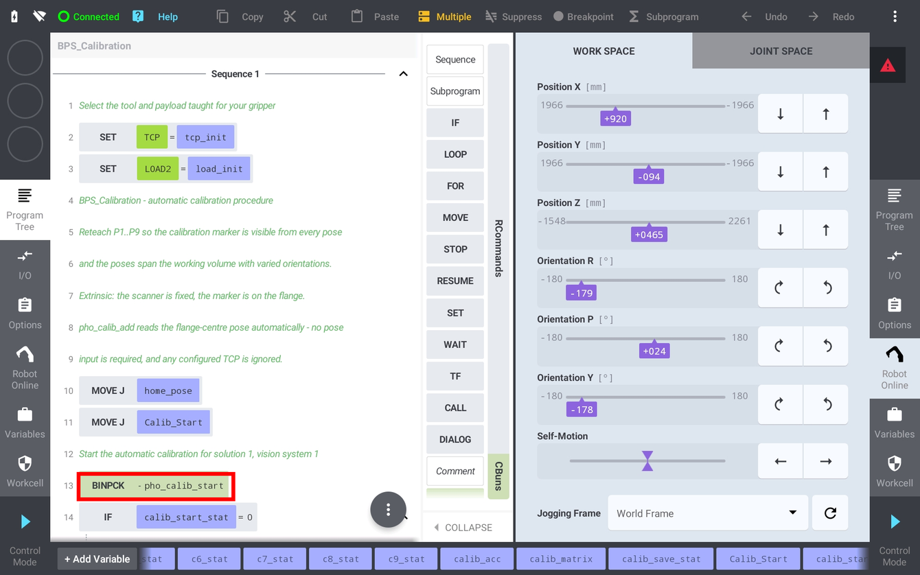
pho_calib_save also returns the achieved Calibration Accuracy and the resulting Calibration Matrix, so the program can log or check them: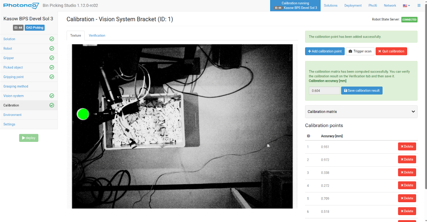
In general the calibration error should be below 3 mm. Use the verification tab to check if the point cloud overlay over the robot body or gripper matches perfectly. Any discrepancy needs to be investigated because it can lead to a collision. The most common issues are: wrong tool frame values, incorrect gripper model orientation, incorrect robot model selection, encoder zeroing and a flimsy robot base.
4.6 Runtime Prerequisites
Final pre-deployment check before running the bin picking interface from the robot side. Make sure that:
The Bin Picking Studio solution is properly configured on the Vision Controller side, including the environment and the grasping method
The network setup on the robot side is completed, the Bin Picking Studio device is activated and the Robot State Server shows CONNECTED
All Vision Systems defined in the solution are calibrated
The tool frame (
tcp_init) and the payload (load_init) match the physical gripperThe Start and End poses for all Vision Systems have been touched up
All local poses in the main program have been touched up properly
Gripper commands are prepared and working
4.7 Running the BPS_Main_Basic program
NOTE: It is strongly recommended to decrease the Master Speed to a low value - for example 25% - before running the program for the first time. The Master Speed slider is located in the lower left corner of the teach pendant in Program Mode.
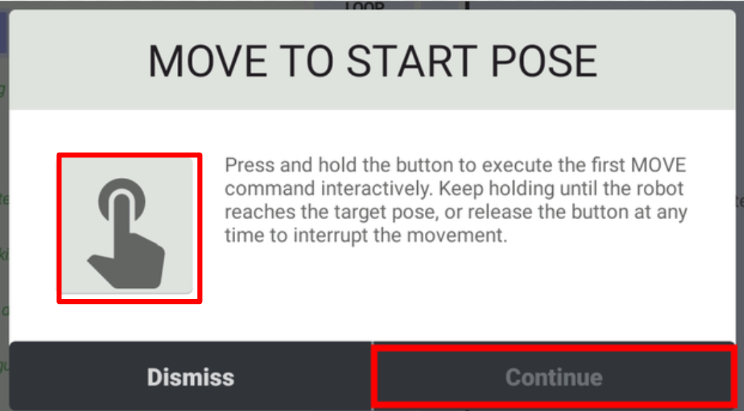

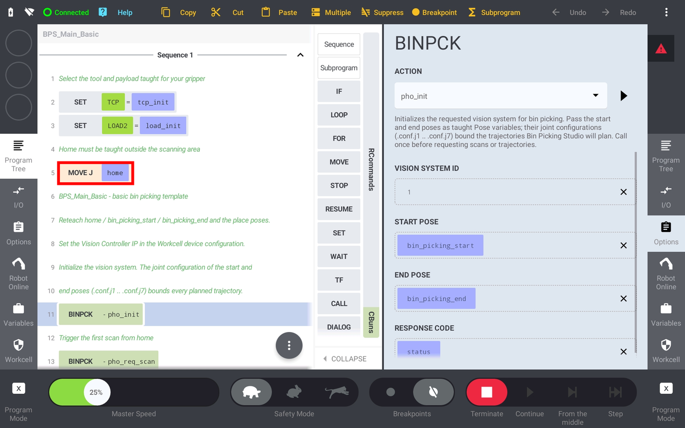
If there is a pickable object in the scene and the trajectory for the first object has been received by the robot controller, the robot starts moving towards the first object.
If everything looks fine, keep moving the robot towards the first target and check that the path is correct. At this point, if the robot is too far from the object or pushes the object too deep, then make modifications on the Bin Picking Studio Tool Point or Gripping Point pages - not in the robot program.
pho_pick speeds if needed (section 3.4) and slowly ramp the Master Speed back up to 100%. Tune in that order: first raise the two cell-wide joint speeds until the transfer segments are as fast as the cell allows, then bring individual segments back down with their Segment N Speed [%] percentage - usually only the grasp segment needs it.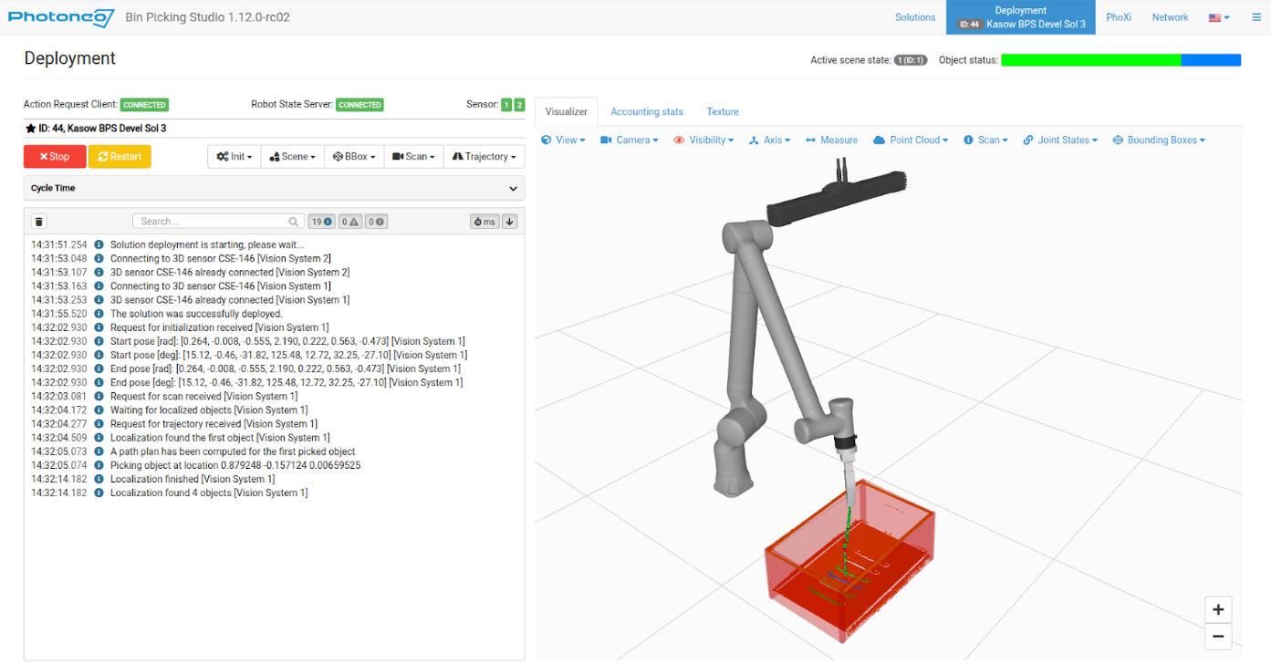
Congratulations, you have successfully deployed the Photoneo Kassow Robots Bin Picking Studio interface. You can now focus on improving your application further. Use the Kassow BPS 1.12.0 Quick Reference workbook delivered next to this guide and the example programs as your guidelines.
5 Contact Information
Headquarters:
Zebra Technologies Slovakia s.r.o.
Plynárenská 6
821 09 Bratislava,
Slovakia
|
Technical support
Contact us at the Help Center.
Visit Photoneo support pages at www.photoneo.com/support.
Orders and inquiries:
|