CAD file
A CAD file is the best input for smaller rigid objects that are picked from a bin in random orientations. Because the object can lie in any orientation, the engine needs a full 360° model of it. For the other input, see Mesh tools. To compare the two, see Localization inputs.
Requirements
A bad model gives a bad localization. Check the file before you upload it:
STL format – the input is an STL file. Export it from your CAD software.
Units in millimeters – the model must be at its real size, in millimeters. A model exported in meters or inches has the wrong scale, and the engine does not find the object.
Not corrupted – the mesh must be complete and clean: no missing or broken faces, no holes and no extra parts that do not belong to the object.
Normals point outward – every triangle’s normal must point out of the object, not inward. Inverted normals can stop the engine from finding the object. In the visualizer they make the model look dark or inside out.
Origin in a sensible place – put the origin of the model inside or on the object, for example at its center or at a corner. Do not leave it far away from the model (for example 5 m to the side). The origin is the reference for symmetry, model features and gripping points, so a distant origin makes it hard to turn and move the model when you set up the gripping points.
If the model has inverted normals or a bad origin, you can fix them in the Studio with Normal re-orientation and Origin transformation. It is still better to fix the model in your CAD software.
Uploading the file
Open the Picked object step of the solution.
In the CAD model field, click Browse… and select your STL file.
The model appears in the 3D visualizer. Check it:
Size – under the visualizer, Size [mm] shows the size of the model. It must match the real object. A model that is 1000 times too small or too big was exported in the wrong units.
Normals – the model must not look dark or inside out.
Origin – use View > All to see the whole model and check where its origin is.
If the model needs clean-up, use the mesh tools.
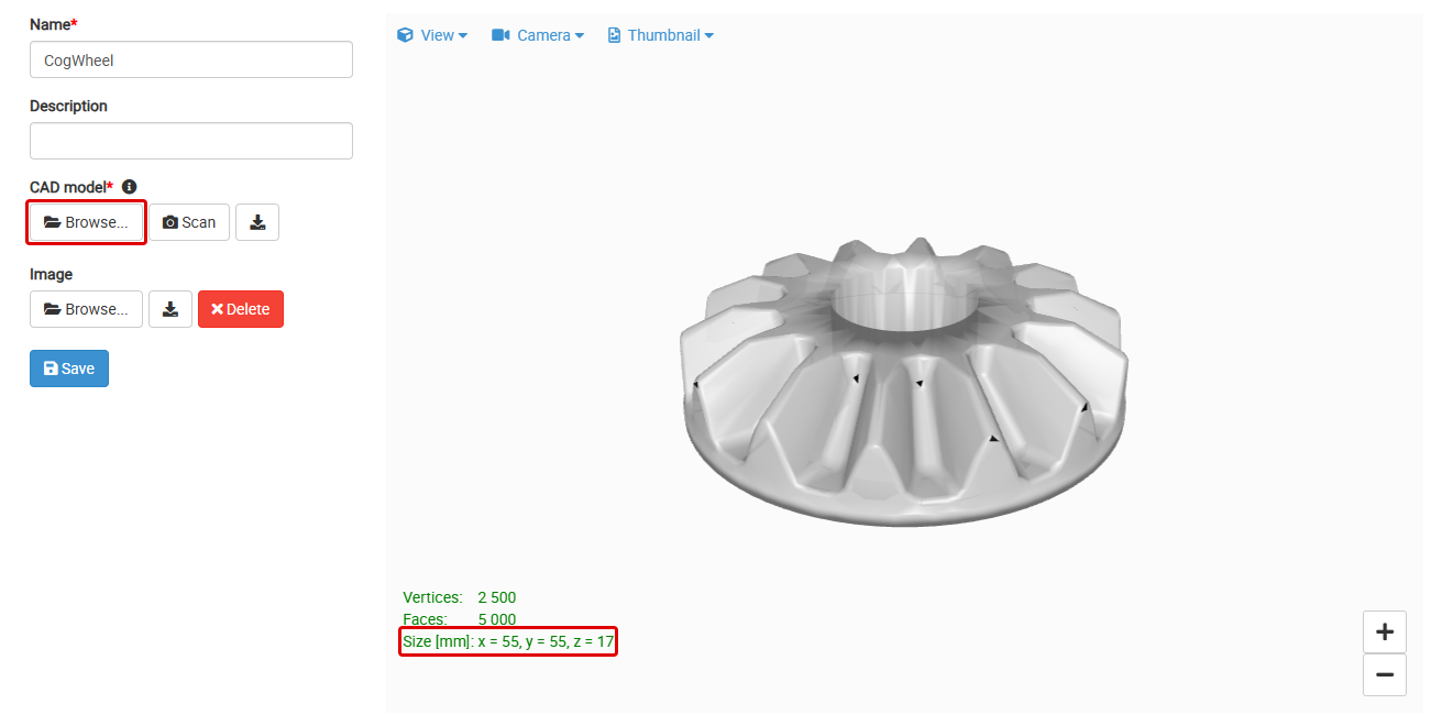
The Picked object page with the uploaded cogwheel model. Upload the STL file with Browse… and check its size under the visualizer.
Changing the origin in Locator Studio
In a CAD Localization solution (Locator Studio), you can move the origin of the model right on the Picked object page, without editing the file:
Turn on Enable model origin offset. A marker shows the origin in the visualizer.
Move the origin in one of these ways:
Type the Translation X/Y/Z [mm] and Rotation X/Y/Z [°] values. They are relative to the origin in the STL file.
Drag the marker in the visualizer.
Click Automatic to move the origin to the center of the model’s geometry. The rotation stays the same.
Click Save.
Reset returns the origin to where it is in the STL file.
The offset does not change the STL file. Locator Studio applies it to the model origin and reports this point to the robot. For more, see Reported pose.
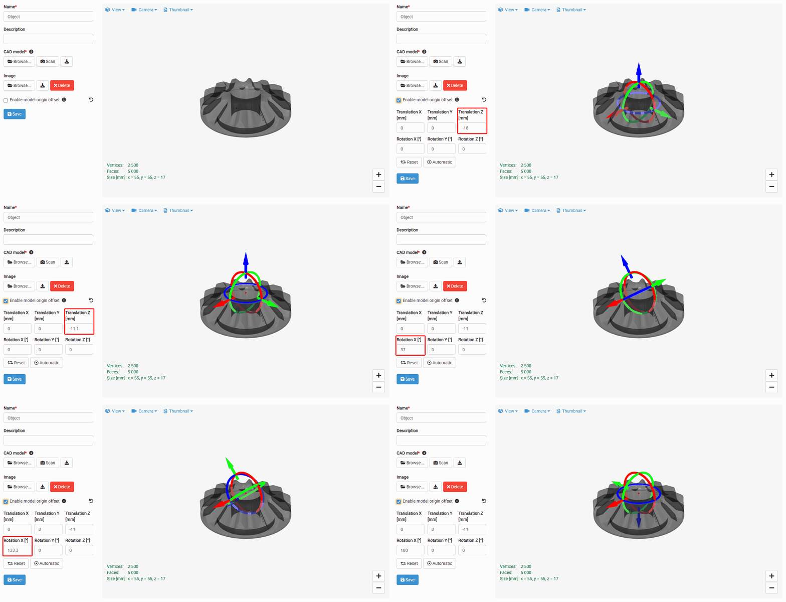
Moving the origin of the cogwheel example: the origin from the STL file, Automatic, then Translation Z −11 mm and Rotation X 180°, so the origin is in the middle of the top face with the Z-axis pointing down. The model is shown semi-transparent here so that the marker inside it is visible.
In Bin Picking Studio, use Origin transformation in the mesh tools instead.