Integration Guide Kassow Robots LS
Note: It is strongly recommended to read the Robot communication overview prior to this integration guide.
Note 2: It is strongly recommended to use the latest version of the integration guide included in the latest available version of the robot module. To download the robot module, please visit the official Photoneo website.
Contents
1 Prerequisites
The Photoneo Locator Studio module for Kassow Robots is delivered as a Capability Bundle (CBun) - a binary extension that is installed into the robot controller and adds the Locator Studio commands directly to the teach pendant program editor. This version of the LS interface was developed and verified on the FireFly.5 controller software package.
The following conditions must be met:
A Kassow Robots 7-axis robot with a Kassow Robots controller
Controller software package FireFly.5 or higher
A free Ethernet interface on the robot controller for the connection to the Photoneo Vision Controller
A USB stick (or network share) used to transfer the .cbun file and the example programs to the controller
A Photoneo Vision Controller running a Locator Studio server that supports the 1.5.0 communication protocol
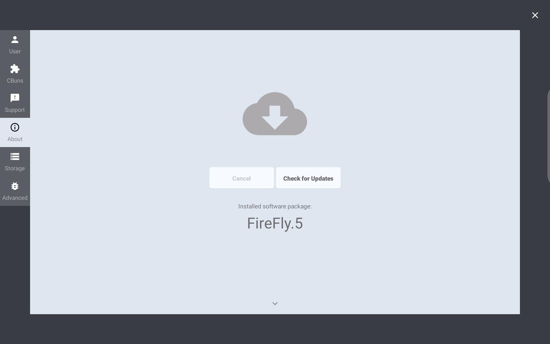
Note: The CBun handshake identifies itself to the Locator Studio server as KASSOW_ROBOTS/L/1.5.0XXX. The vision controller grants the matching protocol feature set based on this string, so a Locator Studio server supporting the 1.5.0 protocol is required.
General information on CBuns - how they are managed from the teach pendant, the basic interfaces and control items - can be found in the Kassow Robots Software Manual.
The Photoneo Locator Studio delivery consists of a single CBun file and a set of example robot programs:
2 Robot Controller Setup
2.1 Network configuration
The Locator Studio CBun opens a TCP client connection from the robot controller to the Action Request Server running on the Photoneo Vision Controller (default port 11003). Both devices must therefore be reachable on the same subnet.
The addressing used throughout this guide is:
Vision Controller IPv4 address: 192.168.1.1 / 24
Robot Controller IPv4 address: 192.168.1.2 / 24

NOTE: Subnet Mask 255.255.255.0 equals a 24 bit subnet mask representation. See this table for more combinations.
2.2 Copying the CBun and example programs to the controller
The Robot module files are transferred to the robot controller with a USB stick. Copy the delivered folder structure to the root of the stick and insert it into the USB port of the teach pendant. The file browsers used later in this guide expect the following layout:
usb0/untitled -> Kassow -> LS -> CBun -> photoneo_locator_studio.cbunusb0/untitled -> Kassow -> LS -> Example Programs -> *.kr2Note: The CBun file has to be installed only once per controller. The example programs are loaded individually from the Program -> Open dialog and are stored in the controller program storage after the first save.
2.3 Installing the Photoneo Locator Studio CBun

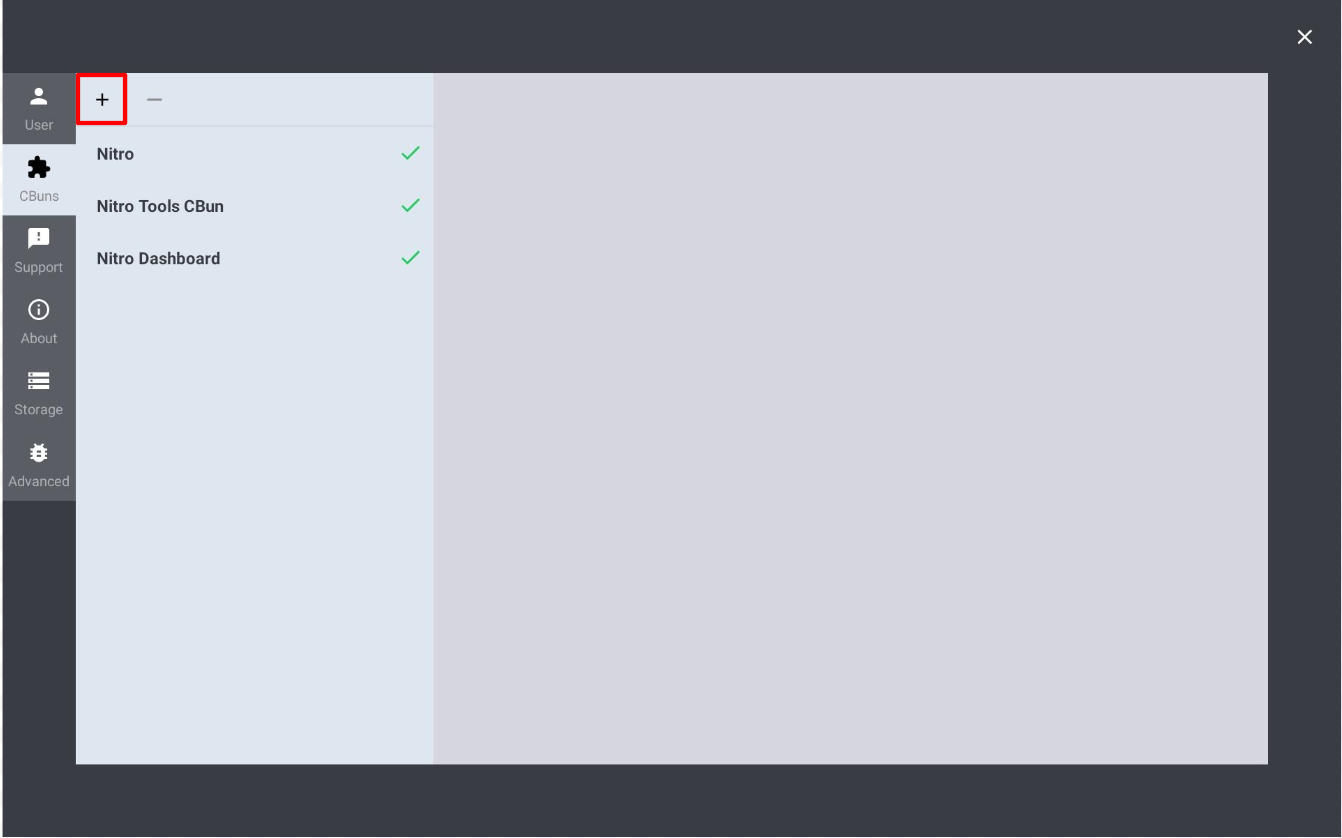

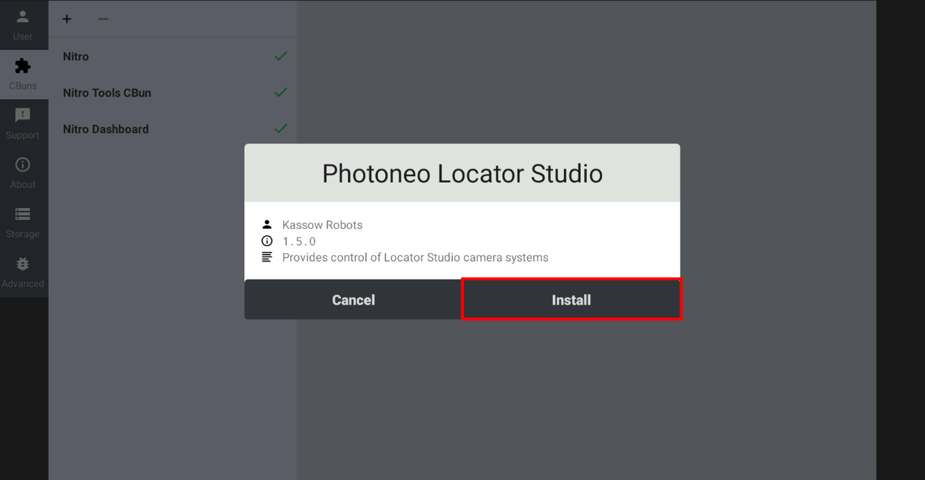
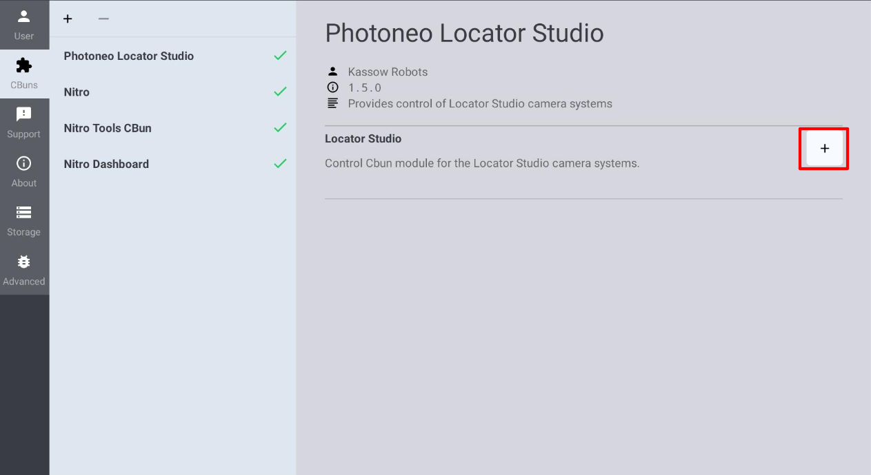
2.4 Configuring and activating the Locator Studio device
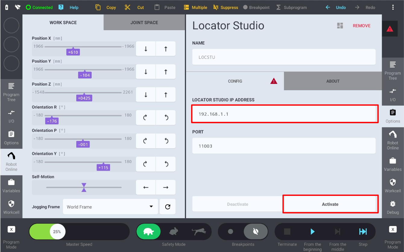
Adding the device opens its configuration page. The NAME field holds the instance name; the default LOCSTU is the prefix that will be shown for every Locator Studio command in the program tree. On the CONFIG tab, enter the connection parameters:
LOCATOR STUDIO IP ADDRESS - the IPv4 address of the Photoneo Vision Controller (192.168.1.1 in this guide)
PORT - the Action Request Server port, 11003 by default
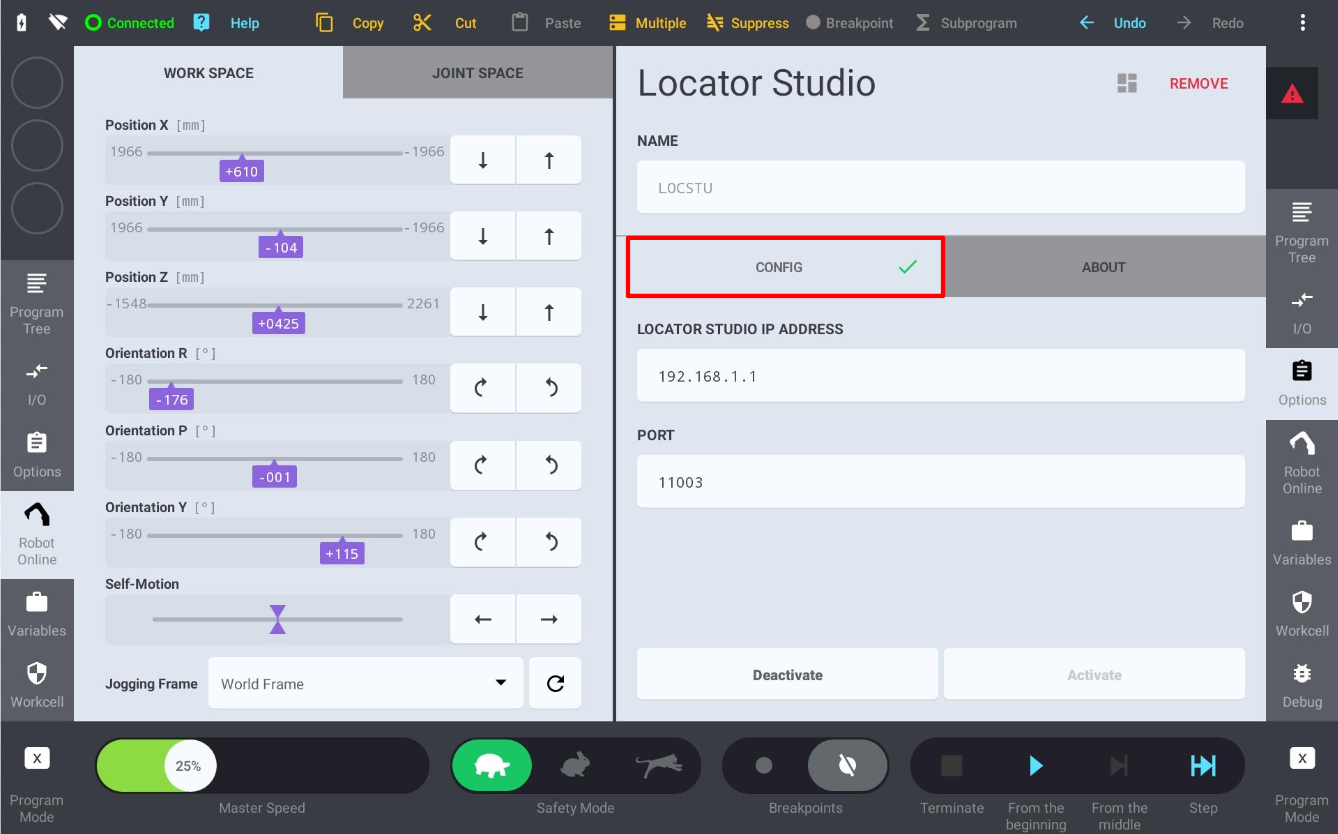
Note: The device configuration is part of the Workcell, not of the program. Remember to save the Workcell (Menu -> Workcell -> Save) after adding or reconfiguring the Locator Studio device.
2.5 Tool (TCP) and payload setup
For Locator Studio, tool setup is more important than for Bin Picking Studio, which is designed to operate with a zeroed tool and compensate for the offset programmatically. The general rule of thumb for Locator Studio is that all scanning and calibration must be done with a zero tool frame, while all picking must be performed with the real tool. For the purpose of this tutorial the example programs use a TCP pose variable named tcp_init with a Z offset of 300 mm. Before running the robot programs it is therefore necessary to configure tcp_init to match the physical construction of the gripper. Ideally this step should be performed before touching up the robot poses.
The example programs set the tool and the payload in the first two instructions of Sequence 1:
SET TCP = tcp_init
SET LOAD2 = load_init
tcp_init variable in the variable bar at the bottom of the screen to edit the tool frame: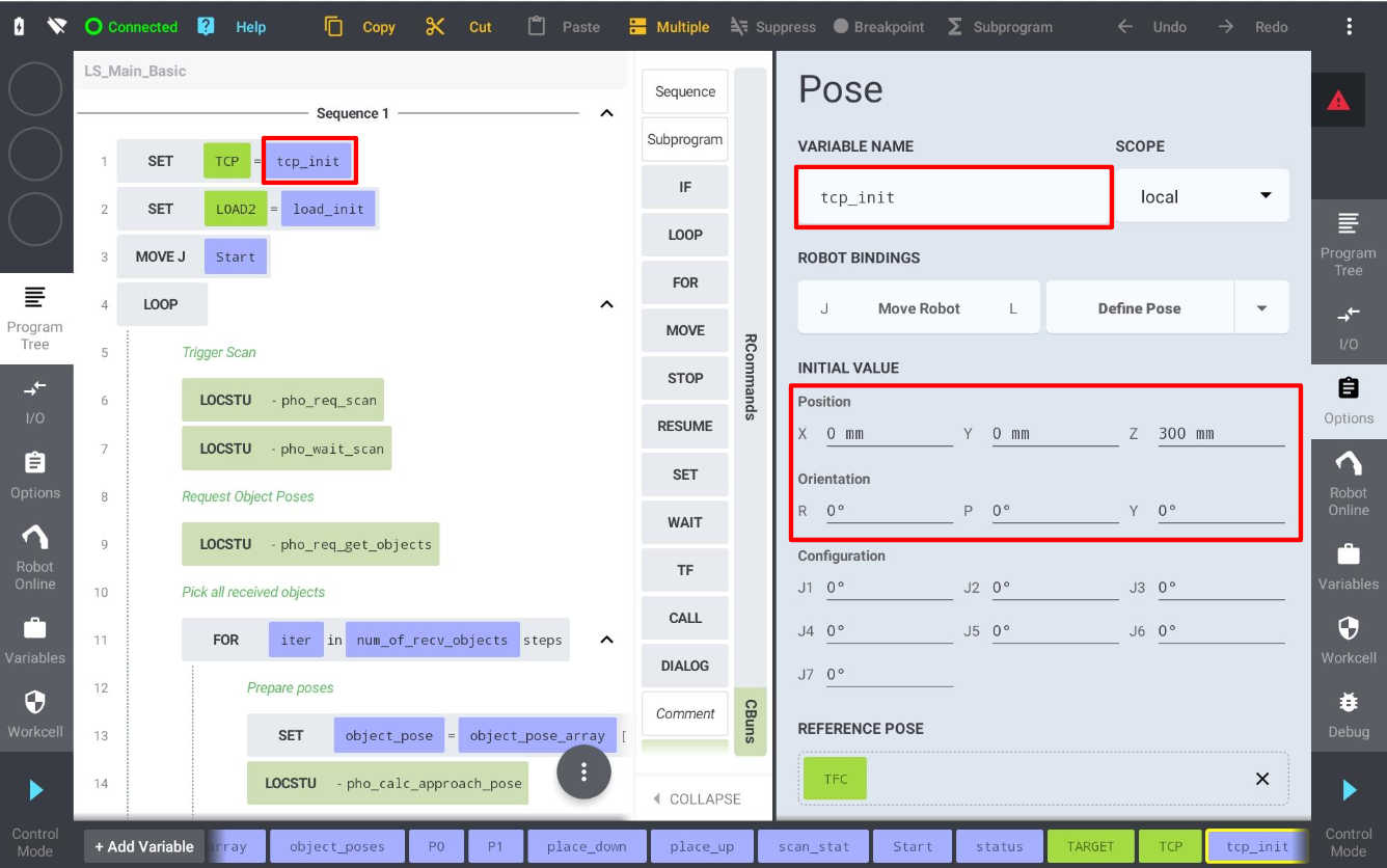
load_init to enter the mass, centre of gravity and inertia of the gripper: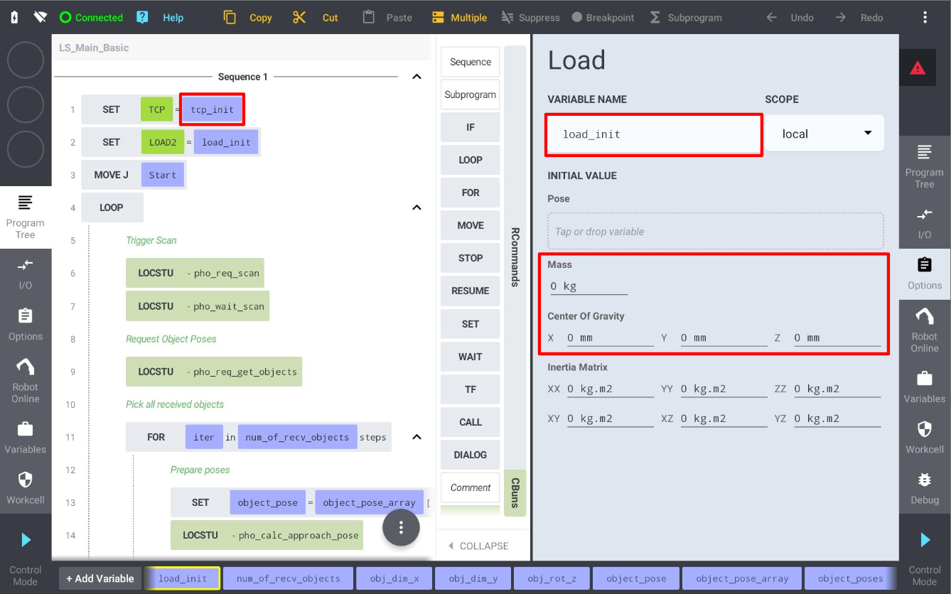
Note: pho_calib_add always reads the current flange-centre pose (flange to world) and is therefore independent of the configured TCP. Hand-eye scan requests are handled the same way, so no tool switching is required around the vision requests themselves - but the picking motions must use the real tool frame.
3 Robot Module
Note: It is strongly recommended to read the Photoneo robotic API prior to this section (login: customer / password: Ready2LearnHow2Pick).
3.1 Connection to the Photoneo Vision Controller
The connection to the Action Request Server running on the Vision Controller side is opened by the CBun itself when the Locator Studio device is activated - either manually from the device CONFIG page (section 2.4) or automatically when the workcell is loaded. Change the LOCATOR STUDIO IP ADDRESS field to match the IP address of the Vision Controller you are connecting to; in case of this tutorial it is 192.168.1.1.

On the robot side, the connection state is indicated by the green check mark on the CONFIG tab of the Locator Studio device. The link can also be verified from the program at any time with the pho_req_comm_check command, which returns response code 0 when the connection is alive - see the LS_Main_Basic_Comm_Check example program.
3.2 Request List
This section describes the available API calls provided by the Robot module. These commands are inserted into the program tree from the CBuns tab of the command palette and are intended for high-level control of the locator application.
Note: Please read Action requests for detailed documentation of the underlying communication protocol.
Note: The ID column lists the request code sent over the Photoneo communication protocol. pho_calc_approach_pose is a purely local geometric helper and sends no request to the vision system.
Request |
ID |
CBun command |
Input |
Populates |
|---|---|---|---|---|
Calibration Start |
25 |
|
Solution Id
Vision System Id
|
Response Code |
Calibration Add Point |
5 |
|
None (current flange pose is read automatically) |
Response Code |
Calibration Save |
27 |
|
None |
Calibration Accuracy
Calibration Matrix (RobotPose)
Response Code
|
Calibration Stop |
26 |
|
None |
Response Code |
Scan (blocking) |
19 |
|
Vision System Id
Scan Type (Extrinsic / Hand-eye)
|
Response Code |
Scan Start (non-blocking) |
19 |
|
Vision System Id
Scan Type (Extrinsic / Hand-eye)
|
— |
Wait for Scan |
19 |
|
None |
Response Code |
Trigger Scan (MultiView) |
30 |
|
Vision System Id
Scan Type (Extrinsic / Hand-eye)
|
Response Code |
Reuse Scan |
31 |
|
Vision System Id
Scan Type (Extrinsic / Hand-eye)
|
Response Code |
Get Single Object |
20 |
|
Vision System Id
Pose Mask
|
Detected Object Pose
Response Code
Solution based Info Data: Tool Invariance, Gripping Point Id, Gripping Point Invariance, Object Dimension X / Y, Object Rotation Z, NN Label, Max Z Height, Tilt
|
Get Objects |
20 |
|
Vision System Id
Requested Object Count (0 = all)
|
Object Poses Array
Returned Object Count
Response Code
|
Get Vision System Status |
22 |
|
Vision System Id |
Localized Object Count
Number Of Ready
Processing State
Response Code
|
Change Solution |
9 |
|
Solution Id |
Response Code |
Start Solution |
10 |
|
Solution Id |
Response Code |
Stop Solution |
11 |
|
None |
Response Code |
Get Running Solution |
12 |
|
None |
Solution Id
Response Code
|
Get Available Solutions |
13 |
|
None |
Solution Id Array
Response Code
|
Change Bounding Box |
33 |
|
Vision System Id
Bounding Box Id
|
Response Code |
Comm Check |
100 |
|
None |
Response Code |
Calculate Approach Pose |
local |
|
Target Pose
Reference Frame (World / Tool)
Axis (X / Y / Z)
Offset [mm]
|
Approach Pose
Response Code
|
Note: pho_req_scan_full performs the scan and waits for the result in a single step. pho_req_scan and pho_wait_scan split the same request into a non-blocking start and a blocking result read, so the robot can move while the vision controller is processing. All three use request code 19.
Note: Per-object Info Data is returned only by pho_req_get_single_object, as optional scalar Number out-parameters. Wire up only the fields you need; items that are not populated by the active solution type are returned as 0. The values are raw (integer / fixed-point) - the robot program applies any required scaling.
Every request also exposes an optional Response Code output. Binding it to a program variable suppresses the error pop-up window and leaves error handling to the program - see section 4.2 for how to bind it in practice. Error codes together with their description and troubleshooting can be found here.
3.3 Value functions
In addition to the program commands listed above, the CBun provides value functions that can be used directly inside expressions - for example in an IF or LOOP condition - without inserting a separate program step:
Function |
Input |
Returns |
|---|---|---|
|
Vision System Id, Pose Mask |
RobotPose - next localized object pose |
|
Vision System Id |
Number - count of localized objects awaiting processing |
|
Vision System Id |
Number - total count of detected objects, including rejected ones |
|
Vision System Id |
Number - 0 when processing is complete, 1 while recognition is running |
|
None |
Number - ID of the currently deployed solution |
3.4 Example Programs
Several example programs are delivered with the Photoneo Kassow module. They demonstrate how to properly use the requests listed in section 3.2 for various use cases:
Example program |
Description |
|---|---|
LS_Main_Basic
LS_Main_Basic_Hand_Eye
|
These simple examples demonstrate the basic workflow: connect to a vision controller, send a scan request, request object poses, receive object poses and execute picks for both statically and hand-eye mounted sensors. The scan is split into The examples also illustrate error handling - each command writes its result into the |
LS_Main_Basic_Single_Object |
Same as LS_Main_Basic but demonstrates fetching a single object at a time with |
LS_Calibration
LS_Calibration_Hand_Eye
|
Calibration examples for statically mounted and hand-eye mounted sensors. Requirements: initial calibration of the Vision System must be started and confirmed manually by the user on the Locator Studio side. Calibration steps: teach all 9 calibration poses (P1 - P9). Points can be added to the calibration table manually by clicking “Add Calibration Point” on the Locator Studio side, or by calling Calibration accuracy: the general rule is that the calibration error should remain below 3 mm. Higher errors typically indicate a systematic issue in the calibration setup. Automatic recalibration (optional): once the first calibration is successful and automatic recalibration is enabled in the Vision System settings, use Important: the calibration object - either a ball or a marker pattern - must remain in its original position to ensure successful automatic recalibration. |
LS_Main_Basic_Multi_VS |
Same as LS_Main_Basic, but with switching between two Vision Systems. The Vision System Id parameter of every request is essential in this setup - it determines which Vision System is triggered or queried. |
LS_Main_Basic_Change_Sol |
Same as LS_Main_Basic but with all solution-switching related requests. It highlights how to activate different solutions using |
LS_Main_Basic_Change_BBox |
Same as LS_Main_Basic but demonstrates switching the active localization bounding box at runtime with |
LS_Main_Basic_Comm_Check |
Same as LS_Main_Basic, but the program verifies the link to the vision controller with |
LS_Main_Basic_Multiview_Static |
Static MultiView (meshing) example. This process shows stitching of multiple scans before initiating localization, which is particularly useful for complex scenes or large objects. It employs a static approach, where the robot stops at each scanning position to trigger and capture a scan. Procedure: move through all scanning poses ( Scan limit: keep the total number of scans below 10 to ensure optimal system performance. |
LS_Main_Basic_Multiview_Dynamic |
Dynamic MultiView example. This setup demonstrates integration of Photoneo Instant Meshing technology. It leverages the MotionCam-3D Parallel structured light technique to capture multiple scans while the robot is in motion, allowing for rapid accumulation of 3D data into a single point cloud. The implementation uses a second program sequence (Sequence 2) running in parallel with the motion sequence. The motion sequence sets the Requirements: MotionCam-3D is required for Instant Meshing technology (standard PhoXi 3D Scanners do not support dynamic scanning). In the LS Solution, Trajectory control: ensure the scanning trajectory is smooth and keeps the bin within the scanner field of view to prevent tracking loss. |
LS_Main_Basic_Reuse_Scan |
Same as the LS_Main_Basic_Multi_VS example but introduces Procedure: perform a regular scan for VS1 to capture the scene, then use |
4 Runtime
Once the solution is fully configured on the Vision Controller side, it is time to finalize the remaining steps on the robot side and proceed to executing the LS_Main_Basic program.
4.1 Loading an example program
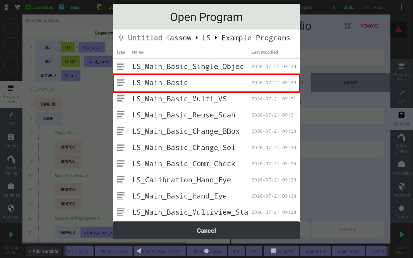
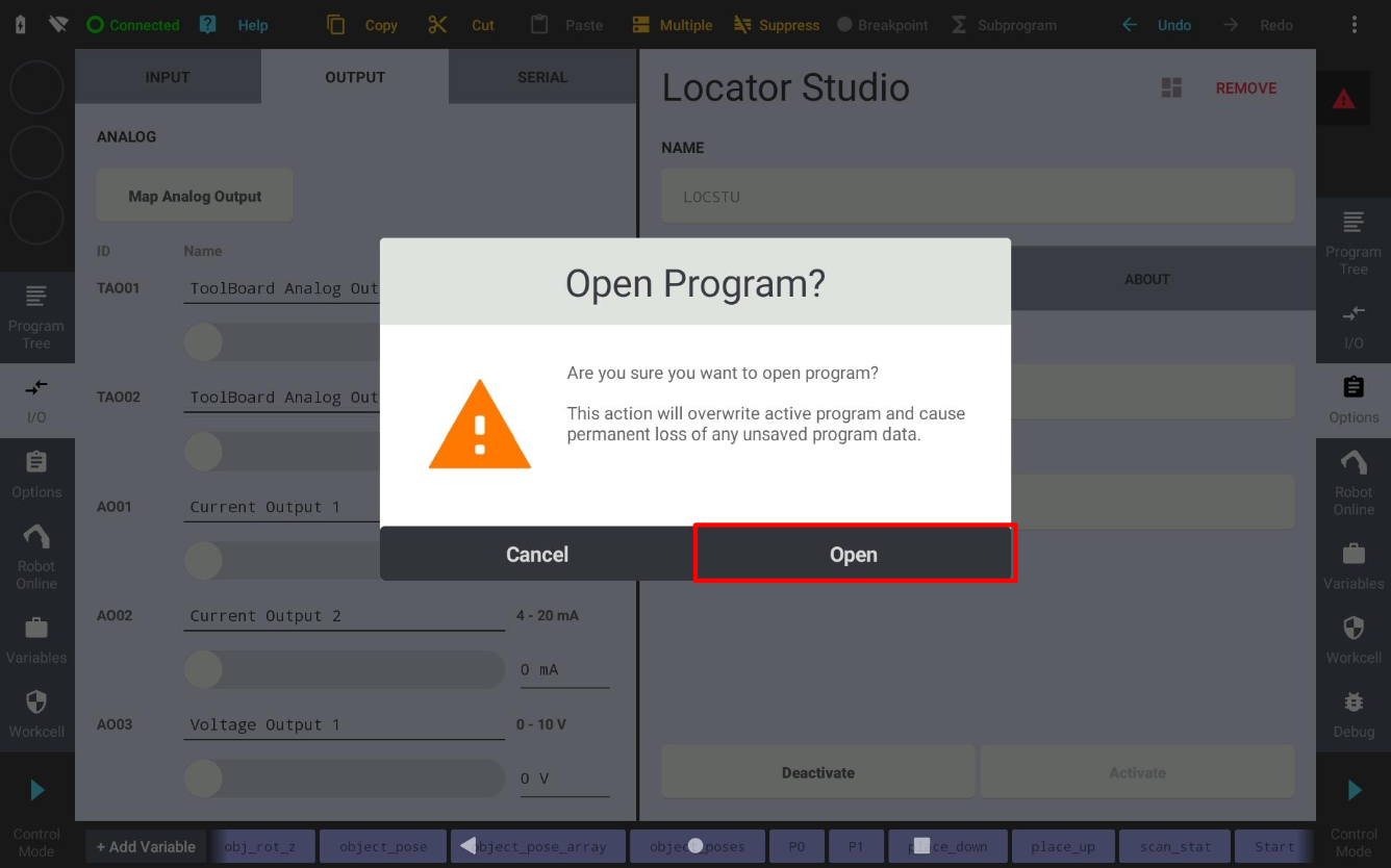
4.2 Program structure
All main example programs follow the same structure. Using LS_Main_Basic as the reference:
SET TCP = tcp_init and SET LOAD2 = load_init - set the tool frame and the payload (see section 2.5)
MOVE J Start - move to the start pose above the bin
LOOP - the endless Pick and Place loop
Trigger Scan - LOCSTU
pho_req_scanfollowed by LOCSTUpho_wait_scanRequest Object Poses - LOCSTU
pho_req_get_objectsfillsobject_pose_arrayandnum_of_recv_objectsPick all received objects - a FOR loop over
num_of_recv_objectsstepsPrepare poses -
object_pose = object_pose_array[iter,0]and LOCSTUpho_calc_approach_poseApproach Object - MOVE L
approach_pose, MOVE Lobject_poseGripper Command -
SET DO1 = 1, WAITDeapproach - MOVE L
approach_posePlacing - MOVE J
place_up, MOVE Lplace_down,SET DO1 = 0, WAIT, MOVE Lplace_up
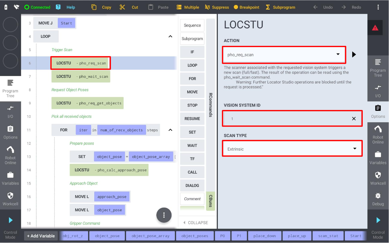
pho_req_get_objects fetches all localized poses in a single request. Set Requested Object Count to 0 to fetch every available object, and bind Object Poses Array and Returned Object Count to the program variables that will be used by the picking loop: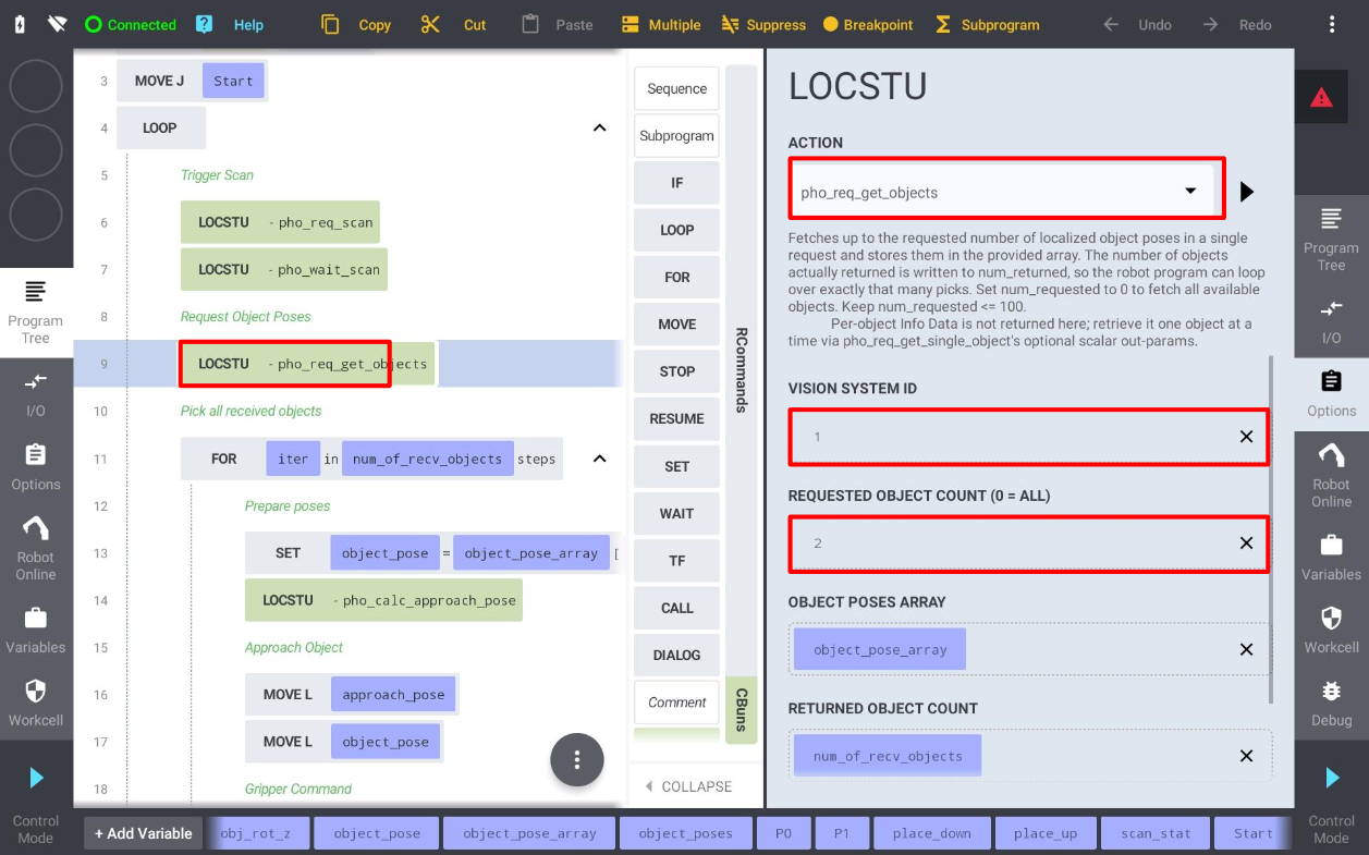
status variable. Every request exposes this optional output and it should be checked by the program: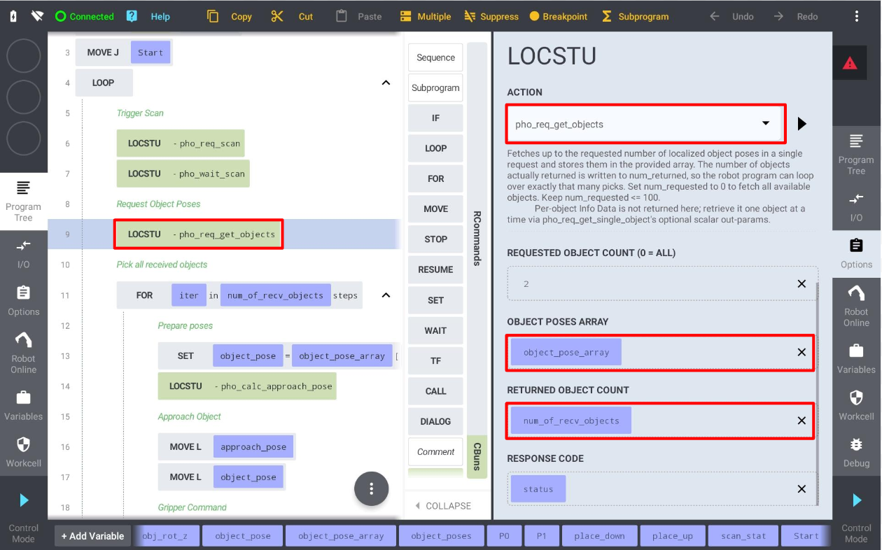
pho_calc_approach_pose derives the approach pose from the received object pose. With Reference Frame set to Tool and Axis set to Z, a positive Offset moves the approach pose back along the object’s own Z axis - a stand-off away from the object - while keeping the object orientation: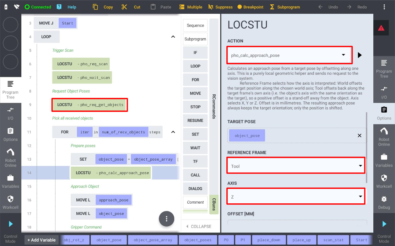
4.3 Gripper commands
SET DO or other I/O related commands to control the gripper actions in the grasp and drop points. In the example programs the gripper is actuated with SET DO1 = 1 after reaching the object pose and SET DO1 = 0 at the placing position, each followed by a WAIT instruction:
4.4 Teach Positions
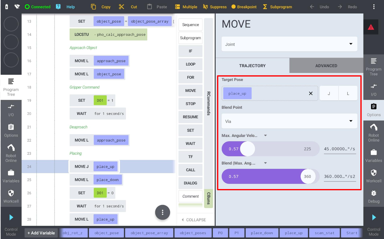
After opening LS_Main_Basic or another template, there are a couple of poses that need to be touched up before running the program:
Start - usually touched up above the centre of the bin or of the scanning area, in a position where the robot is out of the field of view of the scanner.
place_up / place_down - the placing position; place_down is the drop point and place_up is the retract pose above it.
scan_pose_1 … scan_pose_3 - the additional scanning waypoints used by the MultiView examples.
Calib_Start, P1 … P9 - the calibration start pose and the nine calibration poses used by the calibration programs.
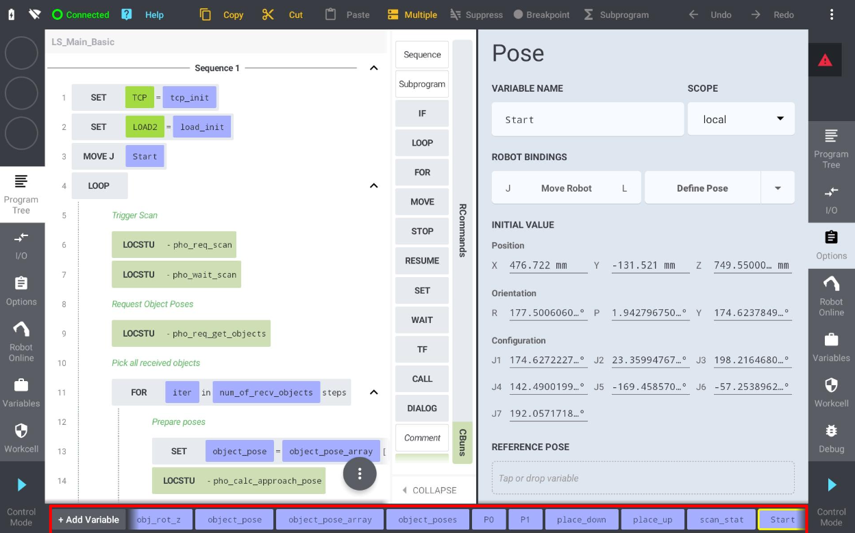
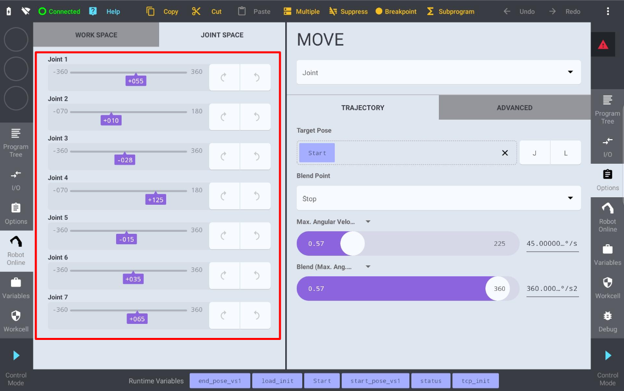
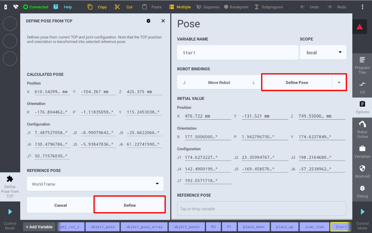
Note: Kassow robots have 7 joints, so a Cartesian pose does not uniquely define the arm posture. The joint configuration stored with the pose (J1 - J7) resolves the redundancy, which is why poses should always be taught by jogging the real robot rather than by typing in coordinates.
4.5 Calibration
There are 3 methods of calibration available in Locator Studio:
Sphere based calibration - for statically mounted sensors
Marker pattern based calibration - for carried or hand-eye mounted sensors
Marker pattern based calibration - for static sensors and user / work object calibration
For the first two methods it is required to capture a calibration object from 9 poses with sufficient variance in tool pose data. It is always recommended to calibrate with a zero tool frame and in the world frame; using non-zero frames may result in skewed calibration results.
For the third method, a single scan is enough. The main difference with respect to the first two methods is that the origin of the scene is not identified with the robot origin but is located in the marker pattern origin. The third calibration method cannot be automated and must be performed manually.
The first two calibration procedures can also be done directly without using the Kassow module calibration programs. This can be achieved by starting the calibration on the LS side, jogging the robot from point to point and manually adding the points on the LS side. However, for production setups where recalibration is expected, it is recommended to record the calibration points into the program and to ensure that the transition between these poses is collision free.
The Kassow module provides two programs for the automated calibration process:
LS_Calibration - calibration procedure for a statically mounted sensor (sphere based calibration).
LS_Calibration_Hand_Eye - the same procedure for a carried, hand-eye mounted sensor (marker pattern based calibration).
Both programs move the robot through the taught poses P1 - P9, call pho_calib_add in each of them and finish with pho_calib_save and pho_calib_stop. They therefore enable automatic recalibration without touching the LS system at all.
In general the calibration error should be below 3 mm. Use the verification tab to check if the point cloud overlay over the robot body or gripper matches perfectly. Any discrepancy needs to be investigated because it can lead to a collision. The most common issues are: wrong tool frame values, incorrect gripper model orientation, incorrect robot model selection, encoder zeroing and a flimsy robot base.
4.6 Prerequisites
Final pre-deployment check before running the Locator Studio interface from the robot side. Make sure that:
The Locator Studio solution is properly configured on the Vision Controller side
The network setup on the robot side is completed and the Locator Studio device is activated
All Vision Systems defined in the solution are calibrated
The tool frame (
tcp_init) and the payload (load_init) match the physical gripperAll local poses in the main program have been touched up properly
Gripper procedures are prepared and working
4.7 Running the LS_Main_Basic program

NOTE: It is strongly recommended to decrease the Master Speed to a low value - for example 25% - before running the program for the first time. The Master Speed slider is located in the lower left corner of the teach pendant in Program Mode.
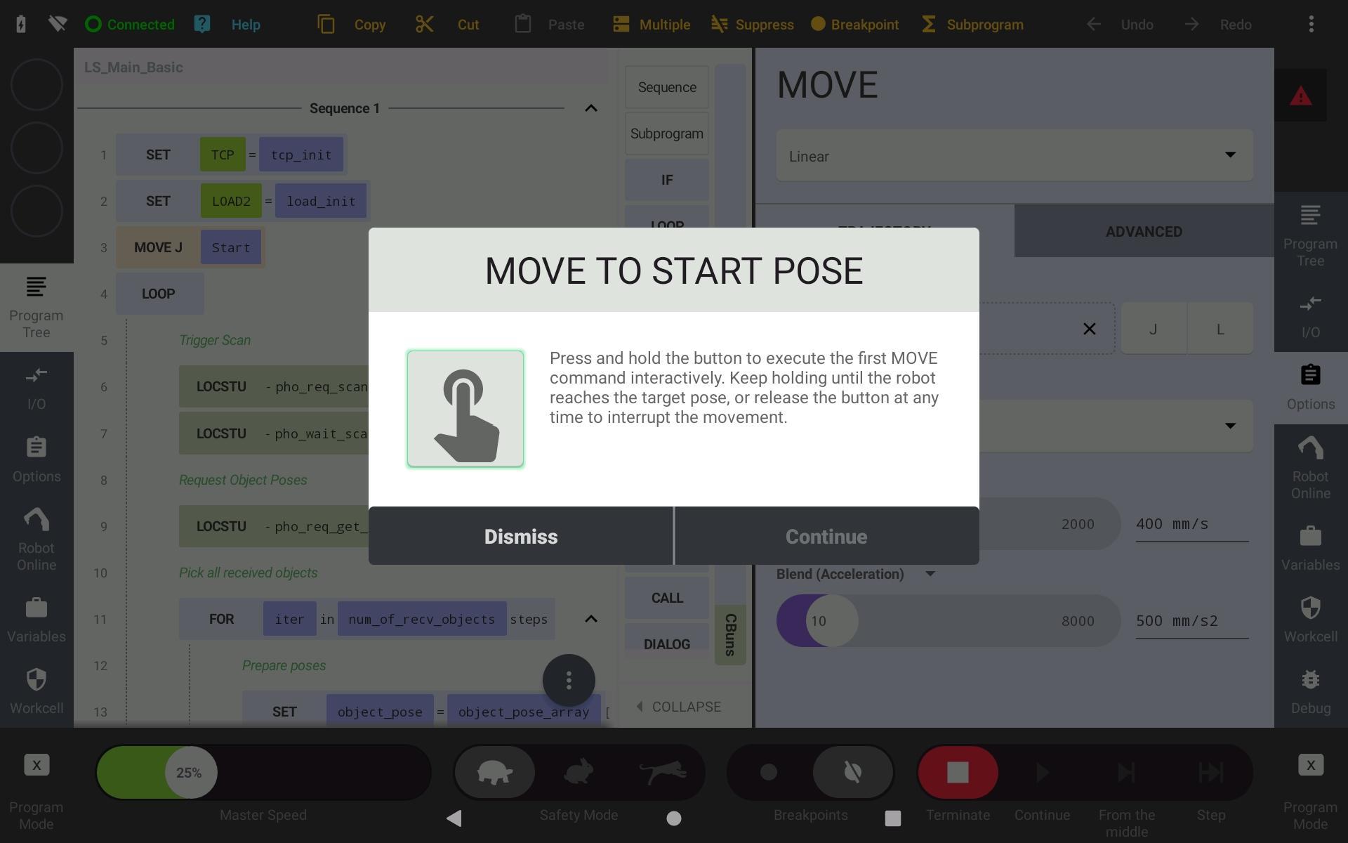
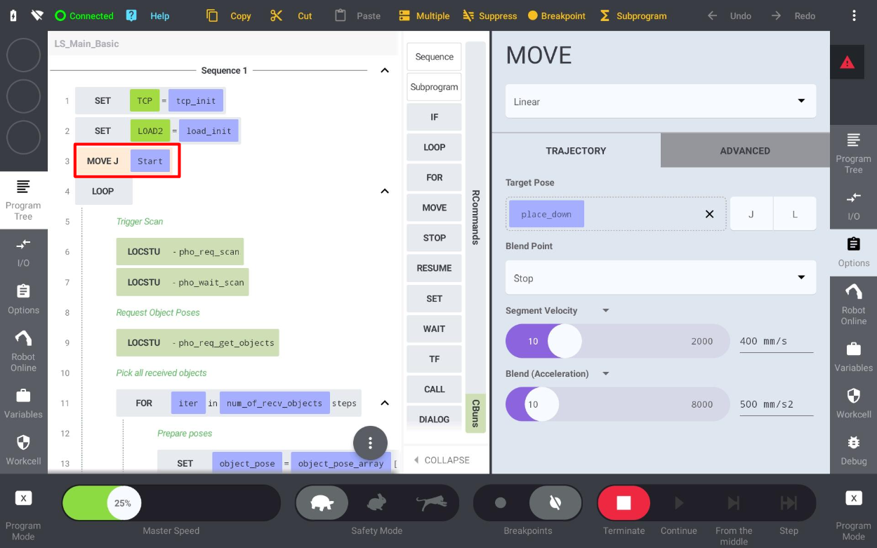
If there is a pickable object in the scene and the Cartesian pose for this object has been received by the robot controller, the robot starts moving towards the first object.
If everything looks fine, keep moving the robot towards the first target and check that the path is correct. At this point, if the robot is too far from the object or pushes the object too deep, then make modifications to the object origin or to the tcp_init tool frame.
If the robot movement looks fine, set up your own placing routine and slowly ramp the Master Speed back up to 100%.
Congratulations, you have successfully deployed the Photoneo Kassow Robots Locator Studio interface. You can now focus on improving your application further. Use the Cheat Sheet and the example programs as your guidelines.