CAD Localization
The CAD localization engine finds objects in the point cloud by matching them with the 3D (CAD) model of the picked object. This page gives an overview of the engine and links to the pages that describe its parts. It applies to both Bin Picking Studio (BPS) and Locator Studio (LS).
Where it is used
Software module: CAD Localization (“Enables the CAD-based localization engine”). See Software modules.
Solution types: CAD Localization (LS) and CAD Picking (BPS). See Solution types.
What you need
A 3D model of the object. CAD solutions have a Picked object step, where you upload or scan the model and prepare it. See Mesh tools.
A vision system with a 3D sensor and a scanning profile. See 3D sensors and scanning profiles.
A localization profile. It is set on the Localization tab of the vision system. The CAD localization profile stores a pre-trained model for the specific CAD geometry, so it can be large. Since BPS 1.11 its size is optimized, and older profiles are migrated automatically.
How it works
The engine looks for the object in the point cloud of the scan in these steps:
Segmentation – the scene is split into segments. Each segment is a continuous area of the scan. Segments that are too small (noise) or too large (for example the bin floor) are left out.
Searching – the engine looks for places where points of the model match points of the scene. Each match is a candidate pose of the object.
Fine alignment – each candidate pose is refined with the ICP (iterative closest point) algorithm, so the model fits the scene as closely as possible.
Checks – a candidate is accepted only if enough of it matches the scene (Overlap) and, if set, it passes the occlusion and model feature checks.
The engine stops when one of the stop criteria is met: a time limit, a number of found objects, or a time without finding a new object.
The found pose is the pose of the model’s coordinate system. If the object is symmetrical, the pose can be turned around the axis of symmetry at random. To fix this for objects that are almost symmetrical, use model features and feature alignment.
Localization profile
The localization profile is a .plcf file. It holds the model of the object and all localization settings. Each vision system has its own profile, on the Localization tab of the vision system.
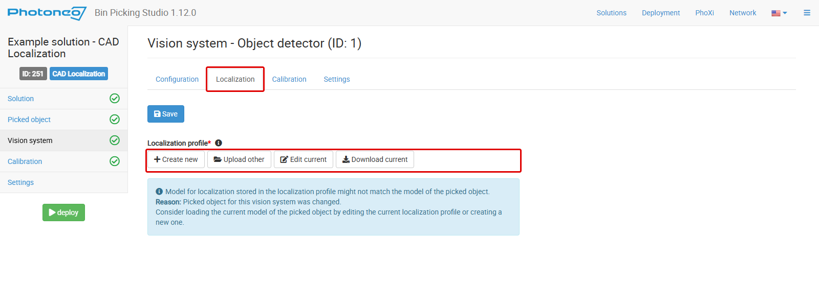
The Localization tab of the vision system in the CAD Localization example solution. Red frames: the tab and the Localization profile buttons.
The buttons are:
Create new – opens the localization profile editor with a new profile.
Upload other – uploads an existing
.plcffile. The Studio warns if the file is larger than the recommended size (1 GB), because a large file can slow down the bin picking.Edit current – opens the localization profile editor with the current profile.
Download current – downloads the current profile as a
.plcffile.
If you change the picked object of the vision system, the tab shows a notice: the model stored in the profile might not match the model of the picked object. To use the new model, edit the current profile or create a new one.
Localization profile editor
Create new and Edit current open the localization profile editor. While it is open, the top bar of the Studio shows Localization running with the name of the vision system. Nothing is saved until you click Save configuration.
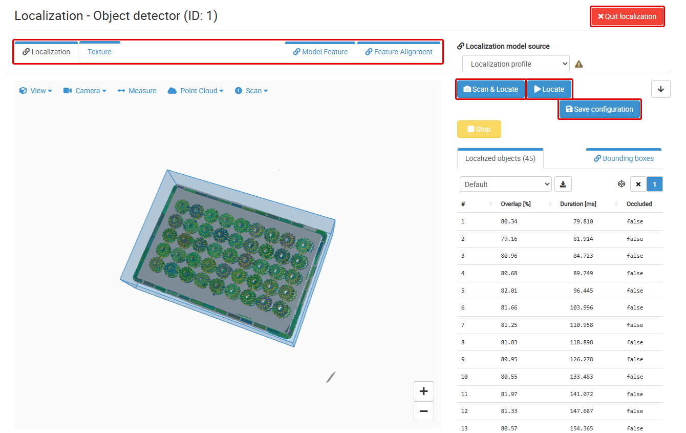
The localization profile editor after Scan & Locate on the example scan: 45 objects found. Red frames: the editor tabs, Scan & Locate, Locate, Save configuration and Quit localization.
The parts of the editor:
Tabs
Localization – the 3D visualizer and the localization settings.
Texture – the texture (2D image) of the scan.
Model Feature and Feature Alignment – see CAD Model Detail.
Localization model source – which model the engine uses: the model stored in the Localization profile, or the model of the Picked object. A warning sign next to it shows that the two models might not match.
Scan & Locate – takes a new scan and runs the localization on it.
Locate – runs the localization again on the current scan. Use it to test changed settings on the same scene.
Save configuration – saves the settings into the localization profile. Test the changed settings with Locate or Scan & Locate first.
Stop – stops a running localization.
Quit localization – closes the editor. If there are unsaved changes, the Studio asks you to confirm.
Localized objects – a table of the found objects with their Overlap [%], Duration [ms] (the time from the start of the localization until the object was found) and Occluded. The list above the table switches the columns: Default, Searching, Fine alignment, Occlusion handling, Model feature alignment and Overview.
Bounding boxes – the regions of interest for the localization. See Bounding boxes.
Below the visualizer are the Stop criteria and the Localization settings. Each setting has an info icon with a short help text and a reset icon that sets it back to its default value. Values that differ from the default are highlighted. Reset to defaults resets all localization settings.
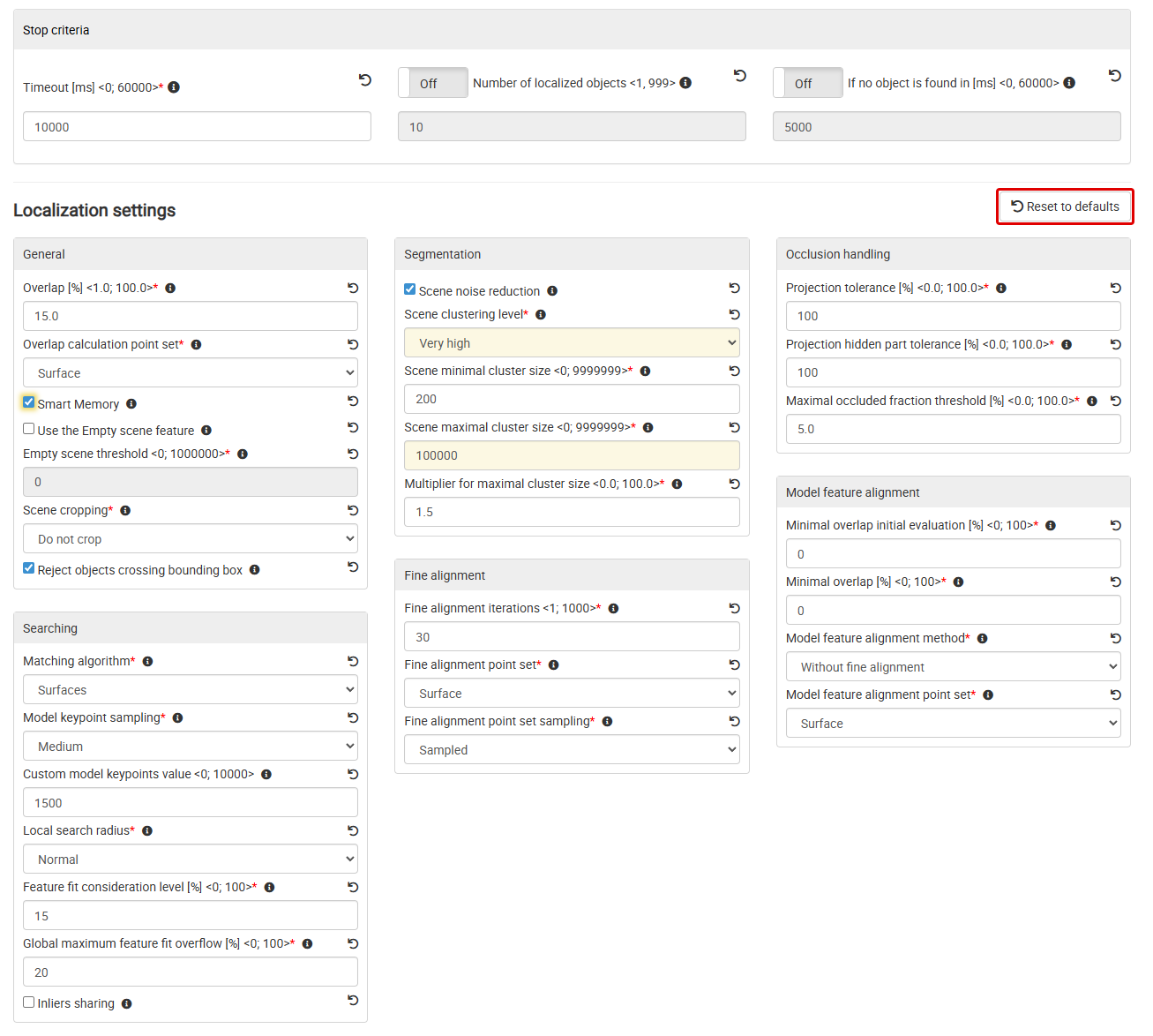
The Stop criteria and Localization settings of the CAD Localization example solution. Reset to defaults is framed in red. The highlighted values (Scene clustering level, Scene maximal cluster size) differ from the defaults.
Localization settings
The ranges and default values below are the ones shown in Bin Picking Studio 1.12.
Stop criteria
The localization stops as soon as one of the enabled criteria is met. Always keep a time limit, so the search can’t run too long.
- Timeout [ms] (0–60000, default 10000)
The localization stops when this time runs out.
- Number of localized objects (1–999, default Off)
The localization stops when it has found this number of objects.
- If no object is found in [ms] (0–60000, default Off)
The localization stops when it finds no new object for this time. The timer starts again after each found object. Useful when the number of objects in the scene changes a lot.
General
- Overlap [%] (1–100, default 15)
How much of the object must match the scene for a candidate to be accepted. The overlap compares the number of scene points that match the model with the number of model points that the sensor could see from its position. So 100 % means “the sensor sees everything it can see of the object in this pose”. A higher overlap gives fewer wrong results, but can also reject correct ones and makes the localization slower.
To find a good value, start low (for example 20 %), check the results on several scenes and raise the value until the wrong results are gone.
- Overlap calculation point set (default Surface)
Which points are used to compute the overlap:
Surface – for models without clear edges (mostly rounded surfaces).
Edges – for models with clear edges.
- Smart Memory (default Off)
Loads the results of the previous localization run again. This speeds up the next runs when the scene changes only a little between them. During deployment it is set by the Do not force Smart Memory vision system setting. See Processing (CAD Picking) and Advanced settings (CAD Localization).
- Use the Empty scene feature (default Off)
When enabled, the localization stops early with Empty scene when the number of valid 3D points is below the Empty scene threshold. The robot then gets the Empty scene error in response to a request for a trajectory or an object pose. You can check the number of valid points in the Scan menu of the 3D visualizer.
For CAD localization the number of valid points is counted on a subsampled point cloud. It also depends on the bounding box (only points inside it count), on Scene cropping, on the segmentation settings and on Model keypoint sampling.
- Empty scene threshold (0–1000000, default 0)
The number of valid 3D points below which the scene counts as empty.
- Scene cropping (default Do not crop)
How the point cloud is cropped by the bounding box. Has no effect when no bounding box is enabled.
Do not crop – segmentation and the other steps run on the whole point cloud. Collisions are checked with the whole point cloud.
Into Bounding Box for Localization – segmentation and the other steps run only inside the bounding box, which can make the localization faster. Collisions are still checked with the whole point cloud.
Into Bounding Box for Localization and collision checking – as above, and collisions are checked only with the points inside the bounding box. For MultiView only.
- Reject objects crossing bounding box (default On)
When enabled, objects outside the bounding box and objects partly inside it are rejected. When disabled, objects partly inside the bounding box can be accepted.
Searching
- Matching algorithm (default Surfaces)
Which points the engine matches between the model and the scene:
Surfaces – for objects with smoothly curved surfaces, like a ball or an oval.
Edges – for objects that are mostly defined by their edges.
Combined – for flat-sided objects with sharp (not rounded) edges, like a cube.
- Model keypoint sampling (default Medium)
How densely the model is sampled: Sparse, Medium, Dense or Custom. More points give more detail, but take longer to compute, mainly with the Surfaces algorithm. With Combined, Dense is not demanding and can give better results.
This setting also sets how far a scene point can be from the model and still count as a match when the overlap and the fine alignment are computed. Dense makes this distance smaller, Sparse makes it larger.
- Custom model keypoints value (0–10000, default 1500)
The number of model keypoints. Used only when Model keypoint sampling is Custom.
- Local search radius (default Normal)
The engine searches around many keypoints in the scene. This sets the radius of each search: Short, Normal or Medium. It can make the localization faster or slower, but it should not change much whether the object is found. A shorter radius helps when the object is large compared with the scan (when it covers almost the whole scene).
- Feature fit consideration level [%] (0–100, default 15)
How much of a segment must match the model for the segment to count as part of the object. The rest of the segment counts as overflow. Changing this value is not recommended.
- Global maximum feature fit overflow [%] (0–100, default 20)
How much of all segments can overflow the found object, as a percentage of the total size of the segments.
- Inliers sharing (default Off)
When disabled, points of one segment can belong to only one object. If more objects share a segment, only one of them is found. When enabled, all objects that share a segment can be found.
Segmentation
The engine first splits the scene into segments. In the visualizer each segment has its own shade of green. It does not matter if one object is split into several segments. But if several objects end up in one segment, adjust these settings.
- Scene noise reduction (default On)
Makes the segments more continuous. Keep it on. Turn it off only if Scene clustering level is Very high and the segmentation is still not good enough.
- Scene clustering level (default Normal)
Low, Normal, High or Very high. A higher level creates more segments. Choose a level that puts two separate objects into two different segments, but does not split one flat area of an object into many small segments.
- Scene minimal cluster size (0–9999999, default 200)
The smallest number of points in a segment. Smaller segments are left out. Ideally, noise is left out but all important parts of the scene are kept.
- Scene maximal cluster size (0–9999999, default 3500000)
The largest number of points in a segment. Larger segments are left out. Use it to remove large background segments. Segments that are much larger than the model are always left out.
- Multiplier for maximal cluster size (0–100, default 1.5)
Leaves out segments that are too large compared with the model. The limit is the diagonal of the model’s bounding box times this value. Raise it to let the engine use larger segments.
Fine alignment
Fine alignment refines each found pose with the ICP (iterative closest point) algorithm. The scene stays fixed and the model is moved and turned step by step until it fits the scene best.
- Fine alignment iterations (1–1000, default 30)
The number of ICP steps. The recommended range is 6–30. More steps can slow the localization down. Too few steps may not be enough to fit the model.
- Fine alignment point set (default Surface)
Surface – for models without clear edges (mostly rounded). Edges – for models with clear edges, for example flat or box-shaped objects.
- Fine alignment point set sampling (default Sampled)
Sampled – the default. Complete – uses all points. It is much slower, but in some cases more precise.
Occlusion handling
When the engine has found a pose, it can compute what the object should look like in the scan from that pose (a virtual point cloud of the model). Comparing this with the real scan removes wrong results. With the default of 100 % the check is turned off. Lower the values if you get wrong results.
- Projection tolerance [%] (0–100, default 100)
The largest share of the virtual points that can be closer to the camera than the real scanned points. With a correct pose this should not happen: the sensor would see the object, but it sees the points behind it. A lower value can help to find the correct orientation of the object.
- Projection hidden part tolerance [%] (0–100, default 100)
The largest share of the virtual points that can be further from the camera than the real scanned points. This can happen with a correct pose, but it means that something lies on top of the object. A lower value removes covered objects, so only the objects on top are kept.
- Maximal occluded fraction threshold [%] (0–100, default 5)
The largest share of the model’s surface that can be hidden (occluded) from the camera’s point of view.
Model feature alignment
These settings are used only when the object has model features and feature alignments: Minimal overlap initial evaluation [%], Minimal overlap [%], Model feature alignment method and Model feature alignment point set. See Model feature alignment settings.