Mesh Tools
The Mesh Tools panel lets you build or refine the 3D model of the object you want your robot to pick. You can bring in a model by uploading an existing file or by scanning the object directly from the web interface, and then clean it up using the built-in editing tools before saving it.
Contents
1 Creating a mesh model
You can provide a mesh model to Bin Picking Studio in two ways: by uploading a file you already have, or by scanning the physical object directly through the web interface.
1.1 Uploading a file
Bin Picking Studio accepts STL and PLY mesh files.
To upload a model:
Navigate to the Picked Object configuration page for the vision system you are setting up.
Click Upload model and select your STL or PLY file.
The model will appear in the 3D visualizer. Inspect it and proceed to the editing tools if any clean-up is needed.
1.2 Scanning directly from the sensor
If you have a physical sample of the object available and a 3D sensor connected to the vision controller, you can create a mesh model by scanning the object directly inside the web interface by selecting youe scanner ID.
Note: A model made from scan will be one-sided only, from the point of view of the scanner. It is best suited for objects that are either symmetrical or semi-oriented on the scene. For asymmetric objects in random orientations, a full 360° CAD model made either in CAD software or Photoneo 3D Meshing software is recommended.
To scan and import a model:
On the Picked Object page, click Scan from sensor.
Select the connected sensor from the list and click Trigger scan.
The scan is processed into a mesh and loaded into the visualizer automatically.
Use the editing tools described below to crop and clean the result before saving.
2 Editing the mesh
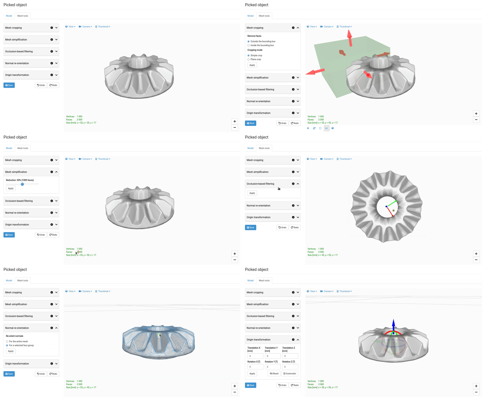
The Mesh Tools are located in a separate tab in the Picked Object page. The recommended order of operations is: crop first, then run any other filters as needed.
2.1 Cropping
Use cropping to remove parts of the mesh that do not belong to the object — for example, the table surface or bin walls that were included in the scan.
In the Mesh Tools panel, select Crop.
A bounding box appears in the visualizer around the mesh. Drag the handles to resize and reposition it so that it tightly encloses only the object you want to keep.
Choose whether to keep the geometry inside the box or remove it using the toggle below the visualizer.
Click Apply crop.
Tip: Crop before simplifying. Starting with a smaller mesh makes simplification faster and produces better results.
2.2 Simplification
Large or highly detailed meshes can slow down localization. Simplification reduces the number of triangles while preserving the overall shape of the object.
Select Simplify in the Mesh Tools panel.
Adjust the Target quality slider. A lower value removes more geometry; a higher value keeps more detail.
Click Apply.
If you oversimplify and the model geometry breaks, return to the previous version with the Undo button.
Note: Simplification may take up to a few minutes for large meshes.
2.3 Flipping normals
Triangles whose normals point inward (back-facing faces) can interfere with localization. If the mesh was imported or scanned with inverted normals — visible as a dark or inside-out appearance in the visualizer — you can correct this in one click.
Select Flip normals in the Mesh Tools panel.
Pick whether to invert the entire model, or only align individual backward-facing triangles based on a selected correctly oriented triangle.
Click Apply.
2.4 Occlusion filtering
Scanned meshes sometimes contain internal surfaces or hidden geometry that is not visible from the outside, or a one-sided model is desired when picking semi-oriented objects. Occlusion filtering removes triangles whose centre point is hidden behind other geometry.
Select Occlusion filter in the Mesh Tools panel.
Move the camera point of view so that the surface to be kept is visible.
Click Apply.
3 Adjusting coordinate origin
After all mesh editing is complete, you may want to adjust its origin point. The origin point is a reference for any symmetry, model feature or gripping point setup, so setting it to object center or corner will simplify the rest of the solution setup workflow.
Note: There is an automatic option to put the origin to the centroid of the model.