Picked object
This page describes the Picked object step of a solution, where you add the 3D models of the objects the robot picks. The step is part of CAD Picking solutions in Bin Picking Studio (BPS), and of CAD Localization solutions in Locator Studio. AI solution types have no Picked object step.
How to prepare the model itself, from a CAD file or from a scan, is described in Localization inputs.
How the picked object is used
Each vision system localizes one picked object. You choose it in the Picked object field of the vision system.
Each gripping point belongs to one picked object. See Gripping points.
A solution can have several picked objects, for example when different vision systems pick different parts.
Picked object list
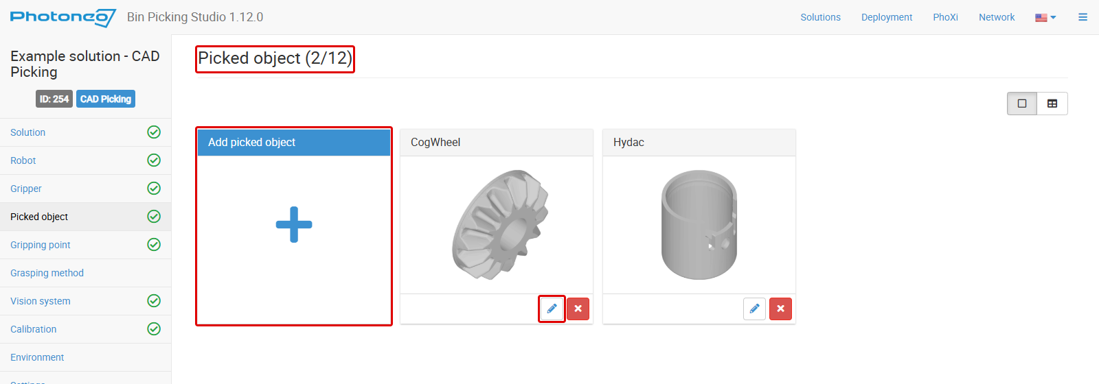
The Picked object page of the CAD Picking example solution. Red frames: the number of picked objects out of the maximum, Add picked object, and the Edit button of a picked object.
The title shows how many picked objects the solution has and how many it can have, for example Picked object (2/12). Each object has an Edit and a Delete button. The buttons in the top right corner switch between the card and the table view.
Adding or editing a picked object
Click Add picked object, or Edit on an existing object.
On the Model tab, fill in the fields below.
Click Save.
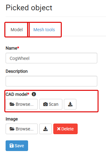
The picked object form. Red frames: the Model and Mesh tools tabs and the CAD model field.
Field |
Description |
|---|---|
Name (required) |
The name of the object. |
Description |
The Studio’s help suggests: “Always provide a clear description of the model or the version of your part. This information may come handy when examining older or unfamiliar projects.” |
CAD model (required) |
“A mesh in STL or PLY format with the model dimensions in [mm].” Browse… uploads a file, Scan takes the model from a connected 3D sensor, and the download button saves the current model. See CAD file. |
Image |
The picture shown in the picked object list. Delete removes your own image. |
The 3D viewer next to the form shows the model. Below it, the Studio shows the number of vertices and faces and the size of the model in mm.
The Mesh tools tab edits the uploaded or scanned model: cropping, simplification, filtering, normals and origin. See Mesh tools.