Integration Guide Universal Robots LS
Note: It is strongly recommended to read the Robot communication overview prior to this integration guide.
Note 2: It is strongly recommended to use the latest version of the integration guide included in the latest available version of the robot module. To download the robot module, please visit the official Photoneo website.
Contents
1 Prerequisites
Prior to the setup, please ensure that your robot controller meets the following criteria:
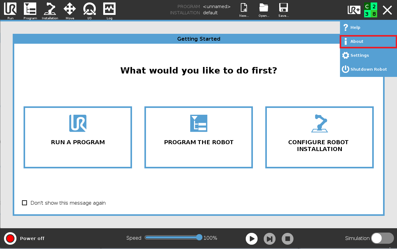
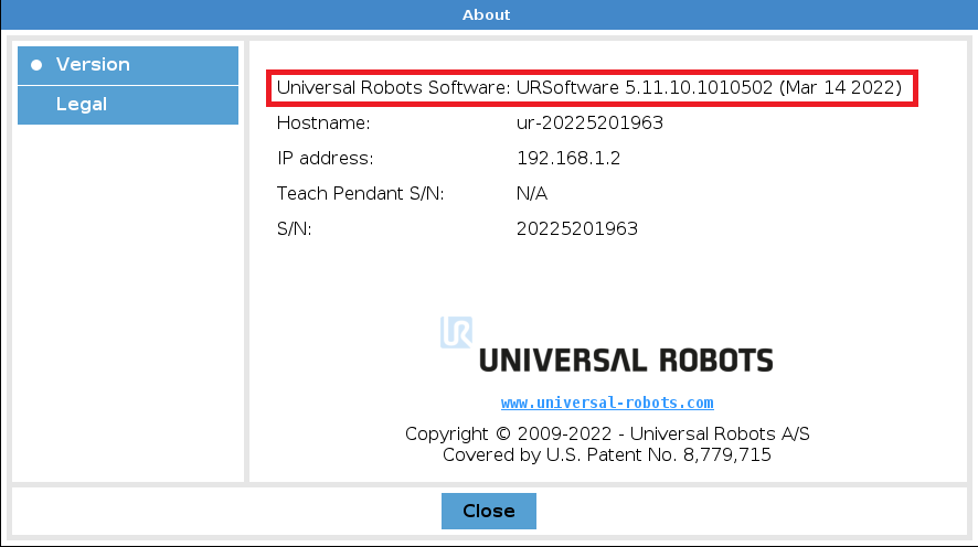
E-Series controller, software version 5.10 or higher
UR-Series controller, software version is yet to be determined
CB-Series is not officially supported anymore
This version of the robot interface was developed and tested using Universal Robots E-Series v5.22 and v5.11.
2 Robot controller setup
2.1 Network configuration
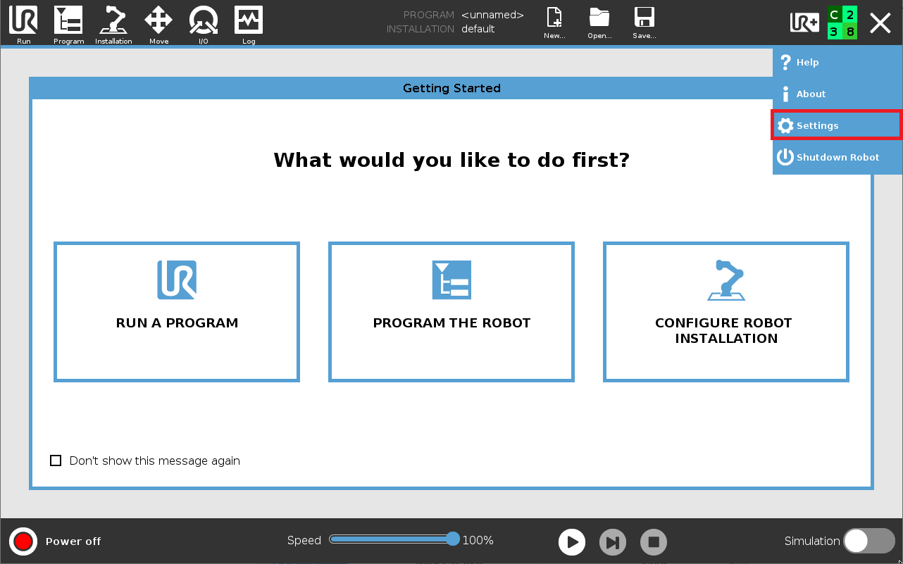
NOTE: Subnet Mask 255.255.255.0 equals a 24 bit subnet mask representation. See this table for more combinations.
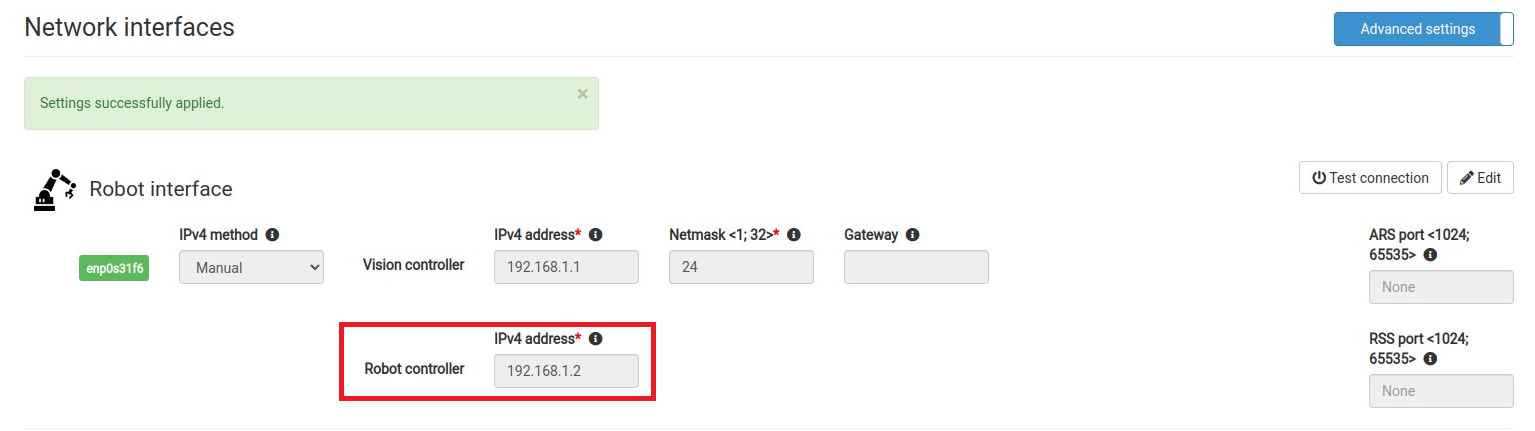
An example of matching network configuration on the Vision Controller side:
Vision Controller IPv4 Address: 192.168.1.1 / 24
Robot Controller IPv4 Address: 192.168.1.2 / 24 (as configured in the previous step)


2.2 Enabling Real-Time Data Exchange (RTDE)
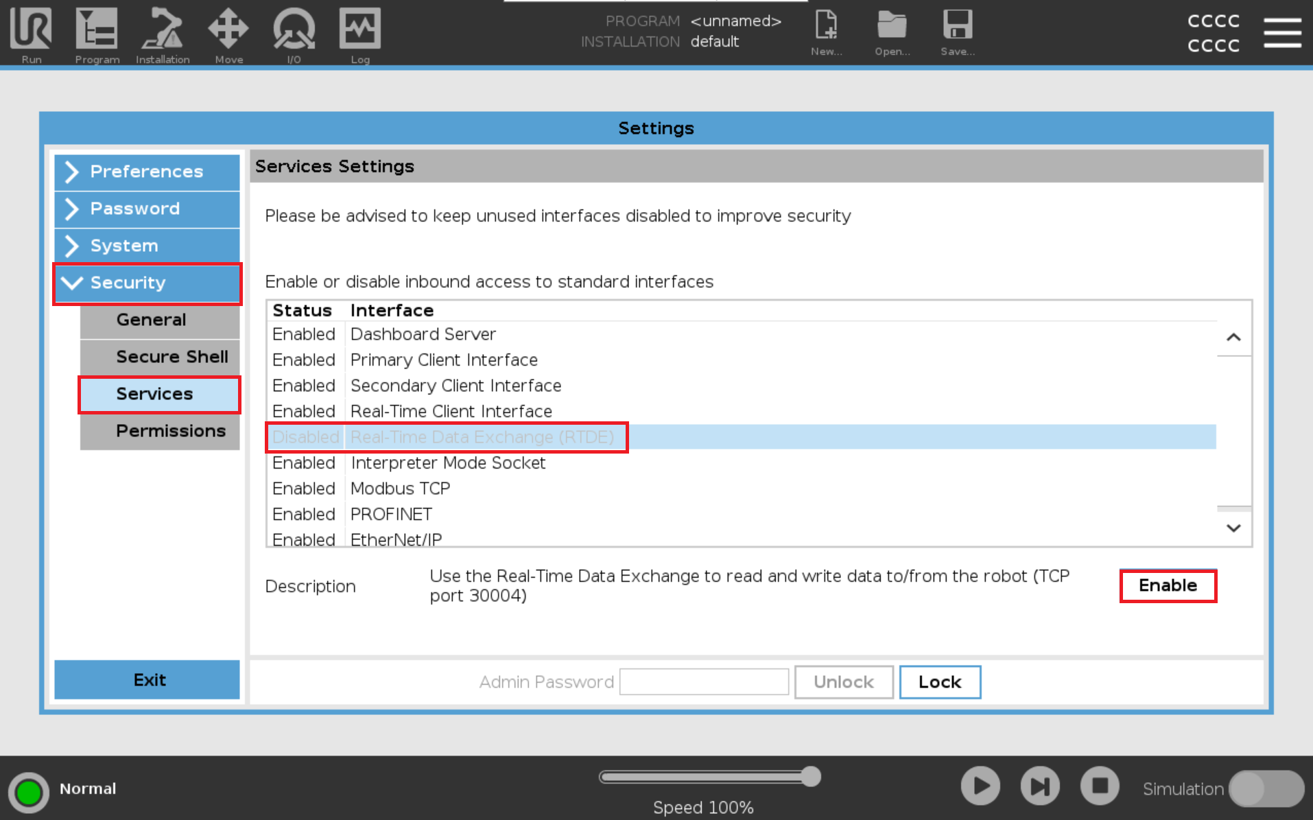
The State Server functionality (Calibration & Visualization) requires the Real-Time Data Exchange (RTDE) service to be enabled and running on the robot side.
2.3 Loading of Robot Module Files
The Photoneo UR robot interface consists of a single script file and several URP template programs:
photoneo_scripts
photoneo_locator.script
photoneo_examples
pho_calibration_basic_loc.urppho_calibration_auto_loc.urppho_main_basic_loc.urppho_main_basic_hand_eye_loc.urppho_main_basic_multi_vs_loc.urppho_main_change_solution_loc.urppho_main_get_status_loc.urppho_main_multiview_dynamic_loc.urppho_main_multiview_static_loc.urppho_main_reuse_scan_loc.urppho_main_change_bounding_box.urp
Only URP programs need to be copied - the script is already included in the URP templates!
There are 2 ways to copy files to the robot controller:
USB flash drive
File transfer protocols such as SCP, FTP or SFTP
USB flash drive approach
Copy the folders from the downloaded module archive onto a USB flash drive and plug the drive into the pendant or into the robot controller USB port.
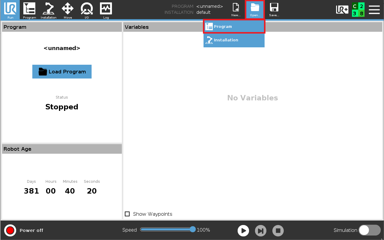

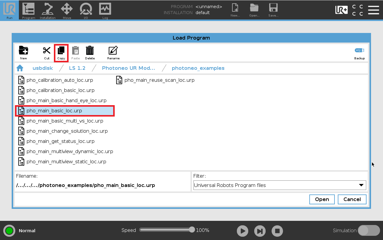
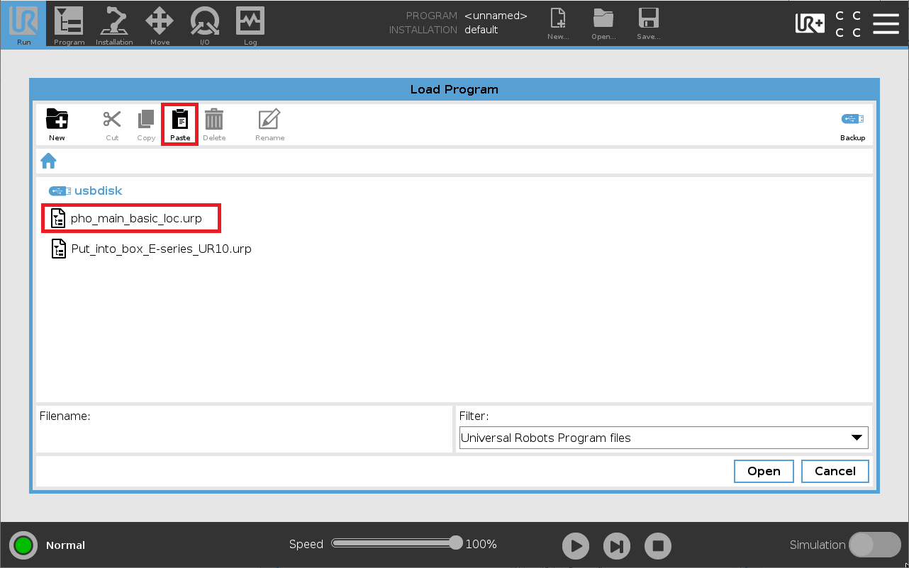
Repeat for all template URP programs you plan to use in your project.
File transfer protocol approach
It is possible to copy files to the UR Controller using remote access directly from your PC. Use WinSCP, FileZilla or another SFTP client. When creating the connection use the following configuration:
Protocol: SFTP
Host: Robot IP address
Port: 22
User:
rootPassword:
easybot
Alternatively, for situations where a command line interface is needed, use the following scp command to copy files:
$ scp -r Photoneo root@XXX.XXX.XXX.XXX:/programs/LS 1.5
2.4 Tool TCP Setup
TCP setup - Locator Studio reads the UR TCP pose during calibration and hand-eye scanning requests. What is reported by the robot to the vision system is the position of the tool according to the TCP configuration on the Installation TCP tab. Locator Studio prefers an “all zeros” tool configuration, as it compensates for the TCP offset directly on the vision system side. A zero tool configuration is also recommended for the calibration process.
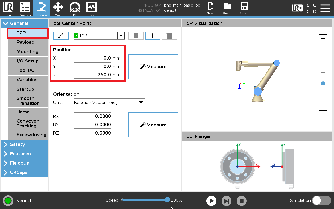
set_tcp command from the UR Scripting language manual and switch between the zeroed and non-zeroed tool.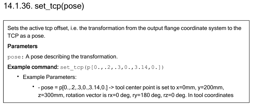
3 Robot module
The Robot module is designed to be easily integrated into existing applications.
Note: It is strongly recommended to read the Photoneo robotic API and Action requests documentation prior to this section (user login: customer, password: Ready2LearnHow2Pick).
3.1 Connection procedures
Warning: This procedure is contained in the photoneo_locator.script API section and must not be edited!
This procedure establishes the connection to the Action Request Server running on the Vision Controller, at the beginning of the program. Requests can only be sent after a successful connection has been established.
Connection procedure |
Description / Usage |
|---|---|
Connect to Action Request Server
pho_wait_for_server(server_ip,port = PHO_LOCATOR_PORT_DEFAULT,max_attempt = 1) |
Description
Function to establish a new connection to the Action Request Server (Vision Controller).
Input parameters:
Usage
The procedure should be called only once at the beginning of the program. Only after the connection has been established it is possible to send requests.
pho_wait_for_server("192.168.1.1")
Populates
PHO_ERR_CODE - error code [global variable] |
3.2 Request List
This section describes available API calls provided by the Robot module. These procedures are intended for high-level control of the Locator Studio application.
Note: These procedures are defined in the photoneo_locator.script API section and must not be edited!
Note: Procedures with optional parameter timeout have its default value set to -1. This means the timeout for receiving packets is infinite. Since the UR script has no means for detection of closing socket the robot program may be left hanging on this procedure when this situation occurs. Procedures without this parameter have hardcoded infinite timeout for receive.
Calibration requests
Request |
Input variables |
Output variables |
|---|---|---|
Calibration start request
pho_calib_start(solution_id,vision_sys_id) |
solution_id - solution IDvision_sys_id - vision system ID |
|
Calibration add point request
pho_calib_add_point(tcp_pose) |
|
|
Calibration save request
pho_calib_save() |
— |
PHO_ERR_CODE - error code [global variable]pho_calib_acc - resulting calibration accuracy [global variable]pho_camera_pose - resulting camera pose [global variable] |
Calibration stop request
pho_calib_stop() |
— |
|
Locator requests
Request |
Input variables |
Output variables |
|---|---|---|
Scan request
pho_request_scan(vision_sys_id,tcp_pose = PHO_NO_POSE) |
vision_sys_id - vision system IDtcp_pose - TCP pose [optional parameter - used only for hand-eye vision systems] |
Note: The response is received by the procedure Wait for scan completion. |
Meshing scan request
pho_request_trigger_scan(vision_sys_id,tcp_pose = PHO_NO_POSE) |
vision_sys_id - vision system IDtcp_pose - TCP pose [optional parameter - for hand-eye systems use get_actual_tool_flange_pose()] |
Note: The response is received by the procedure Wait for scan completion. |
Reuse last scan request
pho_run_loca_on_last_scan(vision_sys_id) |
|
Note: The response is received by the procedure Wait for scan completion. |
Change bounding box request
pho_request_change_bbox(vision_sys_id,bbox_id) |
vision_sys_id - vision system IDbbox_id - bounding box ID |
|
Get objects request
pho_request_get_objects(vision_sys_id,num_of_req_objects) |
vision_sys_id - vision system IDnum_of_req_objects - number of requested object poses |
PHO_ERR_CODE - error code [global variable]pho_object_poses - array containing received object poses as pose variables (p[x,y,z,ax,ay,az]), starts indexing from 0 [global variable]pho_number_of_objects - number of received object poses [global variable]pho_dimensions_x - object width [non-CAD solutions, global variable]pho_dimensions_y - object length [non-CAD solutions, global variable]pho_dimensions_rot - object rotation [non-CAD solutions, global variable]pho_nn_label - detected object label [AI solutions, global variable]pho_max_height - object height [Layer solutions, global variable]pho_angle - object angle [Layer solutions, global variable] |
Get vision system status request
pho_request_get_vs_status(vision_sys_id) |
|
PHO_ERR_CODE - error code [global variable]pho_num_localized - number of objects localized [global variable]pho_num_ready - number of objects ready for picking [global variable]pho_process_state - current state of the vision system [global variable] |
Solution requests
Request |
Input variables |
Output variables |
|---|---|---|
Change solution request
pho_request_change_solution(solution_id) |
|
|
Start solution request
pho_request_start_solution(solution_id) |
|
|
Stop solution request
pho_request_stop_solution() |
— |
|
Get running solution request
pho_request_running_solution() |
— |
PHO_ERR_CODE - error code [global variable]pho_running_solution - solution ID [global variable] |
Response receiving procedures
Response receiving procedures |
Input variables |
Output variables |
|---|---|---|
Wait for scan completion
pho_wait_for_scan_completion() |
— |
|
Communication check
Request |
Input variables |
Output variables |
|---|---|---|
Communication check request
pho_request_comm_check() |
— |
|
Get approach offset pose is an extra function that calculates an approach offset pose based on the selected method and axis.
Function |
Input parameters |
Returns |
|---|---|---|
Get approach offset pose
pho_get_approach_offset_pose(pho_object_pose,pho_offset_value,pho_method = PHO_METHOD_DEFAULT,pho_axis_name = PHO_AXIS_NAME_DEFAULT) |
pho_object_pose - target object posepho_offset_value - offset magnitude, in meterspho_method - offset calculation method [optional parameter, one of 'Tool Offset', 'Tool Plane', 'Base Offset', 'Base Plane']pho_axis_name - axis along which the offset is applied [optional parameter, one of 'X', 'Y', 'Z'] |
pose |
Method options:
'Base Offset'- adds the offset along the selected axis in the base coordinate system'Base Plane'- overrides the value along the axis in the base coordinate system'Tool Offset'- adds the offset along the axis in the tool coordinate system (TCP)'Tool Plane'- computes the intersection between the offset plane (base system) and the TCP along the selected axis
Usage of this function for setting up the approach/deapproach offset is described in more detail in 4.1 Set approach, deapproach offset parameters.
3.4 Example programs
There are several URP template programs available in the Photoneo UR module that demonstrate how to properly use the requests listed in 3.2 Request List for various use cases:
URP example |
Description |
|---|---|
pho_main_basic_locpho_main_basic_hand_eye_loc |
This simple example demonstrates the basic workflow: it shows how to connect to a vision controller, send a scan request, request object poses, receive the object poses, and execute picks. The example also illustrates error handling, as each function returns an error value assigned to |
pho_calibration_basic_locpho_calibration_auto_loc |
The basic calibration examples. Requirements: the initial calibration of the Vision System must be started and confirmed manually by the user on the Locator Studio side. Calibration steps:
Important: the calibration object (ball or marker pattern) must remain in its original position to ensure successful automatic recalibration. |
|
Same as The |
|
Same as It shows how to activate different solutions using |
|
Same as
These variables are commonly used for advanced decision-making, particularly to determine the optimal timing for starting the pick procedure. |
|
Static meshing example. Demonstrates stitching multiple scans together before localization, which is useful for complex scenes or large objects. The robot pauses at each scanning position to trigger and capture a scan. Requirements: the State Server must be operational throughout the process, and Procedure:
|
|
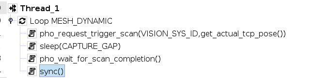
Dynamic meshing example. Uses the LS 1.5 integration of Photoneo Instant Meshing together with the Parallel Structured Light technique of the MotionCam-3D. Dynamic meshing cannot be used with standard PhoXi 3D Scanners. Requirements: Procedure:
|
|
Same as Procedure: perform a regular scan for VS1 to capture the scene, then for VS2 use |
|
Same as Procedure: prepare the Vision System with at least 2 bounding boxes and switch between them using |
3.5 Error handling
If an error occurs during the execution of the operation requested by the sent request the global variable informing about an error occurrence is set to true (PHO_OCCURED_ERR) and the error code is stored in the global variable PHO_ERR_CODE. It is recommended to implement adequate error handling for your particular application after each synchronous request and response receiving procedure.
Error codes together with their description and troubleshooting can be found here.
4 Runtime
Once the solution is fully configured on the Vision Controller side, finish the remaining steps on the robot side and run the Locator Studio program.
4.1 Set approach, deapproach offset parameters
The Locator Studio example programs provide a way to set up the approach and deapproach offset parameters, which are used by the pho_get_approach_offset_pose() function described in 3.3 Pick related functions.
Input parameters for pho_get_approach_offset_pose():
pho_object_pose- target object posepho_offset_value- offset magnitudepho_method- offset calculation methodpho_axis_name- axis along which the offset is applied
Approach offset configuration
The following variables define the approach behavior:
Variable |
Description |
|---|---|
|
Sets the offset distance, in meters |
|
Specifies the approach axis ( |
|
Selects the approach method, as a string |
Available approach methods:
'Base Offset'- adds the offset along the selected axis in the base coordinate system'Base Plane'- overrides the value along the axis in the base coordinate system'Tool Offset'- adds the offset along the axis in the tool coordinate system (TCP)'Tool Plane'- computes the intersection between the offset plane (base system) and the TCP along the selected axis
Deapproach settings are configured separately, in the Deapproach Offset Parameters folder.
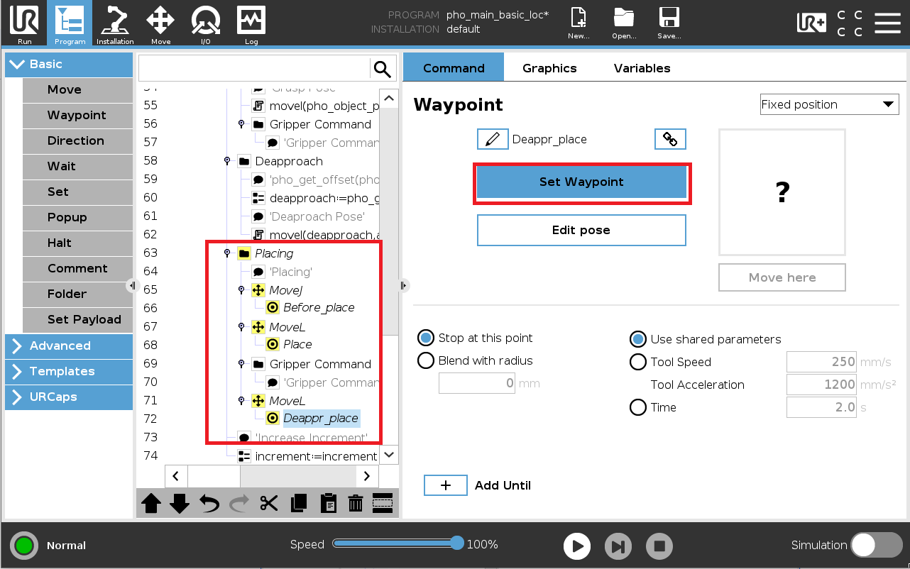
4.2 Teach positions
Scanning
Before_place
Place
deapproach_place
4.3 Prerequisites
Final pre-deployment checklist before running the Locator Studio interface from the robot side. Make sure that:
The Locator Studio solution is properly configured on the Vision Controller side
Network setup on the robot side is completed and the State Server is working
All Vision Systems defined in the solution are calibrated
All local poses in the main program have been touched up properly
Gripper procedures are prepared and working
4.4 Running the pho_main_basic_loc program
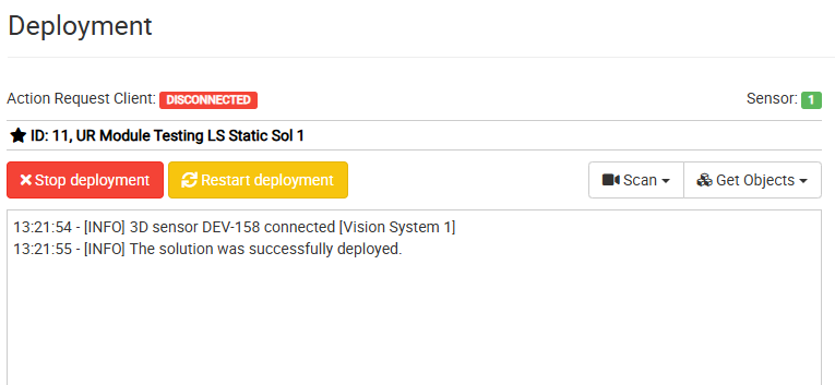
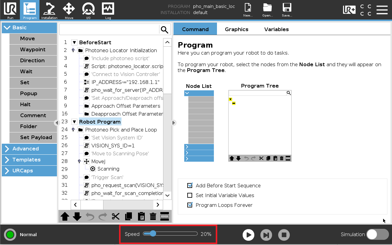
NOTE: It is strongly recommended to reduce the override speed to 20% before running the program for the first time.
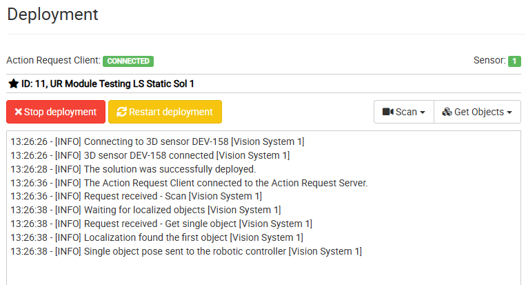
If there is a pickable object in the scene and the robot controller has received its Cartesian pose, the robot should start moving towards the first object.
If the robot movement looks correct, continue moving the robot towards the first target and verify that the path is correct. If the robot is too far from the object or pushes the object too deep, adjust the object origin or the tool TCP setup.
Once the robot movement looks correct, set up your own placing routine and gradually ramp the speed back up to 100%.
At this point, the robot should be successfully picking and placing objects using the Photoneo Universal Robots interface. Refer to the example programs in 3.4 Example programs as a guideline while further tuning your application.
5 Robot module update
To update an existing robot module to a version compatible with the Locator Studio you are using, please follow these steps:
Load the new script - copy the new version of
photoneo_locator.scriptto the robot controller and replace the old one.Review API changes - carefully read through the API changes introduced in the new version of the robot module and update your existing API calls in the main program as necessary to align with these changes.
To check the version of the photoneo_locator.script, check the script’s header and look for the library version.