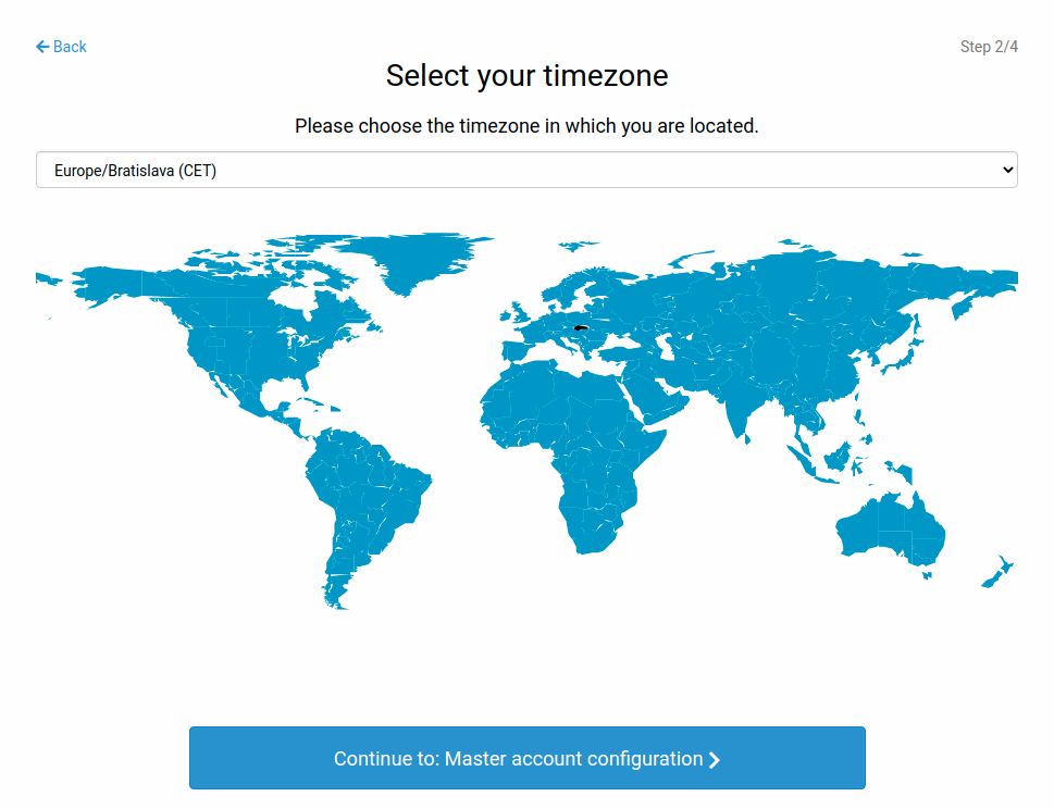
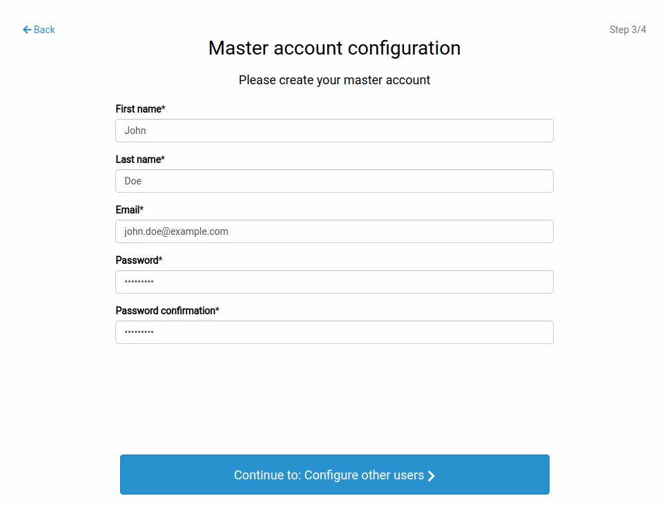
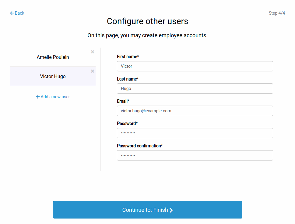
Initial setup
This chapter will walk you through the initial setup of your vision controller; it contains a description of the Studio package contents, an overview of the vision controller and its peripherals and it also covers the necessary steps of the initial configuration of the Studio.
Contents
1 Hardware setup
1.1 Studio package contents
The Studio package consists of the following hardware components:
Vision Controller
An industrial-grade device running Ubuntu 22.04 with pre-installed Bin Picking Studio / Locator Studio
|
|
Power adapter (100 - 240 VAC / 24 VDC, 280W) |
|
Power cable |
|
DC power cables |
|
3-pin plugable terminal block |
|
Calibration ball |
|
Calibration board |
|
HDMI dummy plug
For use without a physical monitor
|
|
Wall mount brackets |
|
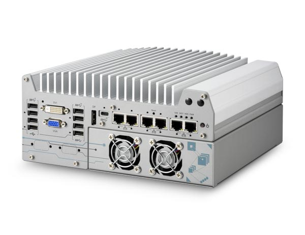
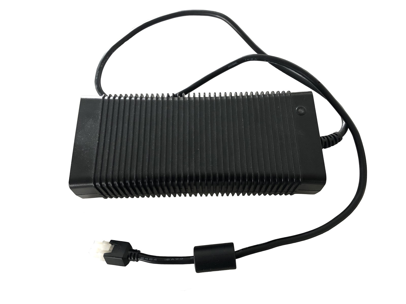

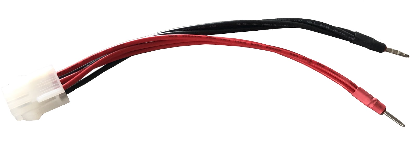
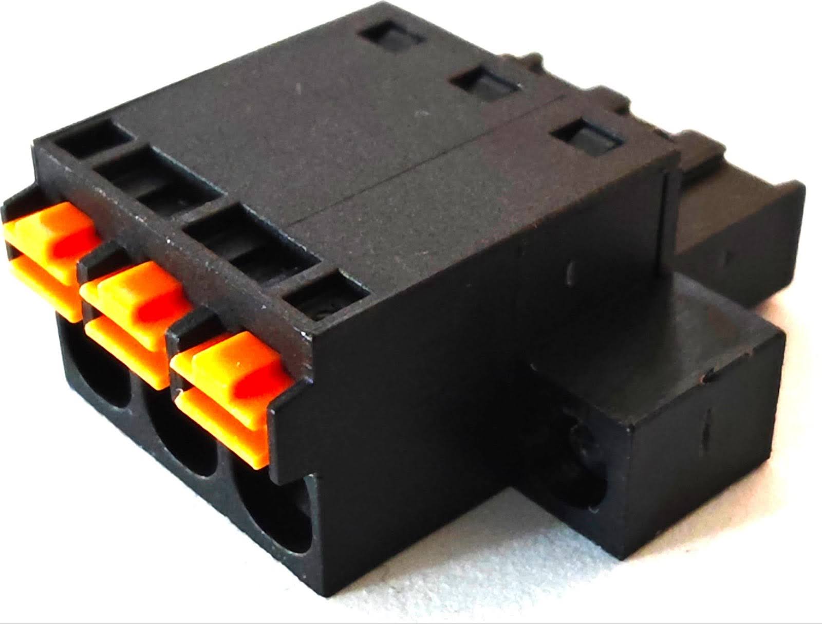
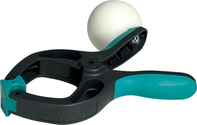
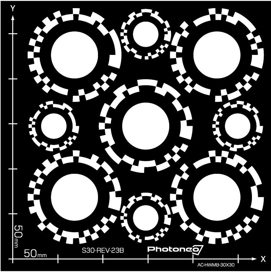
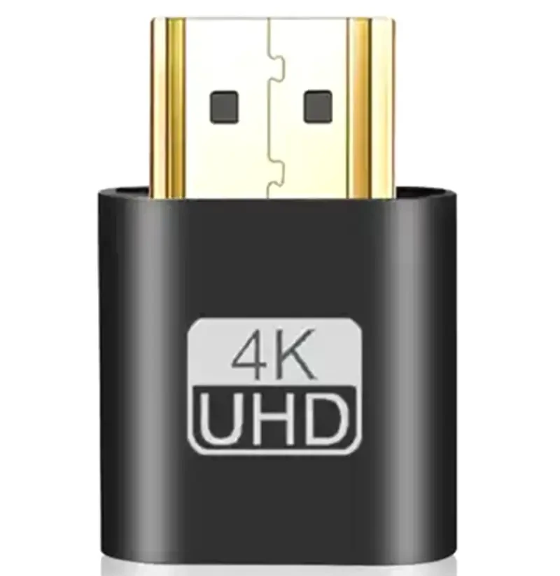
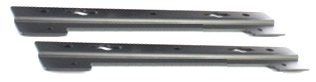
Image 1 - Hardware components of the Bin Picking Studio / Locator Studio package
1.2 Vision controller overview
There are two types of supported vision controllers with slight differences on the outside.
On the front side of both of them there are:
6x Ethernet ports with dedicated functions - from left to right:
Sensor interface 1
Sensor interface 2
Sensor interface 3
Sensor interface 4
Network interface
Robot interface
Unsupported display ports (must not be used)
On the back side of both of them there are:
Supported display ports
configuration differs based on the exact GPU model
Power socket
1.3 Connection of peripherals
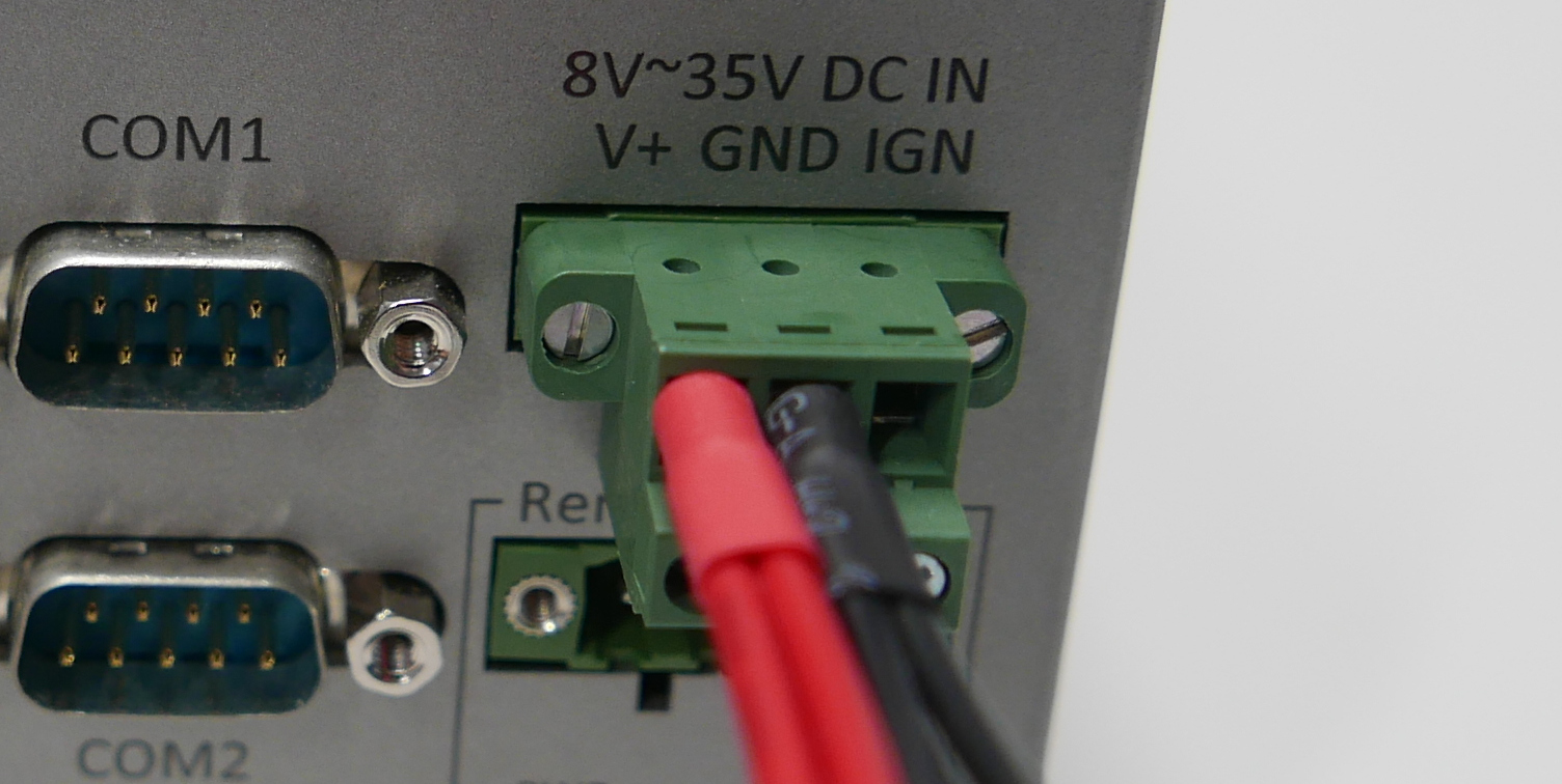
Note: The vision controller is configured to turn on automatically when the power source is connected.
DisplayPort
HDMI
DVI
The usage of multiple displays and touchscreen displays is also supported.
Tip: Onscreen keyboard can be enabled in the Ubuntu settings. Open the Settings panel, navigate to the category Accessibility, and in the section Typing enable the Screen Keyboard. The keyboard will appear every time a text field is selected.
It is also possible to operate the Studio remotely without the use of a physical display, however, in that case a dummy plug for display emulation is required. Please refer to the Remote access to find out more about ways to control the Studio remotely.
1.4 Installation guidelines
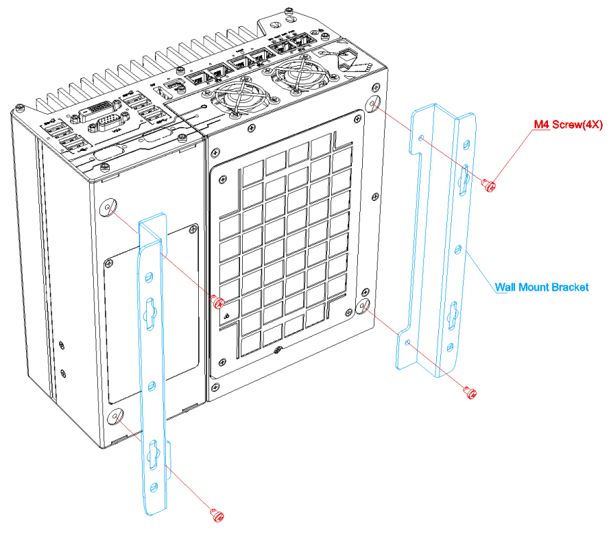
When placed onto a flat surface, it is recommended to install the wall mount brackets onto the bottom of the vision controller to allow better air intake to cool the graphics card.
You will need to remove the four rubber stands at the bottom of the vision controller if they have been attached. You can attach them to the brackets afterwards.

The ambient operating temperature shall not exceed 50°C. If the vision controller is placed in an enclosure, ensure adequate ventilation and cooling.
2 Welcome page