Integration Guide Estun BPS 1.12
Integration guide for Estun Robots with Bin Picking Studio version BPS 1.12.
1. Robot Controller Setup
1.1 Initial Setup and Configuration
For detailed information about the Estun robot controller, please refer to the official Estun robot controller documentation. Below is robot controller ERC3-C1 used in this manual:
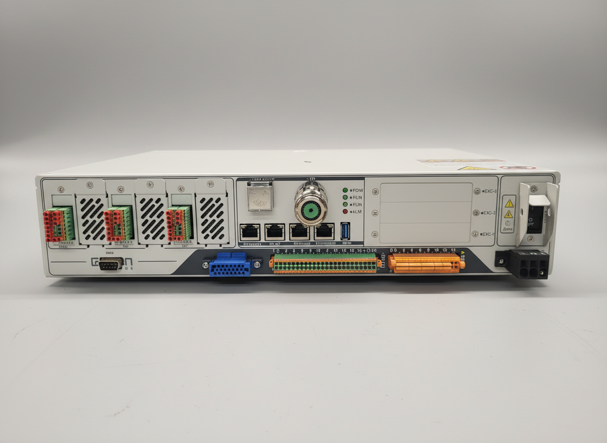
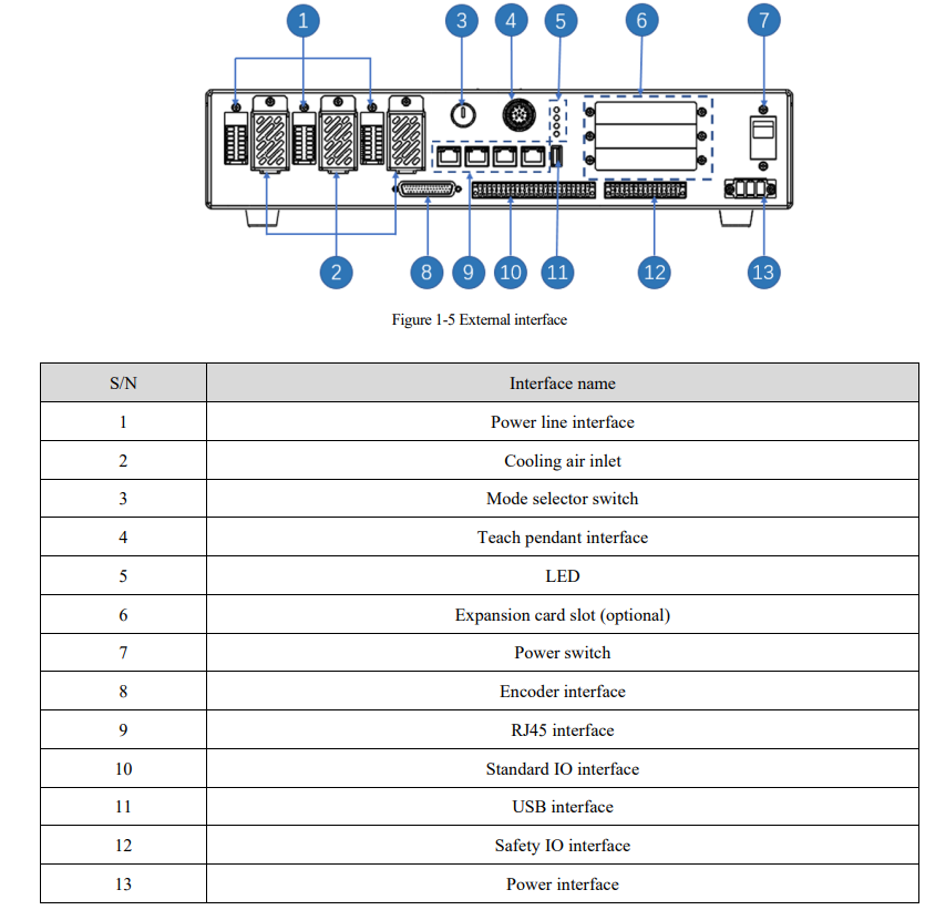
1.2 Network Configuration
There are multiple Ethernet ports to choose from on Estun Robot Controller. For user TCP/IP socket connections, Ethernet 2 and Ethernet 3 are reserved. It is up to the user which port is selected for communication, in this tutorial we will use Ethernet 3 for communication with Photoneo Vision Controller.
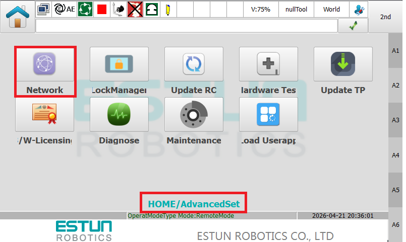
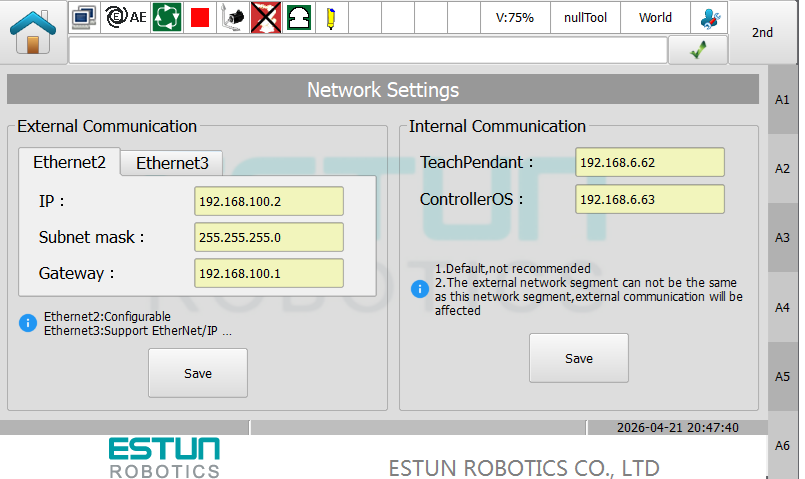
In order to change IP config, click Home → Advanced Set → Network.
Type IP address and Subnet Mask for Robot Controller. As a gateway you can use Vision Controller IP. Configuration used in this manual is 192.168.1.2 and 255.255.255.0.
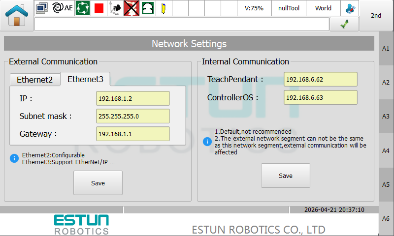
Click the Save button to confirm the changes.
Note
Subnet Mask 255.255.255.0 equals 24 bit subnet mask representation. See this table for more combinations: https://dnsmadeeasy.com/support/subnet
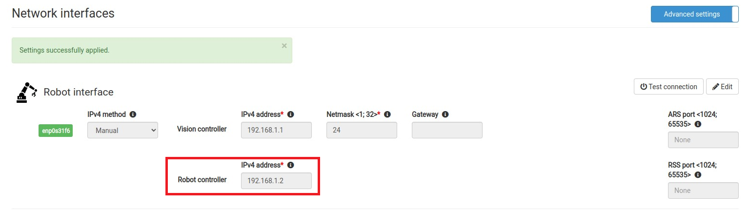
An example of matching Network configuration on Vision Controller side
Vision Controller IPv4 Address: 192.168.1.1 / 24
Robot Controller IPv4 Address: 192.168.1.2 / 24 (as configured in the previous step)
You can also use Test Connection button on Photoneo Vision Controller Network page to ping Estun Robot Controller from Photoneo Vision Controller
Based on the result of Test Connection (ping command) you will get a Robot Available or Robot Unavailable message pop up. If the robot is unavailable, double check cabling and network configuration.

1.3 Second Network interface for PC and Estun Editor connection (optional)
It is recommended to configure another (in our case Ethernet 2 port) for remote access using the Estun Editor application on a PC. To prevent network conflicts, assign this interface a static IP address on a different subnet than the one used for connection to Photoneo Vision Controller.
For example, a valid configuration for this Port would be:
IP Address: 192.168.100.2
Subnet Mask: 255.255.255.0
Example IPv4 configuration of PC running Estun Editor: 192.168.100.1 / 255.255.255.0
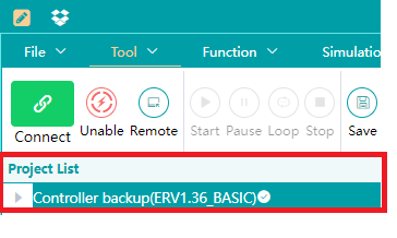
If connection to Estun robot fails, or there is no Controller data structure visible after connection, close Editor and start it over with Run As Administrator options. This structure should be visible in Editor:
1.4 Import and Enabling of State Server
The State Server is an essential component that provides real-time robot state data utilized in calibration routine and 3D visualization. On the Estun platform, this functionality is provided by a python script named PhoStateServer.py. The deployment procedure is detailed in the following steps.
Warning
PC with client supporting SFTP file transfers (WinSCP, MobaXterm, etc.) will be needed.
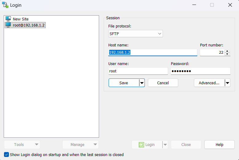
Establish connection to Estun robot from your PC using WinSCP, MobaXterm or another SFTP client
using following credentials: Login: root, Password: ERC654321
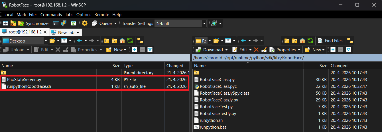
Copy PhoStateServer.py and from Photoneo Estun Module to /opt/runtime/python/sdk/libs/RobotFace/
Set permissions on both copied files to Octal 0777.

Go to /opt/runtime/ and open file startSys.cmd
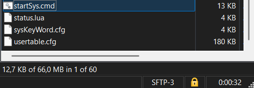
At the bottom of this file copy and paste following text

# Launch of Photoneo State Server
echo “[$(date)] Starting Estun-Photoneo’s Robot State Server…” >> /var/log/photoneo_server.log
cd /opt/runtime/python/sdk/libs/RobotFace/
./runpythonRobotFace.sh > /dev/null 2>> /var/log/photoneo.log &
Reboot Estun robot controller to apply these changes.
1.5 Tool TCP Setup
Bin Picking Studio is designed to operate with a Tool Center Point (TCP) that is zeroed relative to the robot’s end flange. On Estun robots, this corresponds to the default zeroed tool configuration. The explicit definition of TCP offsets on the robot controller is not necessary, as Bin Picking Studio internally calculates and compensates for these values. However, a custom TCP can still be defined if it is required for other subroutines within the larger robot application. For the purposes of this manual we used one toolPhotoneo with Z offset Z = 110mm.Tool data can be found in Data → Global → Tool
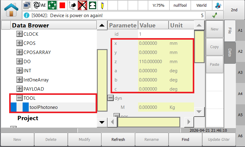
Use of SetTool(TOOL) command is recommended whenever it is necessary to force use of the proper tool frame. For example for scan and calibration requests, we always need “nullTool” but for example when picking based on the result of Get Object Pose, the real physical tool e.g. toolPhotoneo needs to be selected. When picking based on Trajectory request, tool setup doesn’t matter as we use joint based trajectories and TCP is compensated on the BPS side.
1.6 State Server + Visualization of Robot Pose
If State Server has been uploaded and configured on the Estun side, the Photoneo Bin Picking Studio will automatically connect to the 11004 port and read the current Joint Poses + Cartesian Tool Position from the Estun robot. While joint poses are used for robot visualization purposes, Cartesian TCP data are essential for calibration as well as all Hand Eye scan requests. See real robot pose on environment page below:
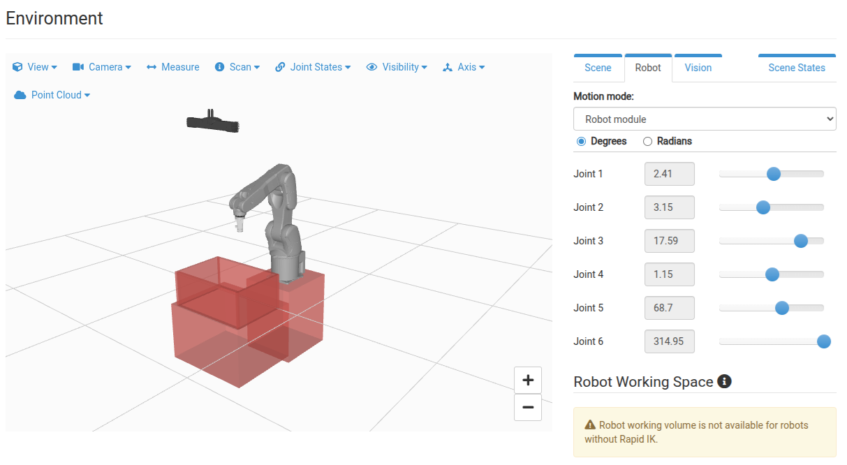
If State client is connected to robot it means that current Joint and Tool data are being streamed from Robot to Bin Picking Studio approximately at 10 Hz. Visualization of robot pose on Environment Page as well as Calibration should work now.
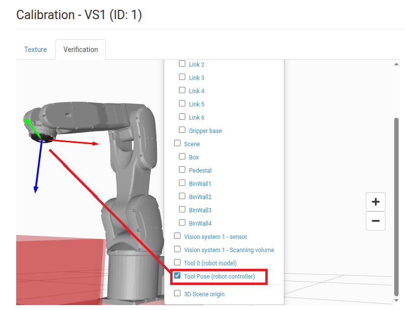
You can visually verify whether correct zeroed tool pose is being reported if you start calibration and switch from Texture to Verification Tab and enable visualization of Tool Pose (robot controller) in the Axis menu. The frame marker should be centered on the flange with the Z axis pointing down and it should be identical to the Tool0 (robot model) frame.
1.7 Importing Bin Picking Studio Module
The default method to import the Photoneo Estun BPS module on Robot is via USB Flash Drive.
To perform a USB file transfer first copy the ESTUN_BPS_1_12_0.er folder onto your USB drive. On the Estun pendant, navigate to the Project menu, scroll down the sidebar, and select the Loader button to open the file transfer window.
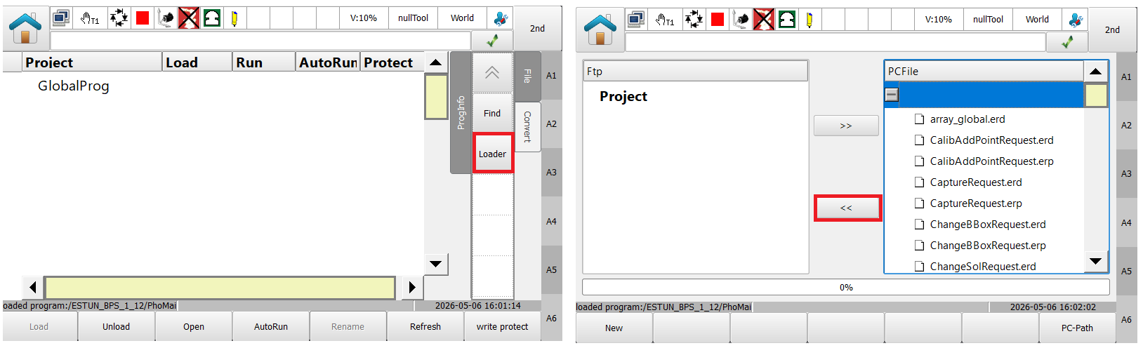
Locate the ESTUN_BPS_1_12_0.er folder on the USB drive and click the Transfer button to initiate the copy process. All files within the BPS folder will then be transferred to the Estun robot system.
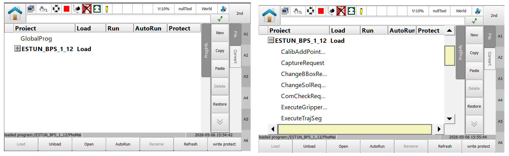
If there are no errors, it should be possible to load the ESTUN_BPS_1_12_0 project directly.
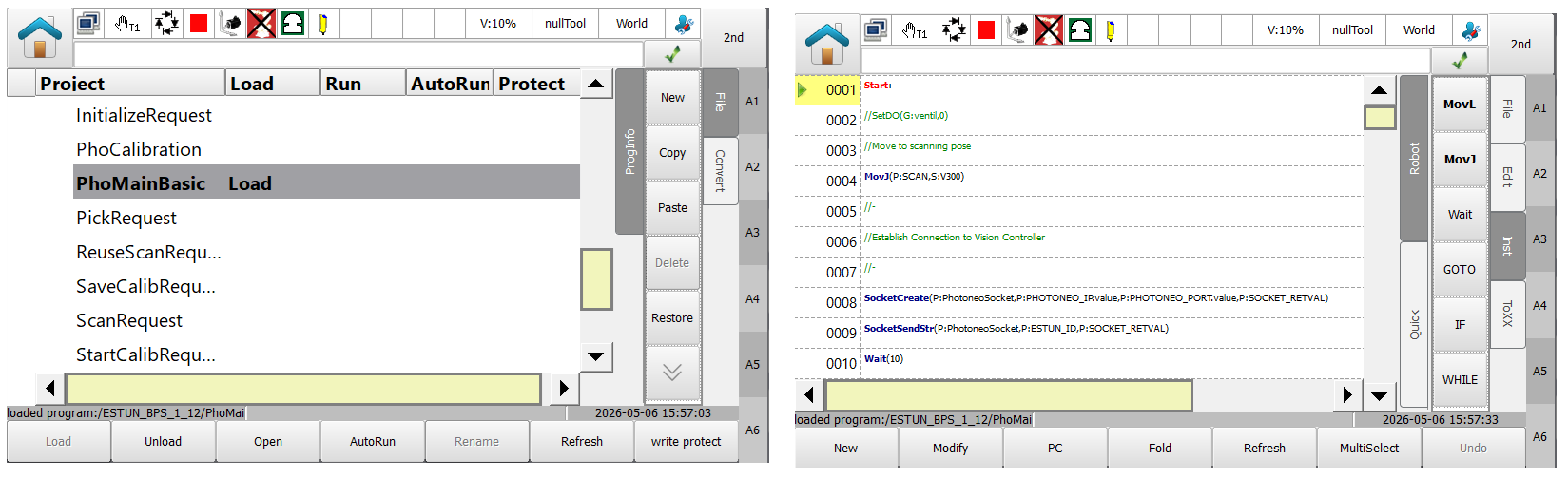
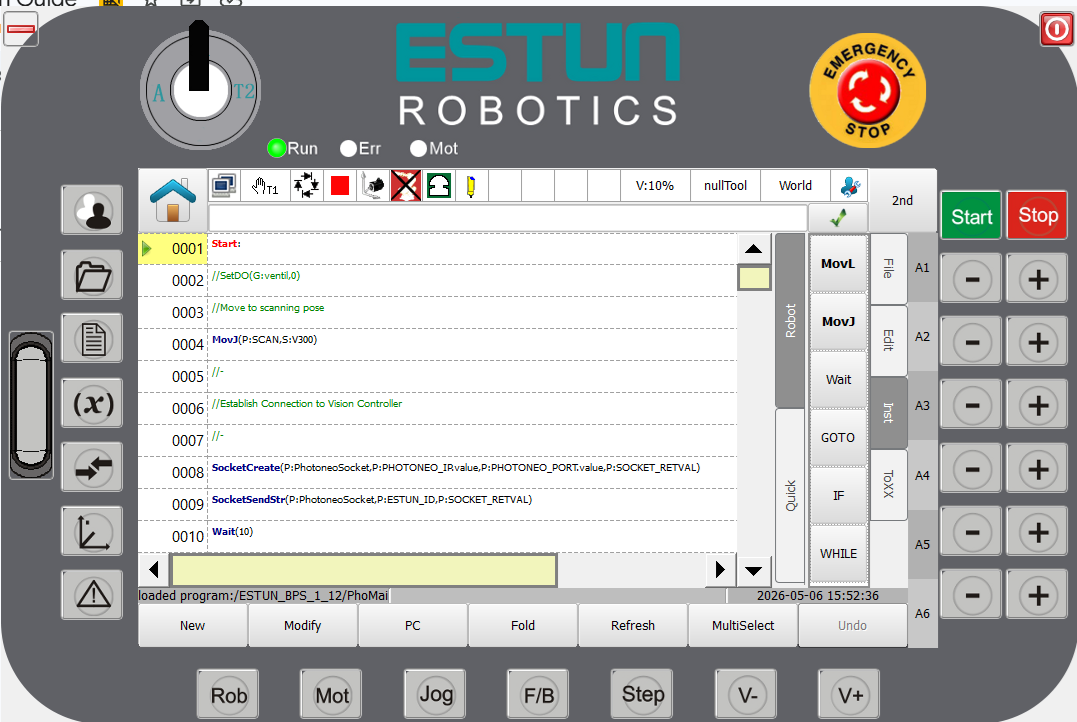
Once loaded, the project’s status in the Project List will clearly display as “loaded”. For execution, you can select the program to be run while in Playback mode and then click “PC” to ensure it starts from the first line. Alternatively, a program configured with the “self-start” function will automatically load when the remote mode is enabled by the user.
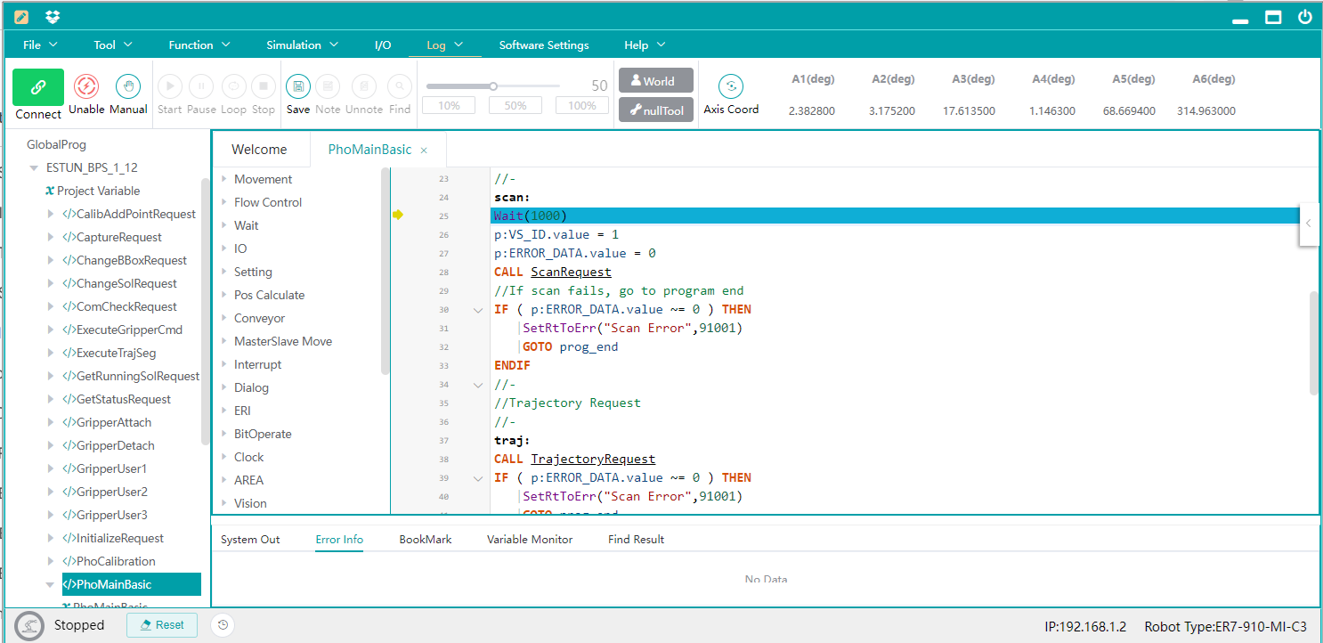
After importing is completed, it is possible to sync the Estun Editor with the robot controller as editing of programs can be done on the PC side. Just be aware that as of April 2026 there are certain limitations on Editor side and not all commands can be properly added or modified on Editor side. If struggling just comment the line of code and recreate it on the pendant side.
2. Robot Module
Note
It is strongly recommended to read the Photoneo robotic API prior to this section. (user login: customer, password: Ready2LearnHow2Pick).
2.1 Connection to Photoneo Vision Controller
Note
Establishment of connection to the Action Request Server running on the Vision Controller side happens at the beginning of each Main Program. Three global constants are important in this step:
PHOTONEO_IP - IP address of port on vision controller side
PHOTONEO_PORT - Port number used by Action Server (by default 11003)
ESTUN_ID - STRING robot identificator [DO NOT CHANGE]
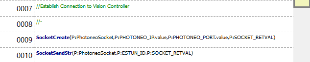
Change PHOTONEO_IP in project STRING variables to match the IP address of the Vision Controller you’re connecting to, in case of this tutorial it is 192.168.1.1.
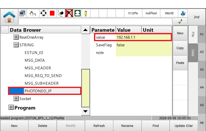
Requests can be sent to the Vision Controller only after a connection has been established. Successful connection is visualized by green Connected indicators on Deployment page after program on Estun side is started, see image below:

2.2 Request List
This section describes available API calls provided by the Robot module. These procedures are intended for high-level control of the bin picking application.
Note
These procedures are defined in the communication backend and must not be edited!
Request |
Program Name |
Input |
Populates |
|---|---|---|---|
Initialize |
InitializeRequest |
p.VS_ID (also uses p.START_POS_VSx and p.END_POS_VSx project poses for the selected VS) |
p.ERROR_DATA |
Scan Regular |
ScanRequest |
p.VS_ID |
p.ERROR_DATA |
Capture (Meshing Static) |
CaptureRequest |
p.VS_ID (current flange pose auto-read at call time via GetCurCPos) |
p.ERROR_DATA |
Reuse Scan |
ReuseScanRequest |
p.VS_ID |
p.ERROR_DATA |
Trajectory |
TrajectoryRequest |
p.VS_ID |
p.ERROR_DATA, g.PHOTONEO_TRAJ[] (APOSARRAY[1000] of waypoints), p.TOTAL_TRAJ_WPT_CNT, p.TRAJ_SEG_START_IDX[], g.GRIPPER_OPER_ARR[] (gripper operations) |
Pick |
PickRequest |
Uses trajectory data already stored in g.PHOTONEO_TRAJ[] and p.TRAJ_SEG_START_IDX[] by TrajectoryRequest |
None |
Get Vision System Status |
GetStatusRequest |
p.VS_ID |
p.ERROR_DATA, p.INFO_NUM_LOC, p.INFO_NUM_PICKABLE p.INFO_VS_STATUS |
Change Solution |
ChangeSolRequest |
p.SOL_ID |
p.ERROR_DATA |
Start Solution |
StartSolRequest |
p.SOL_ID |
p.ERROR_DATA |
Stop Solution |
StopSolRequest |
None |
p.ERROR_DATA |
Get Running Solution |
GetRunningSolRequest |
None |
p.ERROR_DATA, p.RUNNING_SOL |
Change Bounding Box |
ChangeBBoxRequest |
p.VS_ID, p.BBOX_ID |
p.ERROR_DATA |
Change Environment |
ChangeEnvRequest |
p.ENV_ID |
p.ERROR_DATA |
Calibration Start |
StartCalibRequest |
p.SOL_ID, p.VS_ID |
p.ERROR_DATA |
Calibration Add Point |
CalibAddPointRequest |
None |
p.ERROR_DATA |
Calibration Save |
SaveCalibRequest |
None |
p.ERROR_DATA, p.INFO_CALIB_ACC |
Calibration Stop |
StopCalibRequest |
None |
p.ERROR_DATA |
Com Check |
ComCheckRequest |
None |
p.ERROR_DATA |
Note
Estun BPS module uses several global variables that are not copied during import to prevent rewriting existing configurations on customer robots. Add following variables to global list:
g.PHOTONEO_TRAJ (APOSARRAY[1000])
g.GRIPPER_OPER_ARR(INT ARRAY[10])
g.toolPhotoneo[TOOL]
2.3 Bin Picking procedures
The bin picking operation is invoked by the PickRequest function call. This request orchestrates the execution of the bin picking trajectory operations. The following table provides an overview of the bin picking procedures as defined in the customer definitions section of the script.
Request |
Description |
|---|---|
|
Description: An orchestrator of execution of the bin picking trajectory operations. Goes over the OPER_ORDER array and calls Trajectory or Gripper execution routines accordingly. Also feeds trajectory start and end waypoints with values according to segment lengths as stored during Trajectory Receive |
|
Description: Continuous trajectory execution - runs through all trajectory waypoints with a FOR loop using the |
|
Description: Trajectory execution that stops at the last point of the trajectory (fine positioning) - runs through all trajectory waypoints with a FOR loop using the |
|
Description: Gripper command execution orchestrator function - calls gripper command function based on received gripper data |
|
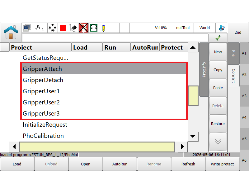
Description: Empty placeholder for Gripper Attach function. Fill with appropriate gripper commands based on your application |
|
Description: Empty placeholder for Gripper Detach function. Fill with appropriate gripper commands based on your application |
|
Description: Empty placeholder for Gripper User functions. Fill with appropriate gripper commands based on your application |
|
Description: Empty placeholder for Gripper User functions. Fill with appropriate gripper commands based on your application |
|
Description: Empty placeholder for Gripper User functions. Fill with appropriate gripper commands based on your application |
2.4 Bin Picking speed and blending parametrization
Bin Picking Studio supports up to 10 trajectory segments per single bin picking trajectory. The default number of segments is 4, if needed, additional segments can be configured on the Grasping method page in the BPS solution.
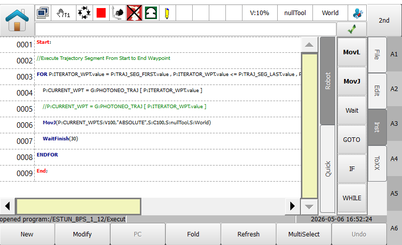
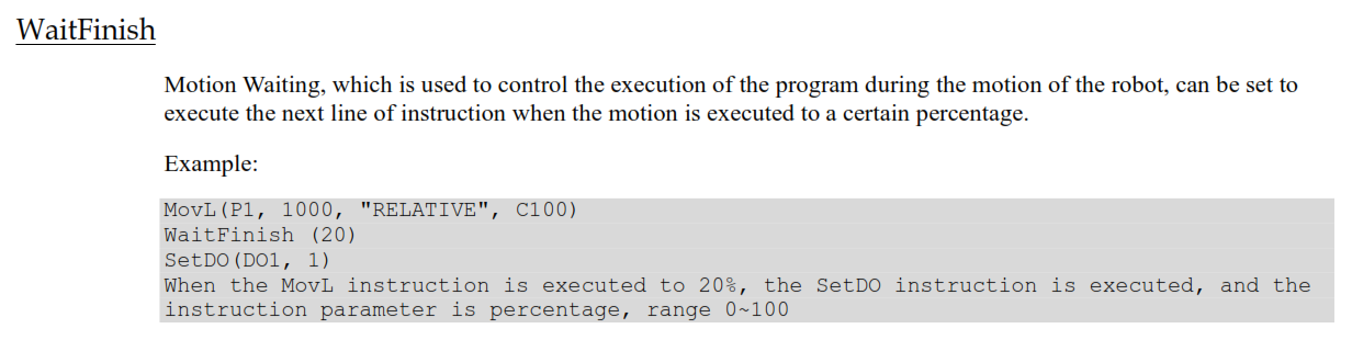
To customize the robot’s speed and smoothness for a specific segment, feel free to experiment with MOVJ arguments on line 6 as shown in the image above. An important step in this execution loop is WaitFinish, since it allows the Estun motion interpolator to look ahead for the next MOVJ instruction while the current MOVJ is still being executed. On ER7-910-MS-CE the best results were achieved with 30% setting, but it might vary based on density of trajectories and robot size.
2.5 Example Programs
There are several Estun Template Programs available in Photoneo Estun module that demonstrate how to properly use requests listed in section 2.2 for various use cases:
Program Example |
Description |
|---|---|
|
Description: The basic bin picking main program. Demonstrates the complete workflow for an Estun robot Program flow:
Error handling:
Error handling is included at each step using |
|
Description: The calibration main program for an Estun robot. Program flow: Goes through 9 calibration poses by:
Error Handling:
On any |
|
Description: Bin picking main program for a two-Vision-System setup, alternating between VS1 and VS2 each cycle.
Program Flow: Initialize VS1, Initialize VS2 -> set |
|
Description: Bin picking main program that alternates the active Bounding Box between each pick cycle. Demonstrates dynamic bounding box switching within a single running program
Program Flow: Initialize ( |
|
Description: same workflow as PhoMainBasic but with solution management.
On startup,
Error handling:
For |
|
Description: Bin picking main program that alternates the active Environment Scene between each pick cycle.
Program Flow: Initialize ( |
|
Description: Bin picking main program that polls |
|
Description: Bin picking main program for Static Meshing (multi-view capture) workflow.
Program Flow: Initialize ( |
|
Description: Bin picking main program for a two-Vision-System setup where VS1 performs a full Scan and VS2 reuses the last scan result. Demonstrates the |
|
Description: Bin picking main program that adds Communication Check calls at key points to verify the connection is alive. Useful for detecting network dropouts mid-cycle; raises error eid=91004 (‘Robot Disconnected’) if ComCheck fails.
Program Flow: Connect -> ComCheck -> Initialize ( |
3. Runtime
Once the solution is fully configured on the Vision Controller side, it is time to finalize the remaining steps on the robot side and proceed to executing the bin picking program.
3.1 Teach Positions
After Loading BPS_1_12_0.er project or another template, there are a couple of poses that need to be touched up before running the program. See APOS declarations below:
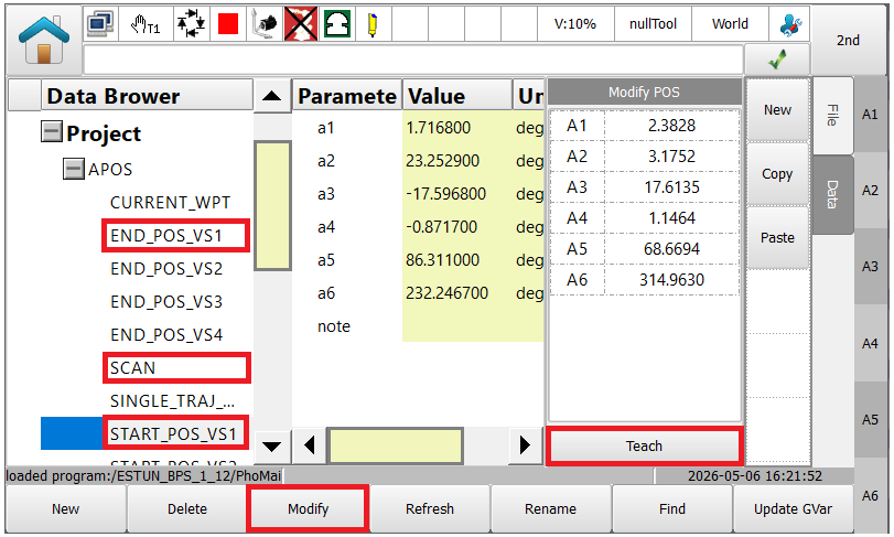
For a basic solution with a single vision system 3 poses need to be modified: SCAN, START_POS_VS1 and END_POSE_VS1. Important poses are START_POS_VS1 and END_POSE_VS1 because these define initial and final trajectory waypoints and are required during the initialization request for each vision system. Usually start and end positions are touched up in a way that a robot tool is located above the center of the bin. SCAN pose for static sensors should be taught outside of scanning volume so the robot is not under sensor when scanning.
Three poses mentioned above are located under Data → PROJECT → APOS and can be modified easily. Jog the robot to desired pose and hit the Modify and Teach button on the pendant to store new joint values to the APOS variable .
Note
There are also local poses defined directly in the placing area of the program. Make sure to touch up those accordingly as well.
3.2 Gripper commands
Gripper procedures are located within BPS_1_12_0.er project and by default are empty. It is up to a user to configure proper IO commands for particular operations.
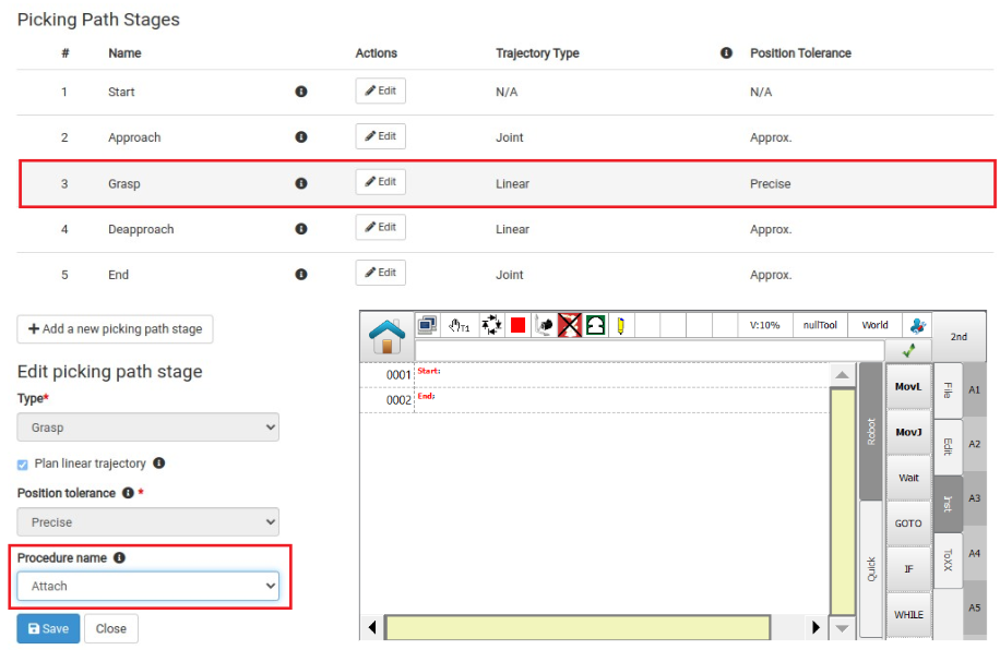
Grasping Methods Page in the Bin Picking Studio enables users to configure a gripper command to be executed at each bin picking trajectory major waypoint. For example, if the Attach Procedure is defined at the Grasp Waypoint, PickRequest procedure will call the GripperAttach subprogram after reaching Grasp waypoint.
3.3 Calibration
There are 2 methods of calibration available in Bin Picking Studio:
Sphere based calibration - for statically mounted sensors
Marker pattern based calibration - for carried or Hand Eye mounted sensors
For both methods it is required to capture a calibration object from 9 poses with sufficient variance in tool pose data. It is always recommended to use nullTool as default frame, using non-zero tool or user frame may result in skewed calibration results.
Calibration can be done directly without even using Estun Module Calibration procedures. This can be achieved by starting Calibration on the BPS side, jogging the robot from point to point and manually adding points on the BPS side will do the job. However for production setups where recalibration is expected, it is recommended to record calibration points into the program and ensure that transition between these poses will be collision free.
Estun Module provides a PhoCalibration program template. By default Calibration Start/Save/Stop function calls in PhoCalibration are commented out so it will only add points programmatically but it these commands are uncommented and proper vision system and solution IDs are set fully automatic recalibration without touching vision system at all can be easily achieved.
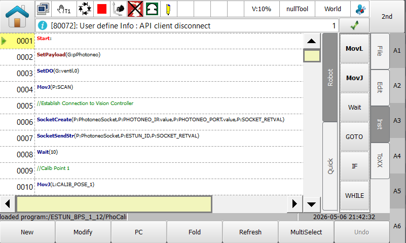
In general, calibration error should be below 3mm. Use the verification tab to check if the point cloud overlay over the robot body or gripper matches perfectly. Any discrepancy needs to be investigated because it can lead to collision. Most common issues: wrong Tool Frame values, incorrect gripper model orientation, incorrect robot model selection, encoders zeroing, flimsy robot base etc.
3.4 Runtime Prerequisites
Final pre deployment check before running bin picking interface from the robot side
Make sure that:
Bin Picking solution is properly configured on the Vision Controller side
Network Setup on Robot Side is completed and State Server works
All Vision Systems defined in solution are calibrated
Start and End Pose for all Vision Systems have been touched up
All local poses in main program have been touched up properly
Gripper procedures are prepared and working
3.5 Running PHO_MAIN_BASIC program
Deploy your solution. The Action Request Client (Robot) status on the Deployment page should be DISCONNECTED from the Action Request Server, if the communication hasn’t been established yet.

Note
It is strongly recommended to decrease the override speed to 10% before running the program for the first time.
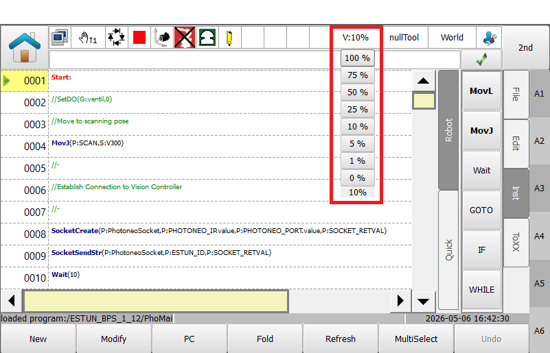
If connection has been established properly you will see Action Request Client and Robot State Server status turn to CONNECTED. At this point the sensor should capture the first scan, localization should start localizing objects and calculating trajectories to first objects in the scene.
If there is a pickable object in the scene and the trajectory for the first object has been received by the robot controller, the robot should start moving towards the first object.
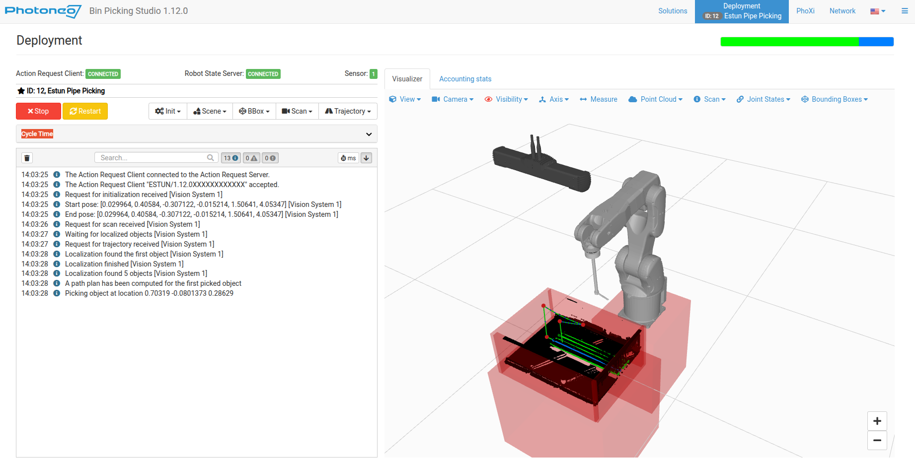
If everything looks fine, keep moving the robot towards the first target and check if the path is correct. At this point if the robot is too far from the object or pushes the object too deep, then make modifications on the Bin Picking Studio Tool Point or Gripping Point pages.
If trajectories look fine, set up your own placing routine and slowly ramp up speed back to 100%
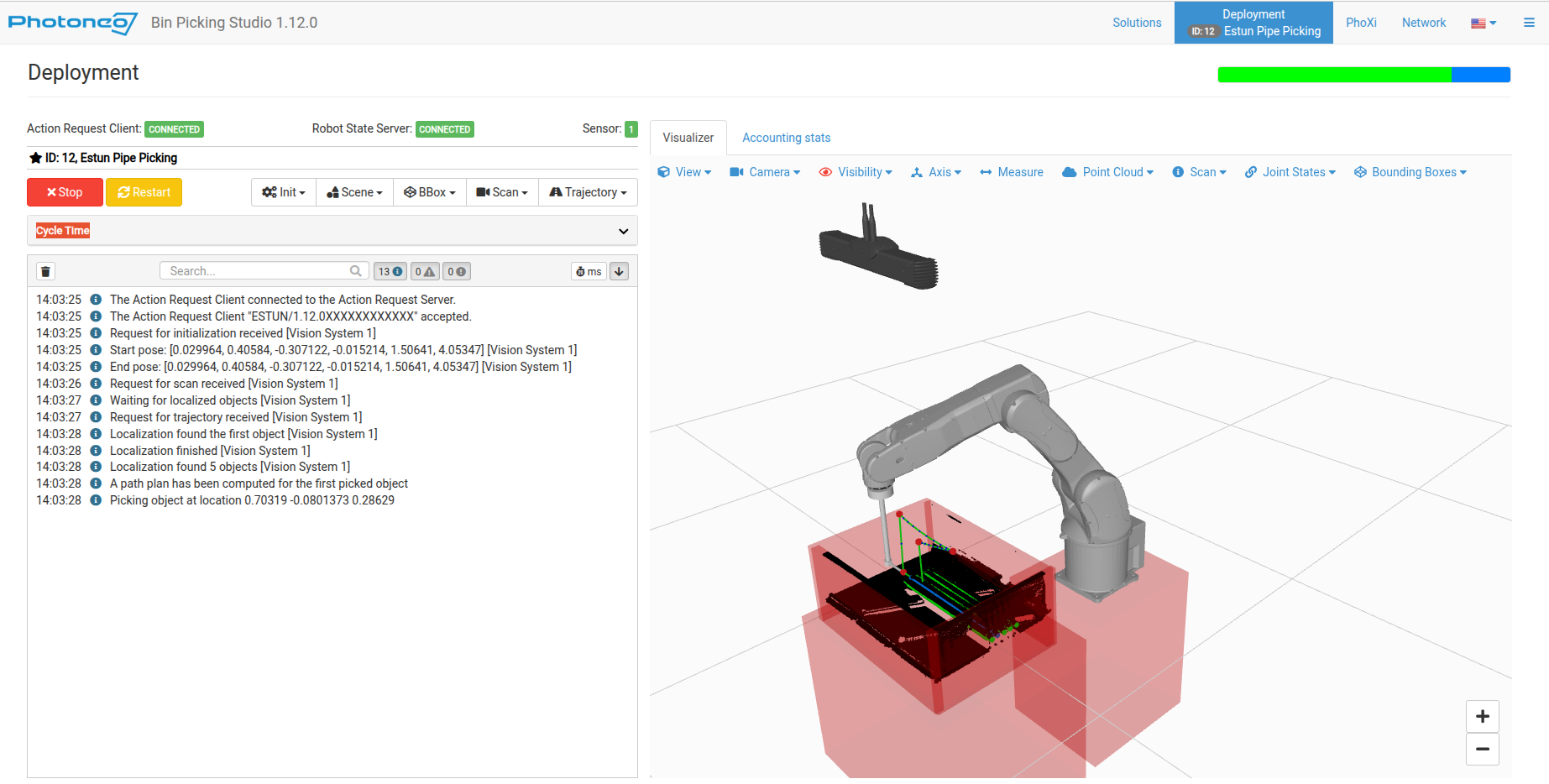
Congratulations, you have successfully deployed Photoneo Estun Interface. You can now focus on improving your application further. Use CheatSheet and Program Templates as your guidelines.