Integration Guide KUKA (KRC)
Note: It is strongly recommended to read the Robot communication overview prior to this integration guide.
Note 2: It is strongly recommended to use the latest version of the integration guide included in the latest available version of the robot module. To download the robot module, please visit the official Photoneo website.
Contents
1 Prerequisites
The Robot module prerequisites:
KRC4 system - v.8.3 or higher
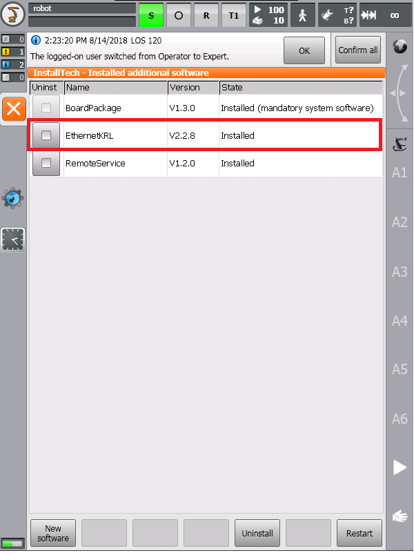
Ethernet KRL Interface - at least v.2.2.8 is required, the highest tested version is v.3.0.3 but all higher versions should be compatible
2 Robot controller setup
2.1 Controller configuration
This guide was originally written using the KRC4 system version 8.3.
2.1.1 Network configuration
Photoneo KUKA Module utilizes TCP/IP communication for transferring data between KRC4 Robot Controller and Bin Picking Studio.
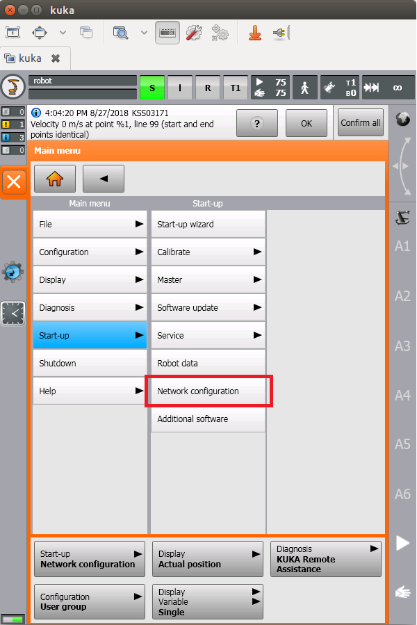
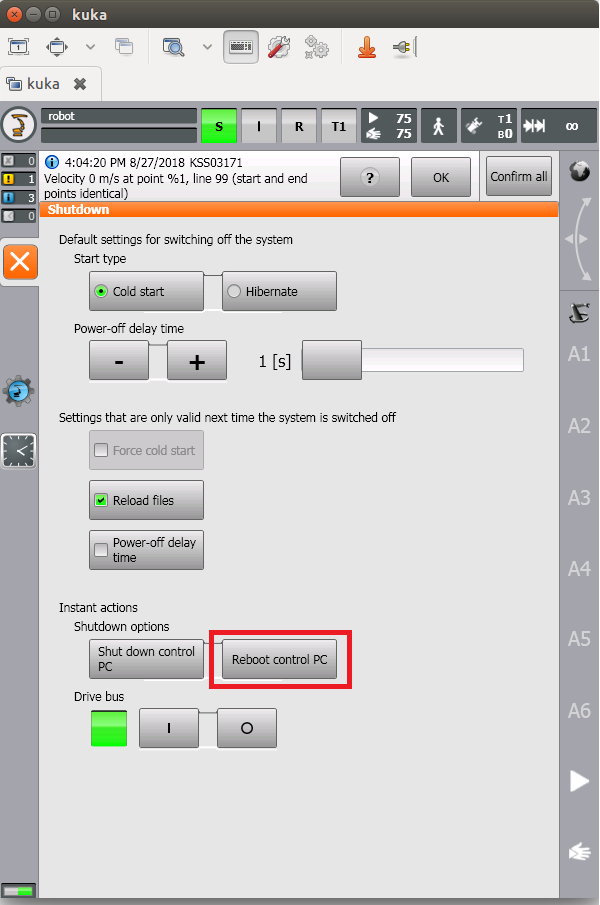
As the first step in commissioning, ensure that the IP address of the KRC4 controller meets your network configuration requirements.

2.2 Robot module installation
The Robot module consists of the following files (folders are bold):
EthernetKRL Config
pho_bp_client.xml
pho_state_server.xml
Photoneo
example_programs
basic_application.src
basic_application.dat
calibration.src
calibration.dat
change_solution.src
change_solution.dat
multi_vision_systems.src
multi_vision_systems.dat
TEACH.src
TEACH.dat
customer_definitions.src
pho_common.src
pho_common.dat
pho_motion.src
pho_motion.dat
pho_state_server.src
pho_state_server.dat
Folder example_programs contains three example programs provided by Photoneo, a program for teaching Start/End positions, and a semi-automatic calibration example program.
2.2.1 Ethernet KRL configuration
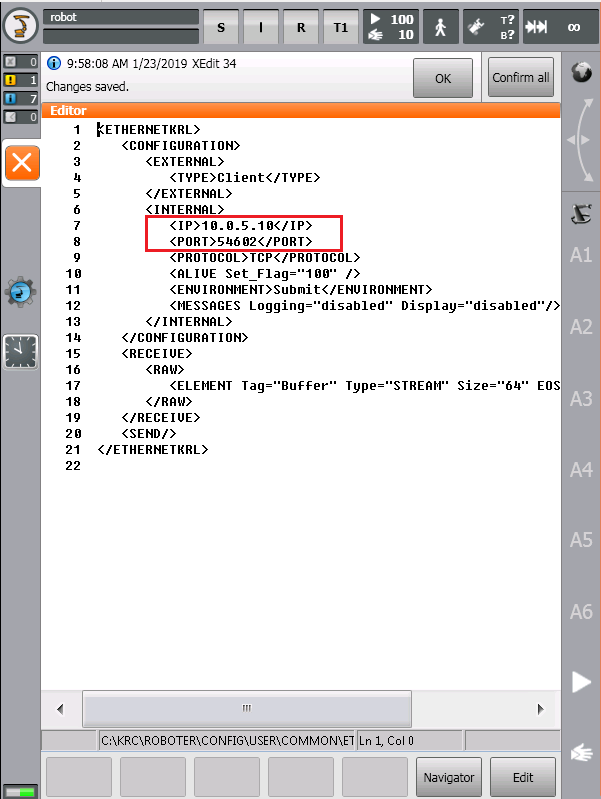
EthernetKRL Config folder contains two XML files - pho_bp_client.xml and pho_state_server.xml.
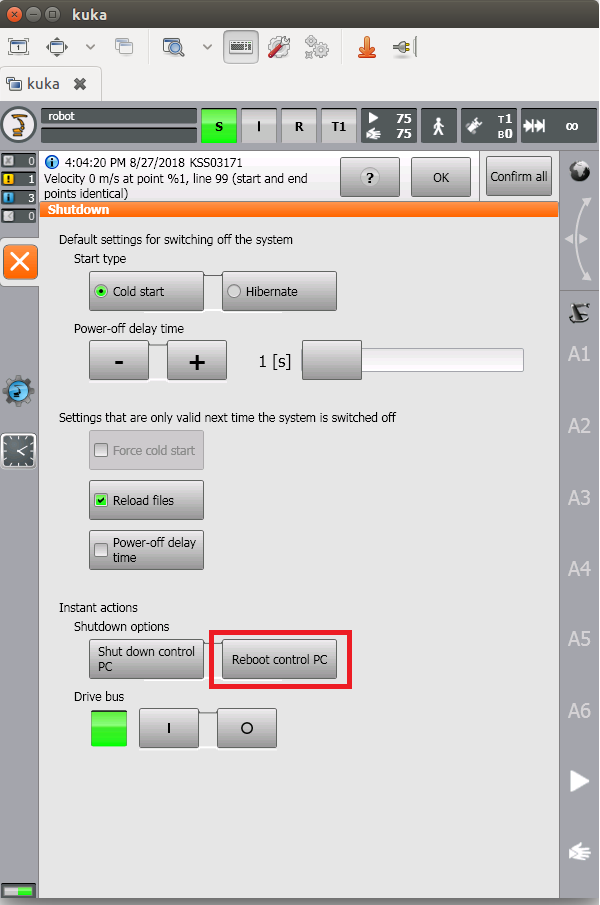
C:\KRC\Roboter\Config\User\Common\EthernetKRL\ as is shown in the figure below:
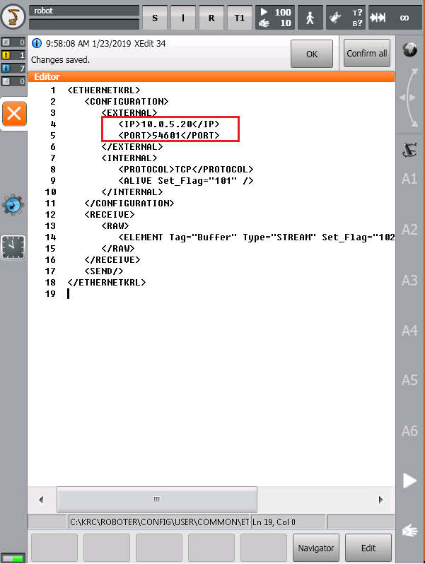
Enter the IP address of the Vision Controller to External IP tag in pho_bp_client.xml as is shown in the figure below.
2.2.2 Loading the Robot module files
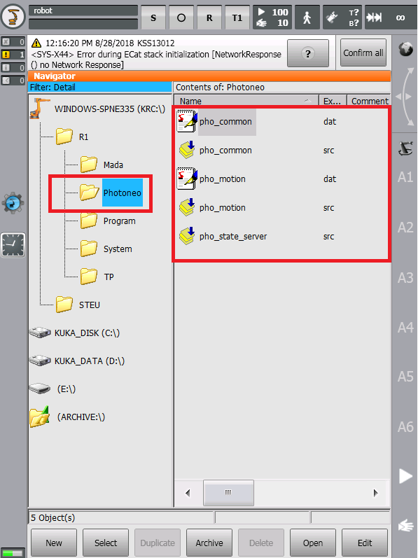
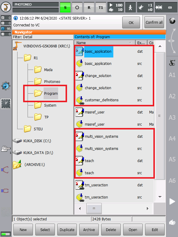
The Photoneo folder contains files that should not be edited by the user (except for the files inside folder example_programs & customer_definitions.src).

2.2.3 Robot State Server configuration
In order to get the Robot State Server up and running, it is necessary to edit the Submit Interpreter program sps.sub in R1/System.
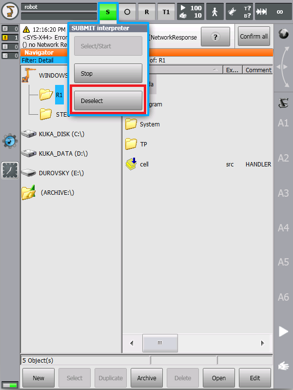
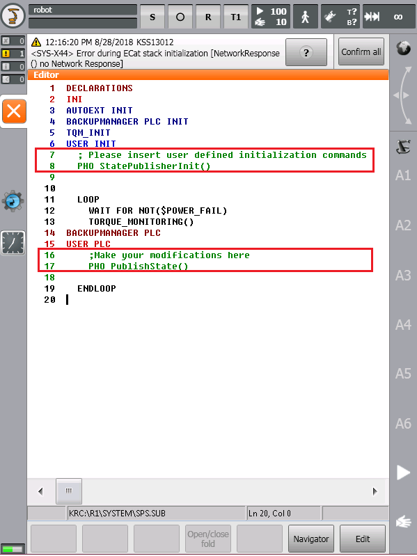
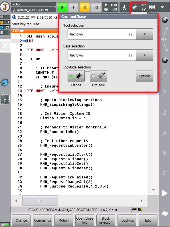
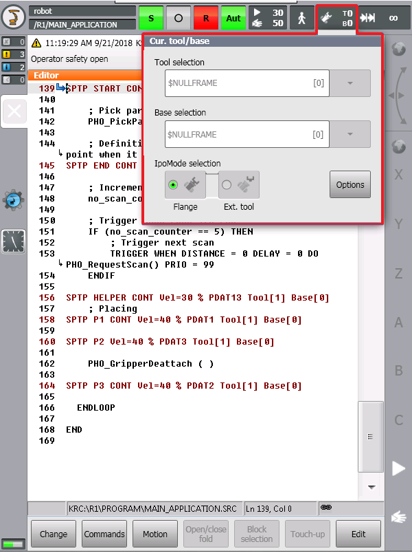
3 Robot module
The Robot module is designed to be easily integrated into existing applications written in KRL language.
3.1 Robotic API
Note: It is strongly recommended to read the Photoneo robotic API prior to this section.
This section describes available API calls provided by the Robot module. These procedures are intended for high-level control of the bin picking application.
3.1.1 Connection procedures
Warning: These procedures are contained in the pho_common API section and must not be edited!
Connection procedure |
Description / Usage |
|---|---|
Connect to Action Request Server PHO_ConnectToVC() |
Description
Function to establish a new connection to the Action Request Server.
Note: The IP of the Action Request Server (vision controller) is configured in pho_bp_client.xml (see 2.2.1 Ethernet KRL configuration). The timeout is not specified which means the default value of 2 seconds is applied. In case the connection is not established before the timeout is reached, an error occurs and the program is halted. Usage
The procedure should be called only once at the beginning of the program. Only after the connection has been established it is possible to send requests.
|
3.1.2 Communication procedures
Note: Please read Action requests for detailed documentation of these procedures.
Warning: These procedures are contained in the pho_common API section and must not be edited!
vision_system_id - global variable. Bin picking requests (except for the Change scene state request) require the vision system ID as an input parameter. It needs to be set to the correct value (ID of the vision system) before sending the request
Bin picking requests
Request |
Input variables |
Output variables |
|---|---|---|
Initialization request PHO_RequestInit(start_pose:IN, end_pose:IN) |
Note: The pose variable has AXIS representation, it is created from the taught position defined as E6POS. Conversion is done using the INVERSE() function. See the following code snippet ( AXIS start_joint_pos, E6POS XSTART1) temp = {A1 0, A2 0, A3 0, A4 0, A5 0, A6 0}
conversion_status = 0
IF FSTART1.TOOL_NO == 0 THEN
$TOOL = $NULLFRAME
ELSE
$TOOL = TOOL_DATA[FSTART1.TOOL_NO]
ENDIF
IF FSTART1.BASE_NO == 0 THEN
$BASE = $NULLFRAME
ELSE
$BASE = BASE_DATA[FSTART1.BASE_NO]
ENDIF
start_joint_pos = INVERSE(XSTART1, temp, conversion_status)
|
|
Scan request PHO_RequestScan() |
|
Note: The response is received by the procedure Wait for scan completion. |
Trajectory request PHO_RequestTrajectory() |
|
Note: The response is received by the procedure Receive trajectory. |
Pick-failed request PHO_RequestPickFailed() |
|
|
Change scene state request INT PHO_RequestEnvChange(env_id:IN) |
|
The error code is accessible in two ways:
|
Calibration requests
Request |
Input variables |
Output variables |
|---|---|---|
Add calibration point request INT PHO_RequestCalibAdd() |
— |
The error code is accessible in two ways:
|
Solution requests
Request |
Input variables |
Output variables |
|---|---|---|
Change solution request PHO_RequestChangeSol()(solution_id:IN) |
|
|
Start solution request INT PHO_RequestStartSol(solution_id:IN) |
|
The error code is accessible in two ways:
|
Stop solution request INT PHO_RequestStopSol() |
— |
The error code is accessible in two ways:
|
Get running solution request INT PHO_RequestGetRunningSol(solution_id:OUT) |
— |
The error code is accessible in two ways:
|
Get available solutions request INT PHO_RequestGetListSol() |
— |
The error code is accessible in two ways:
|
Response receiving procedures
Response receiving procedures |
Input variables |
Output variables |
|---|---|---|
Wait for scan completion INT PHO_WaitForScan() |
— |
The error code is accessible in two ways:
|
Receive trajectory INT PHO_ReceiveTrajectory() |
— |
The error code is accessible in two ways:
|
3.1.3 Bin picking procedures
Note: These procedures are contained in the customer_definitions API section and should be implemented (edited) by the user according to his requirements.
Bin picking procedure |
Description / Usage |
|---|---|
Gripper attach PHO_GripperAttach() |
Description
A user-defined procedure. Typically it is the attach procedure used when the picked object is grasped in the Grasp waypoint.
Usage
It is automatically executed when the waypoint of the grasping method is configured to execute the Attach procedure when it is reached.
|
Gripper detach PHO_GripperDetach() |
Description
A user-defined procedure. Typically it is the detach procedure used when the picked object is placed during the placing routine defined by the robot operator.
Usage
It is automatically executed when the waypoint of the grasping method is configured to execute the Detach procedure when it is reached.
Note: Typically this procedure is not configured to be executed automatically in a waypoint as it should be called during placing which is implemented by the robot operator. |
Gripper user-defined 1 PHO_GripperUser_1() |
Description
A user-defined procedure.
Usage
It is automatically executed when the waypoint of the grasping method is configured to execute the User 1 procedure when it is reached.
|
Gripper user-defined 2 PHO_GripperUser_2() |
Description
A user-defined procedure.
Usage
It is automatically executed when the waypoint of the grasping method is configured to execute the User 2 procedure when it is reached.
|
Gripper user-defined 3 PHO_GripperUser_3() |
Description
A user-defined procedure.
Usage
It is automatically executed when the waypoint of the grasping method is configured to execute the User 3 procedure when it is reached.
|
Set bin picking settings PHO_BinpickingSettings() |
Description
Pre-defined procedure for configuration of the parameters of the individual trajectory segments of the bin picking routine.
Usage
It should be called at the beginning of the main program to set the required settings.
Note: Go to Bin picking routine execution settings to read more about bin picking routine configuration. |
Warning: These procedures are contained in the pho_common API section and must not be edited!
Bin picking procedure |
Description / Usage |
|---|---|
Execute bin picking routine PHO_PickPart() |
Description
Pre-defined procedure for execution of the bin picking routine. This procedure must not be edited directly - to adapt the execution settings please read Bin picking routine execution settings.
Usage
It should be executed after the bin picking trajectory has been received. The robot must be in the start pose when the procedure is executed. At the end of the procedure, the robot will be in the end pose with the picked object attached to the gripper.
Warning: When using multiple start poses (different for multiple vision systems) be extra careful to be in the correct one before executing this procedure. |
3.1.4 List of used registers
Flags
The Robot module utilizes flags $FLAG[101], $FLAG[101], and $FLAG[102]. These flags cannot be used for other purposes.
Flag |
Read / Write access |
Description |
|---|---|---|
|
read-only |
The current state of the connection to the Action Request Server. |
|
read-only |
The current state of the connection to the Robot State Server (whether there is a client connected). |
|
read-only |
Informs about finalized receive operation of the bin picking data. |
3.2 Example programs
The following section contains basic example programs. Each program is intended for a specific bin picking application and it shows the correct usage of the robotic API.
These templates also contain demonstrative error handling. Please note that it serves only as an example and it is up to the user to define suitable routines for dealing with error situations.
Note: When a PLC is used as a high-level controller, the code from the main program can be divided into separate programs and launched directly from the cell.src.
3.2.1 Basic bin picking example
This program is a very basic example of a simple bin picking application. It connects to the vision controller, initializes one vision system, and in a loop, it requests scan, trajectory and executes the received trajectory.
Name: basic_application.src (located in folder example_programs)
DEF basic_application( )
;FOLD INI;%{PE}
BOOL trajectory_ok, scan_ok
E6AXIS temp
AXIS start_joint_pos, end_joint_pos
INT conversion_status, scan_status, trajectory_status
;FOLD BASISTECH INI
GLOBAL INTERRUPT DECL 3 WHEN $STOPMESS == TRUE DO IR_STOPM ( )
INTERRUPT ON 3
BAS (#INITMOV, 0 )
;ENDFOLD (BASISTECH INI)
;FOLD USER INI
;Make your modifications here
;ENDFOLD (USER INI)
;ENDFOLD (INI)
;FOLD PTP HOME Vel= 100 % DEFAULT;%{PE}%MKUKATPBASIS,%CMOVE,%VPTP,%P 1:PTP, 2:HOME, 3:, 5:100, 7:DEFAULT
$BWDSTART = FALSE
PDAT_ACT = PDEFAULT
FDAT_ACT = FHOME
BAS (#PTP_PARAMS, 100 )
$H_POS = XHOME
PTP XHOME
;ENDFOLD
LOOP
; If robot controller has not been connected to vision controller, connect, initialize and trigger first scan
CONTINUE
IF NOT $FLAG[101] THEN
; Ensure that HOME position is reachable from the last placing point (P3 in this case) without collision since transition from P3 to HOME happens when binpicking error occurs
;FOLD PTP HOME Vel= 100 % DEFAULT;%{PE}%MKUKATPBASIS,%CMOVE,%VPTP,%P 1:PTP, 2:HOME, 3:, 5:100, 7:DEFAULT
$BWDSTART = FALSE
PDAT_ACT = PDEFAULT
FDAT_ACT = FHOME
BAS (#PTP_PARAMS, 100 )
$H_POS = XHOME
PTP XHOME
;ENDFOLD
; Apply Binpicking settings
PHO_BinpickingSettings()
; Set Vision System ID (default = 1)
vision_system_id = 1
; Connect to Vision Controller
PHO_ConnectToVc()
;FOLD Convert Start Pose to AXIS representation
temp = {A1 0, A2 0, A3 0, A4 0, A5 0, A6 0}
conversion_status = 0
IF FSTART1.TOOL_NO == 0 THEN
  $TOOL = $NULLFRAME
ELSE
  $TOOL = TOOL_DATA[FSTART1.TOOL_NO]
ENDIF
IF FSTART1.BASE_NO == 0 THEN
  $BASE = $NULLFRAME
ELSE
  $BASE = BASE_DATA[FSTART1.BASE_NO]
ENDIF
start_joint_pos = INVERSE(XSTART1, temp, conversion_status)
;ENDFOLD
;FOLD Convert End Pose to AXIS representation
temp = {A1 0, A2 0, A3 0, A4 0, A5 0, A6 0}
conversion_status = 0
IF FEND1.TOOL_NO == 0 THEN
$TOOL = $NULLFRAME
ELSE
$TOOL = TOOL_DATA[FEND1.TOOL_NO]
ENDIF
IF FEND1.BASE_NO == 0 THEN
$BASE = $NULLFRAME
ELSE
$BASE = BASE_DATA[FEND1.BASE_NO]
ENDIF
end_joint_pos = INVERSE(XEND1, temp, conversion_status)
;ENDFOLD
; Send Initialization Request
PHO_RequestInit(start_joint_pos, end_joint_pos)
; Trigger first scan
PHO_RequestScan()
; Initial Wait
WAIT SEC 10
ENDIF
; Reset trajectory_ok flag
trajectory_ok = FALSE
; Scanning & Planning loop
WHILE trajectory_ok == FALSE
; Wait for first scan
scan_status = PHO_WaitForScan()
IF (scan_status == PHO_OK) THEN
; If Scan OK, request trajectory
PHO_RequestTrajectory()
trajectory_status = PHO_ReceiveTrajectory()
SWITCH trajectory_status
CASE PHO_NOT_INITIALIZED
; Send Initialization Request
PHO_RequestInit(start_joint_pos, end_joint_pos)
; Send Scan Request
PHO_RequestScan()
; Initial Wait
WAIT SEC 10
CASE PHO_SERVICE_ERR
; Send Initialization Request
PHO_RequestInit(start_joint_pos, end_joint_pos)
; Send Scan Request
PHO_RequestScan()
; Initial Wait
WAIT SEC 10
CASE PHO_BAD_DATA
; Send Initialization Request
PHO_RequestInit(start_joint_pos, end_joint_pos)
; Send Scan Request
PHO_RequestScan()
; Initial Wait
WAIT SEC 10
CASE PHO_PLANNING_FAILED
; Send Scan Request
PHO_RequestScan()
CASE PHO_NO_PART_FOUND
; Send Scan Request
PHO_RequestScan()
CASE PHO_OK
; Set blocking flag to true to exit loop
trajectory_ok = TRUE
DEFAULT
LOOP
msgNotify("UNKNOWN TRAJECTORY ERROR: %1", "BP_CLIENT", trajectory_status)
ENDLOOP
ENDSWITCH
ELSE
; Send Initialization Request
PHO_RequestInit(start_joint_pos, end_joint_pos)
; Send Scan Request
PHO_RequestScan()
; Initial Wait
WAIT SEC 10
ENDIF
ENDWHILE
; Move to Start Position
;FOLD SPTP START CONT Vel=30 % PDAT12 Tool[1] Base[0];%{PE}%R 8.3.44,%MKUKATPBASIS,%CSPLINE,%VSPTP_SB,%P 1:SPTP_SB, 2:START, 3:C_DIS, 5:30, 7:PDAT12
SPTP XSTART1 WITH $VEL_AXIS[1]= SVEL_JOINT( 30), $TOOL= STOOL2( FSTART1), $BASE= SBASE( FSTART1.BASE_NO),$IPO_MODE= SIPO_MODE( FSTART1.IPO_FRAME), $LOAD= SLOAD( FSTART1.TOOL_NO), $ACC_AXIS[1]= SACC_JOINT( PPDAT12), $APO= SAPO_PTP( PPDAT12), $GEAR_JERK[1]= SGEAR_JERK( PPDAT12) C_SPL
;ENDFOLD
; Pick part
PHO_PickPart ( )
; Trigger next scan
TRIGGER WHEN DISTANCE = 0 DELAY = 0 DO PHO_RequestScan() PRIO = 99
; Placing
;FOLD SPTP P1 CONT Vel=40 % PDAT1 Tool[1] Base[0];%{PE}%R 8.3.44,%MKUKATPBASIS,%CSPLINE,%VSPTP_SB,%P 1:SPTP_SB, 2:P1, 3:C_DIS, 5:40, 7:PDAT1
SPTP XP1 WITH $VEL_AXIS[1] = SVEL_JOINT( 40), $TOOL = STOOL2( FP1), $BASE = SBASE( FP1.BASE_NO), $IPO_MODE = SIPO_MODE( FP1.IPO_FRAME), $LOAD = SLOAD( FP1.TOOL_NO), $ACC_AXIS[1] = SACC_JOINT( PPDAT1), $APO = SAPO_PTP( PPDAT1), $GEAR_JERK[1] = SGEAR_JERK( PPDAT1) C_SPL
;ENDFOLD
;FOLD SPTP P2 Vel=40 % PDAT3 Tool[1] Base[0];%{PE}%R 8.3.44,%MKUKATPBASIS,%CSPLINE,%VSPTP_SB,%P 1:SPTP_SB, 2:P2, 3:, 5:40, 7:PDAT3
SPTP XP2 WITH $VEL_AXIS[1] = SVEL_JOINT( 40), $TOOL = STOOL2( FP2), $BASE = SBASE( FP2.BASE_NO), $IPO_MODE = SIPO_MODE( FP2.IPO_FRAME), $LOAD = SLOAD( FP2.TOOL_NO), $ACC_AXIS[1] = SACC_JOINT( PPDAT3), $GEAR_JERK[1] = SGEAR_JERK( PPDAT3)
;ENDFOLD
PHO_GripperDetach ( )
;FOLD SPTP P3 CONT Vel=40 % PDAT2 Tool[1] Base[0];%{PE}%R 8.3.44,%MKUKATPBASIS,%CSPLINE,%VSPTP_SB,%P 1:SPTP_SB, 2:P3, 3:C_DIS, 5:40, 7:PDAT2
SPTP XP3 WITH $VEL_AXIS[1] = SVEL_JOINT( 40), $TOOL = STOOL2( FP3), $BASE = SBASE( FP3.BASE_NO), $IPO_MODE = SIPO_MODE( FP3.IPO_FRAME), $LOAD = SLOAD( FP3.TOOL_NO), $ACC_AXIS[1] = SACC_JOINT( PPDAT2), $APO = SAPO_PTP( PPDAT2), $GEAR_JERK[1] = SGEAR_JERK( PPDAT2) C_SPL
;ENDFOLD
ENDLOOP
END
3.2.2 Multiple Vision Systems example
This program is an extension of the basic bin picking example. Instead of one, it initializes two vision systems and switches between them in each cycle.
Name: multi_vision_systems.src (located in folder example_programs)
DEF multi_vision_systems()
  ;FOLD INI;%{PE}
    BOOL trajectory_ok
    E6AXIS temp
    AXIS start_joint_pos1, end_joint_pos1
    AXIS start_joint_pos2, end_joint_pos2
    INT conversion_status, scan_status, trajectory_status

    ;FOLD BASISTECH INI
      GLOBAL INTERRUPT DECL 3 WHEN $STOPMESS == TRUE DO IR_STOPM()
      INTERRUPT ON 3
      BAS (#INITMOV, 0 )
    ;ENDFOLD (BASISTECH INI)
    ;FOLD USER INI
      ;Make your modifications here

    ;ENDFOLD (USER INI)
  ;ENDFOLD (INI)

  ;FOLD PTP HOME Vel=100 % DEFAULT;%{PE}%R 8.3.44,%MKUKATPBASIS,%CMOVE,%VPTP,%P 1:PTP, 2:HOME, 3:, 5:100, 7:DEFAULT
    $BWDSTART=FALSE
    PDAT_ACT=PDEFAULT
    FDAT_ACT=FHOME
    BAS(#PTP_PARAMS,100)
    $H_POS=XHOME
    PTP XHOME
  ;ENDFOLD

  LOOP

    ; If robot controller has not been connected to vision controller, connect, initialize and trigger first scan
    CONTINUE
    IF NOT $FLAG[101] THEN

      ; Ensure that HOME position is reachable from the last placing point without collision since transition from P1 to HOME happens when binpicking error occurs
      ;FOLD PTP HOME Vel=100 % DEFAULT;%{PE}%R 8.3.44,%MKUKATPBASIS,%CMOVE,%VPTP,%P 1:PTP, 2:HOME, 3:, 5:100, 7:DEFAULT
        $BWDSTART=FALSE
        PDAT_ACT=PDEFAULT
        FDAT_ACT=FHOME
        BAS(#PTP_PARAMS,100)
        $H_POS=XHOME
        PTP XHOME
      ;ENDFOLD

      ; Apply Binpicking settings
      PHO_BinpickingSettings()

      ; Connect to Vision Controller
      PHO_ConnectToVc()

      ; Set Vision System ID to 1
      vision_system_id = 1

      ;FOLD Convert Start Pose 1 to AXIS representation
        temp = {A1 0, A2 0, A3 0, A4 0, A5 0, A6 0}
        conversion_status = 0
        IF FSTART1.TOOL_NO == 0 THEN
          $TOOL = $NULLFRAME
        ELSE
          $TOOL = TOOL_DATA[FSTART1.TOOL_NO]
        ENDIF
        IF FSTART1.BASE_NO == 0 THEN
          $BASE = $NULLFRAME
        ELSE
          $BASE = BASE_DATA[FSTART1.BASE_NO]
        ENDIF
        start_joint_pos1 = INVERSE(XSTART1, temp, conversion_status)
      ;ENDFOLD

      ;FOLD Convert End Pose 1 to AXIS representation
        temp = {A1 0, A2 0, A3 0, A4 0, A5 0, A6 0}
        conversion_status = 0
        IF FEND1.TOOL_NO == 0 THEN
          $TOOL = $NULLFRAME
        ELSE
          $TOOL = TOOL_DATA[FEND1.TOOL_NO]
        ENDIF
        IF FEND1.BASE_NO == 0 THEN
          $BASE = $NULLFRAME
        ELSE
          $BASE = BASE_DATA[FEND1.BASE_NO]
        ENDIF
        end_joint_pos1 = INVERSE(XEND1, temp, conversion_status)
      ;ENDFOLD

      ; Send Initialization Request
      PHO_RequestInit(start_joint_pos1, end_joint_pos1)

      ; Set Vision System ID to 2
      vision_system_id = 2

      ;FOLD Convert Start Pose 2 to AXIS representation
        temp = {A1 0, A2 0, A3 0, A4 0, A5 0, A6 0}
        conversion_status = 0
        IF FSTART2.TOOL_NO == 0 THEN
          $TOOL = $NULLFRAME
        ELSE
          $TOOL = TOOL_DATA[FSTART2.TOOL_NO]
        ENDIF
        IF FSTART2.BASE_NO == 0 THEN
          $BASE = $NULLFRAME
        ELSE
          $BASE = BASE_DATA[FSTART2.BASE_NO]
        ENDIF
        start_joint_pos2 = INVERSE(XSTART2, temp, conversion_status)
      ;ENDFOLD

      ;FOLD Convert End Pose 2 to AXIS representation
        temp = {A1 0, A2 0, A3 0, A4 0, A5 0, A6 0}
        conversion_status = 0
        IF FEND2.TOOL_NO == 0 THEN
          $TOOL = $NULLFRAME
        ELSE
          $TOOL = TOOL_DATA[FEND2.TOOL_NO]
        ENDIF
        IF FEND2.BASE_NO == 0 THEN
          $BASE = $NULLFRAME
        ELSE
          $BASE = BASE_DATA[FEND2.BASE_NO]
        ENDIF
        end_joint_pos2 = INVERSE(XEND2, temp, conversion_status)
      ;ENDFOLD

      ; Send Initialization Request
      PHO_RequestInit(start_joint_pos2, end_joint_pos2)

      ; Set Vision System ID to 1
      vision_system_id = 1

      ; Trigger first scan
      PHO_RequestScan()

      ; Initial Wait
      WAIT SEC 10

    ENDIF

    ; Reset trajectory_ok flag
    trajectory_ok = FALSE

    ; Scanning & Planning loop
    WHILE trajectory_ok == FALSE

      ; Wait for first scan
      scan_status = PHO_WaitForScan()

      IF (scan_status == PHO_OK) THEN

        ; If Scan OK, request trajectory
        PHO_RequestTrajectory()
        trajectory_status = PHO_ReceiveTrajectory()

        SWITCH trajectory_status
          CASE PHO_NOT_INITIALIZED

            ; Send Initialization Request
            PHO_RequestInit(start_joint_pos1, end_joint_pos1)
            PHO_RequestInit(start_joint_pos2, end_joint_pos2)

            ; Send Scan Request
            PHO_RequestScan()

            ; Initial Wait
            WAIT SEC 10

          CASE PHO_SERVICE_ERR

            ; Send Initialization Request
            PHO_RequestInit(start_joint_pos1, end_joint_pos1)
            PHO_RequestInit(start_joint_pos2, end_joint_pos2)

            ; Send Scan Request
            PHO_RequestScan()

            ; Initial Wait
            WAIT SEC 10

          CASE PHO_BAD_DATA

            ; Send Initialization Request
            PHO_RequestInit(start_joint_pos1, end_joint_pos1)
            PHO_RequestInit(start_joint_pos2, end_joint_pos2)

            ; Send Scan Request
            PHO_RequestScan()

            ; Initial Wait
            WAIT SEC 10

          CASE PHO_PLANNING_FAILED

            ; Send Scan Request
            PHO_RequestScan()

          CASE PHO_NO_PART_FOUND

            ; Send Scan Request
            PHO_RequestScan()

          CASE PHO_OK

            ; Set blocking flag to true to exit loop
            trajectory_ok = TRUE

          DEFAULT
            LOOP
              msgNotify("UNKNOWN TRAJECTORY ERROR: %1", "BP_CLIENT", trajectory_status)
            ENDLOOP

        ENDSWITCH
      ELSE

        ; Send Initialization Request
        PHO_RequestInit(start_joint_pos1, end_joint_pos1)
        PHO_RequestInit(start_joint_pos2, end_joint_pos2)

        ; Send Scan Request
        PHO_RequestScan()

        ; Initial Wait
        WAIT SEC 10

      ENDIF

    ENDWHILE


    IF (vision_system_id == 1) THEN
      ; Move to Start Position 1
      ;FOLD SPTP START1 CONT Vel=30 % PDAT2 Tool[1] Base[0];%{PE}%R 8.3.44,%MKUKATPBASIS,%CSPLINE,%VSPTP_SB,%P 1:SPTP_SB, 2:START1, 3:C_DIS, 5:30, 7:PDAT2
        SPTP XSTART1 WITH $VEL_AXIS[1]= SVEL_JOINT( 30), $TOOL= STOOL2( FSTART1), $BASE= SBASE( FSTART1.BASE_NO),$IPO_MODE= SIPO_MODE( FSTART1.IPO_FRAME), $LOAD= SLOAD( FSTART1.TOOL_NO), $ACC_AXIS[1]= SACC_JOINT( PPDAT2), $APO= SAPO_PTP( PPDAT2), $GEAR_JERK[1]= SGEAR_JERK( PPDAT2) C_SPL
      ;ENDFOLD
    ELSE
      ; Move to Start Position 2
      ;FOLD SPTP START2 CONT Vel=30 % PDAT2 Tool[1] Base[0];%{PE}%R 8.3.44,%MKUKATPBASIS,%CSPLINE,%VSPTP_SB,%P 1:SPTP_SB, 2:START2, 3:C_DIS, 5:30, 7:PDAT2
        SPTP XSTART2 WITH $VEL_AXIS[1]= SVEL_JOINT( 30), $TOOL= STOOL2( FSTART2), $BASE= SBASE( FSTART2.BASE_NO),$IPO_MODE= SIPO_MODE( FSTART2.IPO_FRAME), $LOAD= SLOAD( FSTART2.TOOL_NO), $ACC_AXIS[1]= SACC_JOINT( PPDAT2), $APO= SAPO_PTP( PPDAT2), $GEAR_JERK[1]= SGEAR_JERK( PPDAT2) C_SPL
      ;ENDFOLD
    ENDIF

    ; Pick part
    PHO_PickPart ( )

    ; Move out from scanning volume
    ;FOLD SPTP HOME CONT Vel=100 % PDAT3 Tool[1] Base[0];%{PE}%R 8.3.44,%MKUKATPBASIS,%CSPLINE,%VSPTP_SB,%P 1:SPTP_SB, 2:HOME, 3:C_DIS, 5:100, 7:PDAT3
      SPTP XHOME WITH $VEL_AXIS[1]= SVEL_JOINT( 100), $TOOL= STOOL2( FHOME), $BASE= SBASE( FHOME.BASE_NO),$IPO_MODE= SIPO_MODE( FHOME.IPO_FRAME), $LOAD= SLOAD( FHOME.TOOL_NO), $ACC_AXIS[1]= SACC_JOINT( PPDAT3), $APO= SAPO_PTP( PPDAT3), $GEAR_JERK[1]= SGEAR_JERK( PPDAT3) C_SPL
    ;ENDFOLD

    ; Switch Vision System IDs
    IF (vision_system_id == 1) THEN
      vision_system_id = 2
    ELSE
      vision_system_id = 1
    ENDIF

    ; Trigger next scan
    TRIGGER WHEN DISTANCE = 0 DELAY = 0 DO PHO_RequestScan() PRIO = 99

    ; Placing - Use Vision System ID to differentiate between placing positions
    ;FOLD SPTP P1 Vel=30 % PDAT1 Tool[1] Base[0];%{PE}%R 8.3.44,%MKUKATPBASIS,%CSPLINE,%VSPTP_SB,%P 1:SPTP_SB, 2:P1, 3:, 5:30, 7:PDAT1
      SPTP XP1 WITH $VEL_AXIS[1]= SVEL_JOINT( 30), $TOOL= STOOL2( FP1), $BASE= SBASE( FP1.BASE_NO),$IPO_MODE= SIPO_MODE( FP1.IPO_FRAME), $LOAD= SLOAD( FP1.TOOL_NO), $ACC_AXIS[1]= SACC_JOINT( PPDAT1), $GEAR_JERK[1]= SGEAR_JERK( PPDAT1)
    ;ENDFOLD

    PHO_GripperDetach()

  ENDLOOP

END
3.2.3 Change solution example
A single robotic cell can take part in several production processes. Handling of multiple parts concurrently is done by using multiple vision systems in one solution. When completely changing the production process it is more suitable to have separate dedicated solutions that can be deployed directly from the robot.
This program is an extension of the basic bin picking example. After a defined number of bin picking cycles, it sends a request to change the deployed solution.
Name: change_solution.src (located in folder example_programs)
DEF change_solution( )
  ;FOLD INI;%{PE}
    BOOL trajectory_ok
    E6AXIS temp
    AXIS start_joint_pos, end_joint_pos
    INT conversion_status, scan_status, trajectory_status
    INT solution_id, MAX_PICKS, pick_counter
    INT solutionID1, solutionID2
    bool initialized

    ;FOLD BASISTECH INI
      GLOBAL INTERRUPT DECL 3 WHEN $STOPMESS == TRUE DO IR_STOPM ( )
      INTERRUPT ON 3
      BAS (#INITMOV, 0 )
    ;ENDFOLD (BASISTECH INI)
    ;FOLD USER INI
      ;Make your modifications here

    ;ENDFOLD (USER INI)
  ;ENDFOLD (INI)

  ;FOLD PTP HOME Vel=100 % DEFAULT;%{PE}%R 8.3.44,%MKUKATPBASIS,%CMOVE,%VPTP,%P 1:PTP, 2:HOME, 3:, 5:100, 7:DEFAULT
    $BWDSTART=FALSE
    PDAT_ACT=PDEFAULT
    FDAT_ACT=FHOME
    BAS(#PTP_PARAMS,100)
    $H_POS=XHOME
    PTP XHOME
  ;ENDFOLD

  ; Define Solution IDs
  solutionID1 = 3
  solutionID2 = 1

  ; Set Current Solution ID
  solution_id = solutionID1

  ; Maximum count of picked parts to change solution
  MAX_PICKS = 10
  initialized=false
  LOOP

    ; If robot controller has not been connected to vision controller, connect, initialize and trigger first scan
    CONTINUE
    IF NOT $FLAG[101] OR not initialized THEN

      ; Ensure that HOME position is reachable from the last placing point without collision since transition from P1 to HOME happens when binpicking error occurs
      ;FOLD PTP HOME Vel=100 % DEFAULT;%{PE}%R 8.3.44,%MKUKATPBASIS,%CMOVE,%VPTP,%P 1:PTP, 2:HOME, 3:, 5:100, 7:DEFAULT
        $BWDSTART=FALSE
        PDAT_ACT=PDEFAULT
        FDAT_ACT=FHOME
        BAS(#PTP_PARAMS,100)
        $H_POS=XHOME
        PTP XHOME
      ;ENDFOLD

      ; Apply Binpicking settings
      PHO_BinpickingSettings()

      ; Initialize picked parts counter
      pick_counter = 0

      ; Connect to Vision Controller
      PHO_ConnectToVc()

      ; Set Vision System ID
      vision_system_id = 1

      ; Set Start/End pose according to current solution
      IF (solution_id == solutionID1) THEN
        ;FOLD Convert Start Pose 1 to AXIS representation
          temp = {A1 0, A2 0, A3 0, A4 0, A5 0, A6 0}
          conversion_status = 0
          IF FSTART1.TOOL_NO == 0 THEN
            $TOOL = $NULLFRAME
          ELSE
            $TOOL = TOOL_DATA[FSTART1.TOOL_NO]
          ENDIF
          IF FSTART1.BASE_NO == 0 THEN
            $BASE = $NULLFRAME
          ELSE
            $BASE = BASE_DATA[FSTART1.BASE_NO]
          ENDIF
          start_joint_pos = INVERSE(XSTART1, temp, conversion_status)
        ;ENDFOLD

        ;FOLD Convert End Pose 1 to AXIS representation
          temp = {A1 0, A2 0, A3 0, A4 0, A5 0, A6 0}
          conversion_status = 0
          IF FEND1.TOOL_NO == 0 THEN
            $TOOL = $NULLFRAME
          ELSE
            $TOOL = TOOL_DATA[FEND1.TOOL_NO]
          ENDIF
          IF FEND1.BASE_NO == 0 THEN
            $BASE = $NULLFRAME
          ELSE
            $BASE = BASE_DATA[FEND1.BASE_NO]
          ENDIF
          end_joint_pos = INVERSE(XEND1, temp, conversion_status)
        ;ENDFOLD
      ELSE
        ;FOLD Convert Start Pose 2 to AXIS representation
          temp = {A1 0, A2 0, A3 0, A4 0, A5 0, A6 0}
          conversion_status = 0
          IF FSTART2.TOOL_NO == 0 THEN
            $TOOL = $NULLFRAME
          ELSE
            $TOOL = TOOL_DATA[FSTART2.TOOL_NO]
          ENDIF
          IF FSTART2.BASE_NO == 0 THEN
            $BASE = $NULLFRAME
          ELSE
            $BASE = BASE_DATA[FSTART2.BASE_NO]
          ENDIF
          start_joint_pos = INVERSE(XSTART2, temp, conversion_status)
        ;ENDFOLD

        ;FOLD Convert End Pose 2 to AXIS representation
          temp = {A1 0, A2 0, A3 0, A4 0, A5 0, A6 0}
          conversion_status = 0
          IF FEND2.TOOL_NO == 0 THEN
            $TOOL = $NULLFRAME
          ELSE
            $TOOL = TOOL_DATA[FEND2.TOOL_NO]
          ENDIF
          IF FEND2.BASE_NO == 0 THEN
            $BASE = $NULLFRAME
          ELSE
            $BASE = BASE_DATA[FEND2.BASE_NO]
          ENDIF
          end_joint_pos = INVERSE(XEND2, temp, conversion_status)
        ;ENDFOLD
      ENDIF

      ; Send Initialization Request
      PHO_RequestInit(start_joint_pos, end_joint_pos)
      initialized=TRUE
      ; Trigger first scan
      PHO_RequestScan()

      ; Initial Wait
      WAIT SEC 10

    ENDIF

    ; Reset trajectory_ok flag
    trajectory_ok = FALSE

    ; Scanning & Planning loop
    WHILE trajectory_ok == FALSE

      ; Wait for first scan
      scan_status = PHO_WaitForScan()

      IF (scan_status == PHO_OK) THEN

        ; If Scan OK, request trajectory
        PHO_RequestTrajectory()
        trajectory_status = PHO_ReceiveTrajectory()

        SWITCH trajectory_status
          CASE PHO_NOT_INITIALIZED

            ; Send Initialization Request
            PHO_RequestInit(start_joint_pos, end_joint_pos)

            ; Send Scan Request
            PHO_RequestScan()

            ; Initial Wait
            WAIT SEC 10

          CASE PHO_SERVICE_ERR

            ; Send Initialization Request
            PHO_RequestInit(start_joint_pos, end_joint_pos)

            ; Send Scan Request
            PHO_RequestScan()

            ; Initial Wait
            WAIT SEC 10

          CASE PHO_BAD_DATA

            ; Send Initialization Request
            PHO_RequestInit(start_joint_pos, end_joint_pos)

            ; Send Scan Request
            PHO_RequestScan()

            ; Initial Wait
            WAIT SEC 10

          CASE PHO_PLANNING_FAILED

            ; Send Scan Request
            PHO_RequestScan()

          CASE PHO_NO_PART_FOUND

            ; Send Scan Request
            PHO_RequestScan()

          CASE PHO_OK

            ; Set blocking flag to true to exit loop
            trajectory_ok = TRUE

          DEFAULT
            LOOP
              msgNotify("UNKNOWN TRAJECTORY ERROR: %1", "BP_CLIENT", trajectory_status)
            ENDLOOP

        ENDSWITCH
      ELSE

        ; Send Initialization Request
        PHO_RequestInit(start_joint_pos, end_joint_pos)

        ; Send Scan Request
        PHO_RequestScan()

        ; Initial Wait
        WAIT SEC 10

      ENDIF

    ENDWHILE


    IF (solution_id == solutionID1) THEN
      ; Move to Start Position 1
      ;FOLD SPTP START1 CONT Vel=30 % PDAT2 Tool[1] Base[0];%{PE}%R 8.3.44,%MKUKATPBASIS,%CSPLINE,%VSPTP_SB,%P 1:SPTP_SB, 2:START1, 3:C_DIS, 5:30, 7:PDAT2
        SPTP XSTART1 WITH $VEL_AXIS[1]= SVEL_JOINT( 30), $TOOL= STOOL2( FSTART1), $BASE= SBASE( FSTART1.BASE_NO),$IPO_MODE= SIPO_MODE( FSTART1.IPO_FRAME), $LOAD= SLOAD( FSTART1.TOOL_NO), $ACC_AXIS[1]= SACC_JOINT( PPDAT2), $APO= SAPO_PTP( PPDAT2), $GEAR_JERK[1]= SGEAR_JERK( PPDAT2) C_SPL
      ;ENDFOLD
    ELSE
      ; Move to Start Position 2
      ;FOLD SPTP START2 CONT Vel=30 % PDAT2 Tool[1] Base[0];%{PE}%R 8.3.44,%MKUKATPBASIS,%CSPLINE,%VSPTP_SB,%P 1:SPTP_SB, 2:START2, 3:C_DIS, 5:30, 7:PDAT2
        SPTP XSTART2 WITH $VEL_AXIS[1]= SVEL_JOINT( 30), $TOOL= STOOL2( FSTART2), $BASE= SBASE( FSTART2.BASE_NO),$IPO_MODE= SIPO_MODE( FSTART2.IPO_FRAME), $LOAD= SLOAD( FSTART2.TOOL_NO), $ACC_AXIS[1]= SACC_JOINT( PPDAT2), $APO= SAPO_PTP( PPDAT2), $GEAR_JERK[1]= SGEAR_JERK( PPDAT2) C_SPL
      ;ENDFOLD
    ENDIF

    ; Pick part
    PHO_PickPart ( )

    ; Increment picked parts counter
    pick_counter = pick_counter + 1

    ; Move out from scanning volume
    ;FOLD SPTP HOME CONT Vel=100 % PDAT3 Tool[1] Base[0];%{PE}%R 8.3.44,%MKUKATPBASIS,%CSPLINE,%VSPTP_SB,%P 1:SPTP_SB, 2:HOME, 3:C_DIS, 5:100, 7:PDAT3
      SPTP XHOME WITH $VEL_AXIS[1]= SVEL_JOINT( 100), $TOOL= STOOL2( FHOME), $BASE= SBASE( FHOME.BASE_NO),$IPO_MODE= SIPO_MODE( FHOME.IPO_FRAME), $LOAD= SLOAD( FHOME.TOOL_NO), $ACC_AXIS[1]= SACC_JOINT( PPDAT3), $APO= SAPO_PTP( PPDAT3), $GEAR_JERK[1]= SGEAR_JERK( PPDAT3) C_SPL
    ;ENDFOLD

    IF (pick_counter < MAX_PICKS) THEN
      ; Trigger next scan
      TRIGGER WHEN DISTANCE = 0 DELAY = 0 DO PHO_RequestScan() PRIO = 99

      ; Placing - Use Vision System ID to differentiate between placing positions
      ;FOLD SPTP P1 Vel=30 % PDAT1 Tool[1] Base[0];%{PE}%R 8.3.44,%MKUKATPBASIS,%CSPLINE,%VSPTP_SB,%P 1:SPTP_SB, 2:P1, 3:, 5:30, 7:PDAT1
        SPTP XP1 WITH $VEL_AXIS[1]= SVEL_JOINT( 30), $TOOL= STOOL2( FP1), $BASE= SBASE( FP1.BASE_NO),$IPO_MODE= SIPO_MODE( FP1.IPO_FRAME), $LOAD= SLOAD( FP1.TOOL_NO), $ACC_AXIS[1]= SACC_JOINT( PPDAT1), $GEAR_JERK[1]= SGEAR_JERK( PPDAT1)
      ;ENDFOLD

      PHO_GripperDetach()
    ELSE
      ; Reset picked parts counter
      pick_counter = 0

      ; Placing - Use Solution ID to differentiate between placing positions
      ;FOLD SPTP P1 Vel=30 % PDAT1 Tool[1] Base[0];%{PE}%R 8.3.44,%MKUKATPBASIS,%CSPLINE,%VSPTP_SB,%P 1:SPTP_SB, 2:P1, 3:, 5:30, 7:PDAT1
        SPTP XP1 WITH $VEL_AXIS[1]= SVEL_JOINT( 30), $TOOL= STOOL2( FP1), $BASE= SBASE( FP1.BASE_NO),$IPO_MODE= SIPO_MODE( FP1.IPO_FRAME), $LOAD= SLOAD( FP1.TOOL_NO), $ACC_AXIS[1]= SACC_JOINT( PPDAT1), $GEAR_JERK[1]= SGEAR_JERK( PPDAT1)
      ;ENDFOLD

      PHO_GripperDetach()

      ; Change solution
      IF (solution_id == solutionID1) THEN
        solution_id = solutionID2
      ELSE
        solution_id = solutionID1
      ENDIF
      PHO_RequestChangeSol(solution_id)
      initialized=FALSE


    ENDIF

  ENDLOOP

END
3.2.4 Calibration example
This program is a template for semi-automatic calibration.
Before running the program:
teach the individual calibration poses
start the calibration in the Bin Picking Studio
Now you can start the program. It will move to individual calibration poses and send the Add calibration point request when it reaches them. Once all the calibration points are successfully added, the program ends. If you are satisfied with the calibration result, save it in the Bin Picking Studio.
Name: calibration.src (located in folder example_programs)
DEF calibration( )
   ;FOLD INI;%{PE}
      INT status

      ;FOLD BASISTECH INI
         GLOBAL INTERRUPT DECL 3 WHEN $STOPMESS == TRUE DO IR_STOPM ( )
         INTERRUPT ON 3
         BAS (#INITMOV, 0 )
      ;ENDFOLD (BASISTECH INI)
      ;FOLD USER INI
         ;Make your modifications here

      ;ENDFOLD (USER INI)
   ;ENDFOLD (INI)

   ;FOLD PTP HOME Vel=100 % DEFAULT;%{PE}%R 8.3.44,%MKUKATPBASIS,%CMOVE,%VPTP,%P 1:PTP, 2:HOME, 3:, 5:100, 7:DEFAULT
      $BWDSTART=FALSE
      PDAT_ACT=PDEFAULT
      FDAT_ACT=FHOME
      BAS(#PTP_PARAMS,100)
      $H_POS=XHOME
      PTP XHOME
   ;ENDFOLD

   ; Connect to VC if robot controller has not been connected to VC yet
   CONTINUE
   IF NOT $FLAG[101] THEN

      ; Move to Home Position
      ;FOLD PTP HOME Vel=100 % DEFAULT;%{PE}%R 8.3.44,%MKUKATPBASIS,%CMOVE,%VPTP,%P 1:PTP, 2:HOME, 3:, 5:100, 7:DEFAULT
         $BWDSTART=FALSE
         PDAT_ACT=PDEFAULT
         FDAT_ACT=FHOME
         BAS(#PTP_PARAMS,100)
         $H_POS=XHOME
         PTP XHOME
      ;ENDFOLD

      ; Apply Binpicking settings
      PHO_BinpickingSettings()

      ; Connect to Vision Controller
      PHO_ConnectToVc()

   ENDIF

   ; 1. Calibration waypoint
   ;FOLD SPTP P1 Vel=100 % PDAT1 Tool[1] Base[0];%{PE}%R 8.3.44,%MKUKATPBASIS,%CSPLINE,%VSPTP_SB,%P 1:SPTP_SB, 2:P1, 3:, 5:100, 7:PDAT1
      SPTP XP1 WITH $VEL_AXIS[1]= SVEL_JOINT( 100), $TOOL= STOOL2( FP1), $BASE= SBASE( FP1.BASE_NO),$IPO_MODE= SIPO_MODE( FP1.IPO_FRAME), $LOAD= SLOAD( FP1.TOOL_NO), $ACC_AXIS[1]= SACC_JOINT( PPDAT1), $GEAR_JERK[1]= SGEAR_JERK( PPDAT1)
   ;ENDFOLD
   ;Wait 1 sec to ensure that the robot is in the position
   WAIT SEC 1
   status=PHO_RequestCalibAdd()
   IF status <> 0 THEN
      LOOP
         msgQuit("Failed to add calibration point %1", "BP CLIENT",error_code)
      ENDLOOP
   ENDIF

   ; 2. Calibration waypoint
   ;FOLD SPTP P2 Vel=100 % PDAT1 Tool[1] Base[0];%{PE}%R 8.3.44,%MKUKATPBASIS,%CSPLINE,%VSPTP_SB,%P 1:SPTP_SB, 2:P2, 3:, 5:100, 7:PDAT1
      SPTP XP2 WITH $VEL_AXIS[1]= SVEL_JOINT( 100), $TOOL= STOOL2( FP2), $BASE= SBASE( FP2.BASE_NO),$IPO_MODE= SIPO_MODE( FP2.IPO_FRAME), $LOAD= SLOAD( FP2.TOOL_NO), $ACC_AXIS[1]= SACC_JOINT( PPDAT1), $GEAR_JERK[1]= SGEAR_JERK( PPDAT1)
   ;ENDFOLD
   ;Wait 1 sec to ensure that the robot is in the position
   WAIT SEC 1
   status=PHO_RequestCalibAdd()
   IF status <> 0 THEN
      LOOP
         msgQuit("Failed to add calibration point %1", "BP CLIENT",error_code)
      ENDLOOP
   ENDIF

   ; 3 Calibration waypoint
   ;FOLD SPTP P3 Vel=100 % PDAT1 Tool[1] Base[0];%{PE}%R 8.3.44,%MKUKATPBASIS,%CSPLINE,%VSPTP_SB,%P 1:SPTP_SB, 2:P3, 3:, 5:100, 7:PDAT1
      SPTP XP3 WITH $VEL_AXIS[1]= SVEL_JOINT( 100), $TOOL= STOOL2( FP3), $BASE= SBASE( FP3.BASE_NO),$IPO_MODE= SIPO_MODE( FP3.IPO_FRAME), $LOAD= SLOAD( FP3.TOOL_NO), $ACC_AXIS[1]= SACC_JOINT( PPDAT1), $GEAR_JERK[1]= SGEAR_JERK( PPDAT1)
   ;ENDFOLD
   ;Wait 1 sec to ensure that the robot is in the position
   WAIT SEC 1
   status=PHO_RequestCalibAdd()
   IF status <> 0 THEN
      LOOP
         msgQuit("Failed to add calibration point %1", "BP CLIENT",error_code)
      ENDLOOP
   ENDIF

   ; 4. Calibration waypoint
   ;FOLD SPTP P4 Vel=100 % PDAT1 Tool[1] Base[0];%{PE}%R 8.3.44,%MKUKATPBASIS,%CSPLINE,%VSPTP_SB,%P 1:SPTP_SB, 2:P4, 3:, 5:100, 7:PDAT1
      SPTP XP4 WITH $VEL_AXIS[1]= SVEL_JOINT( 100), $TOOL= STOOL2( FP4), $BASE= SBASE( FP4.BASE_NO),$IPO_MODE= SIPO_MODE( FP4.IPO_FRAME), $LOAD= SLOAD( FP4.TOOL_NO), $ACC_AXIS[1]= SACC_JOINT( PPDAT1), $GEAR_JERK[1]= SGEAR_JERK( PPDAT1)
   ;ENDFOLD
   ;Wait 1 sec to ensure that the robot is in the position
   WAIT SEC 1
   status=PHO_RequestCalibAdd()
   IF status <> 0 THEN
      LOOP
         msgQuit("Failed to add calibration point %1", "BP CLIENT",error_code)
      ENDLOOP
   ENDIF

   ; 5. Calibration waypoint
   ;FOLD SPTP P5 Vel=100 % PDAT1 Tool[1] Base[0];%{PE}%R 8.3.44,%MKUKATPBASIS,%CSPLINE,%VSPTP_SB,%P 1:SPTP_SB, 2:P5, 3:, 5:100, 7:PDAT1
      SPTP XP5 WITH $VEL_AXIS[1]= SVEL_JOINT( 100), $TOOL= STOOL2( FP5), $BASE= SBASE( FP5.BASE_NO),$IPO_MODE= SIPO_MODE( FP5.IPO_FRAME), $LOAD= SLOAD( FP5.TOOL_NO), $ACC_AXIS[1]= SACC_JOINT( PPDAT1), $GEAR_JERK[1]= SGEAR_JERK( PPDAT1)
   ;ENDFOLD
   ;Wait 1 sec to ensure that the robot is in the position
   WAIT SEC 1
   status=PHO_RequestCalibAdd()
   IF status <> 0 THEN
      LOOP
         msgQuit("Failed to add calibration point %1", "BP CLIENT",error_code)
      ENDLOOP
   ENDIF

   ; 6. Calibration waypoint
   ;FOLD SPTP P6 Vel=100 % PDAT1 Tool[1] Base[0];%{PE}%R 8.3.44,%MKUKATPBASIS,%CSPLINE,%VSPTP_SB,%P 1:SPTP_SB, 2:P6, 3:, 5:100, 7:PDAT1
      SPTP XP6 WITH $VEL_AXIS[1]= SVEL_JOINT( 100), $TOOL= STOOL2( FP6), $BASE= SBASE( FP6.BASE_NO),$IPO_MODE= SIPO_MODE( FP6.IPO_FRAME), $LOAD= SLOAD( FP6.TOOL_NO), $ACC_AXIS[1]= SACC_JOINT( PPDAT1), $GEAR_JERK[1]= SGEAR_JERK( PPDAT1)
   ;ENDFOLD
   ;Wait 1 sec to ensure that the robot is in the position
   WAIT SEC 1
   status=PHO_RequestCalibAdd()
   IF status <> 0 THEN
      LOOP
         msgQuit("Failed to add calibration point %1", "BP CLIENT",error_code)
      ENDLOOP
   ENDIF

   ; 7. Calibration waypoint
   ;FOLD SPTP P7 Vel=100 % PDAT1 Tool[1] Base[0];%{PE}%R 8.3.44,%MKUKATPBASIS,%CSPLINE,%VSPTP_SB,%P 1:SPTP_SB, 2:P7, 3:, 5:100, 7:PDAT1
      SPTP XP7 WITH $VEL_AXIS[1]= SVEL_JOINT( 100), $TOOL= STOOL2( FP7), $BASE= SBASE( FP7.BASE_NO),$IPO_MODE= SIPO_MODE( FP7.IPO_FRAME), $LOAD= SLOAD( FP7.TOOL_NO), $ACC_AXIS[1]= SACC_JOINT( PPDAT1), $GEAR_JERK[1]= SGEAR_JERK( PPDAT1)
   ;ENDFOLD
   ;Wait 1 sec to ensure that the robot is in the position
   WAIT SEC 1
   status=PHO_RequestCalibAdd()
   IF status <> 0 THEN
      LOOP
         msgQuit("Failed to add calibration point %1", "BP CLIENT",error_code)
      ENDLOOP
   ENDIF

   ; 8. Calibration waypoint
   ;FOLD SPTP P8 Vel=100 % PDAT1 Tool[1] Base[0];%{PE}%R 8.3.44,%MKUKATPBASIS,%CSPLINE,%VSPTP_SB,%P 1:SPTP_SB, 2:P8, 3:, 5:100, 7:PDAT1
      SPTP XP8 WITH $VEL_AXIS[1]= SVEL_JOINT( 100), $TOOL= STOOL2( FP8), $BASE= SBASE( FP8.BASE_NO),$IPO_MODE= SIPO_MODE( FP8.IPO_FRAME), $LOAD= SLOAD( FP8.TOOL_NO), $ACC_AXIS[1]= SACC_JOINT( PPDAT1), $GEAR_JERK[1]= SGEAR_JERK( PPDAT1)
   ;ENDFOLD
   ;Wait 1 sec to ensure that the robot is in the position
   WAIT SEC 1
   status=PHO_RequestCalibAdd()
   IF status <> 0 THEN
      LOOP
         msgQuit("Failed to add calibration point %1", "BP CLIENT",error_code)
      ENDLOOP
   ENDIF

   ; 9. Calibration waypoint
   ;FOLD SPTP P9 Vel=100 % PDAT1 Tool[1] Base[0];%{PE}%R 8.3.44,%MKUKATPBASIS,%CSPLINE,%VSPTP_SB,%P 1:SPTP_SB, 2:P9, 3:, 5:100, 7:PDAT1
      SPTP XP9 WITH $VEL_AXIS[1]= SVEL_JOINT( 100), $TOOL= STOOL2( FP9), $BASE= SBASE( FP9.BASE_NO),$IPO_MODE= SIPO_MODE( FP9.IPO_FRAME), $LOAD= SLOAD( FP9.TOOL_NO), $ACC_AXIS[1]= SACC_JOINT( PPDAT1), $GEAR_JERK[1]= SGEAR_JERK( PPDAT1)
   ;ENDFOLD
   ;Wait 1 sec to ensure that the robot is in the position
   WAIT SEC 1
   status=PHO_RequestCalibAdd()
   IF status <> 0 THEN
      LOOP
         msgQuit("Failed to add calibration point %1", "BP CLIENT",error_code)
      ENDLOOP
   ENDIF

   ; Move back to Home Position
   ;FOLD SPTP HOME Vel=100 % PDAT1 Tool[1] Base[0];%{PE}%R 8.3.44,%MKUKATPBASIS,%CSPLINE,%VSPTP_SB,%P 1:SPTP_SB, 2:HOME, 3:, 5:100, 7:PDAT1
      SPTP XHOME WITH $VEL_AXIS[1]= SVEL_JOINT( 100), $TOOL= STOOL2( FHOME), $BASE= SBASE( FHOME.BASE_NO),$IPO_MODE= SIPO_MODE( FHOME.IPO_FRAME), $LOAD= SLOAD( FHOME.TOOL_NO), $ACC_AXIS[1]= SACC_JOINT( PPDAT1), $GEAR_JERK[1]= SGEAR_JERK( PPDAT1)
   ;ENDFOLD

END
3.3 Error handling
If an error occurs during the execution of the operation requested by the sent request the error is stored in the global variable error_code. It is recommended to implement adequate error handling for your particular application after each synchronous request and response receiving procedure.
Note: The majority of requests (and response receiving procedures) provide the error code also as the return value.
Error codes together with their description and troubleshooting can be found here.
The most important error codes are defined as constants in the pho_common.dat. These error codes are:
Error code |
AS constant |
|---|---|
No error (0) |
PHO_OK = 0 |
Service error (1) |
PHO_SERVICE_ERR = 1 |
Communication error (3) |
PHO_COMM_FAILURE = 3 |
Bad data (4) |
PHO_BAD_DATA = 4 |
Timeout (5) [deprecated] |
PHO_TIMEOUT = 5 |
Path planning failed (201) |
PHO_PLANNING_FAILED = 201 |
No object found (202) |
PHO_NO_PART_FOUND = 202 |
Vision system not initialized (203) |
PHO_NOT_INITIALIZED = 203 |
Empty scene (218) |
PHO_EMPTY_SCENE = 218 |
Wrong bin picking configuration (255) |
PHO_WRONG_BP_CONFIG = 255 |
Note: Example programs provide basic error handling.
4 Running the basic bin picking example program
4.1 Prerequisites
Before the Basic bin picking example can be run, the following requirements must be met:
A fully configured BPS solution with a single vision system must be prepared for deployment
The robot controller must be configured according to the chapter Robot controller setup of this integration guide
Bin Picking Studio network settings must be configured
Gripper procedures should be implemented (optional - if not implemented, the robot will not actually pick the object)
The placing procedure should be implemented
4.2 Bin picking routine execution settings
By default, the speeds of the first 4 trajectories of the bin picking routine are configured (the default number of trajectories in a bin picking routine is 4 - as defined in the Grasping method of the BPS solution). To apply the settings the procedure PHO_BinpickingSettings must be called during program startup as can be seen in the example programs.
Adapt these values to meet your requirements. If adding custom path stages (trajectories), configure the suitable number of values in the velocities / accelerations arrays. Beware of the order of the trajectories - the first speed value in an array applies to the first trajectory, the second value to the second trajectory, etc…
4.3 Reteach the robot poses
A crucial step of bin picking configuration is the teaching of home, start, and end poses. The home position of the robot should be taught in such a way that the robot is outside the scanning area. The start position should be taught in such a way that the robot gripper is approximately above the center of the bin. The end position can be similar to the start position or slightly shifted towards the placing area. Do not define the end pose too far from the bin as this might affect the path planning (increase total planning time, cause planning errors, etc.).
Besides the home, start, and end poses the Basic bin picking example program uses also 3 placing poses - P1, P2, and P3. These poses need to be also retaught to meet your application requirements.
Teaching the start and end poses
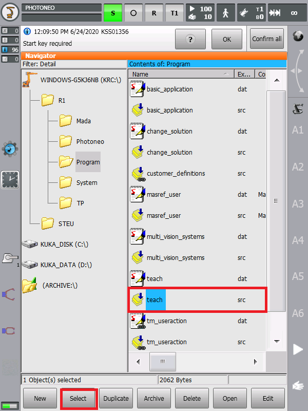

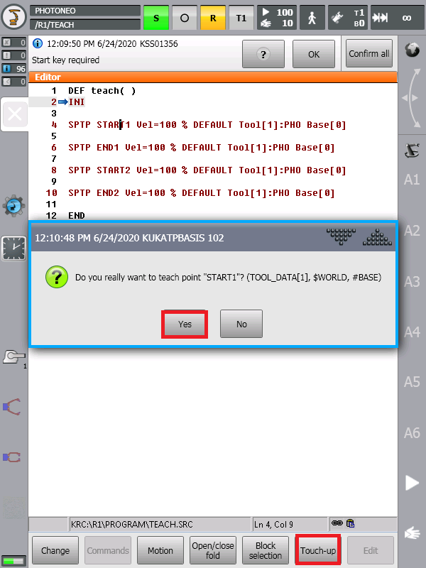
When more start/end positions are needed, they should be defined in this program and taught the same way as described above. These poses then need to be converted to AXIS representation before being used as parameters of the Initialization request (see the Initialization request for more details).
Note: When defining a new position, the keyword GLOBAL needs to be added to the position declaration inside the teach.dat file in order to be able to use this position outside the teach.src.
Teaching the home and placing poses
Teach the home pose and the placing positions directly from the main program.
Warning: Ensure that the home pose is reachable from last placing pose without collision. The robot might move to the home pose directly when an error occurs!
4.4 Runtime
Deploy your BPS solution. The Action Request Client status on the Deployment page of the BPS should be ** DISCONNECTED ** (from the Action Request Server).
Choose if you want to run the application in T1, T2 or AUT mode and adapt the speed override if required.
Select the basic_application.src from the R1/Program/ folder:

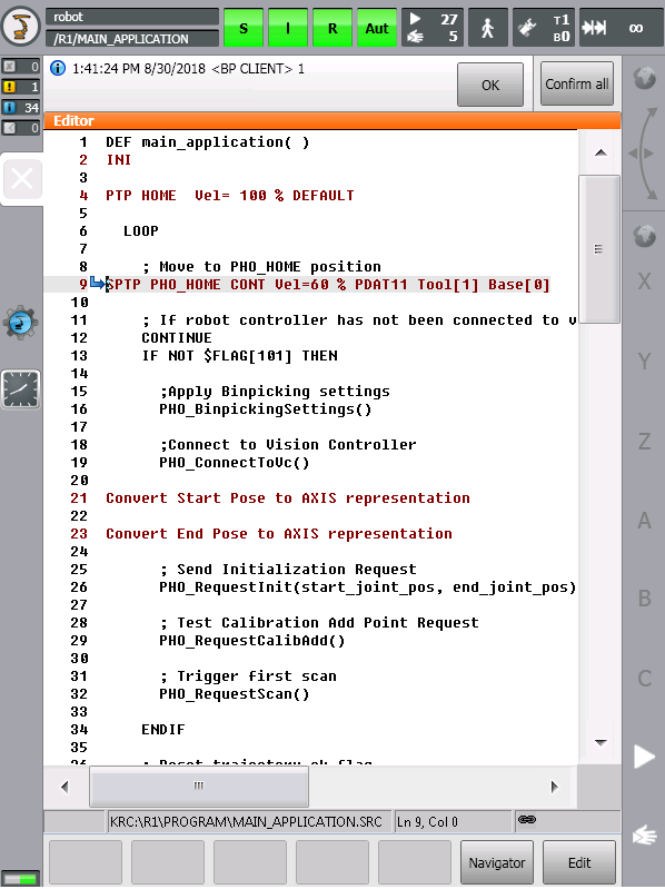
The robot should now start sending requests to the Vision Controller and execute bin picking movements.
NOTE: Ensure that you are ready to halt motion execution immediately in case of any problem. It is strongly recommended to reduce the speed to 10% of maximum or less during initial bin picking tests.
Since KUKA UI does not provide a standard “Terminal” utility, users are recommended to use Display tool to monitor values of specific bin picking related variables.
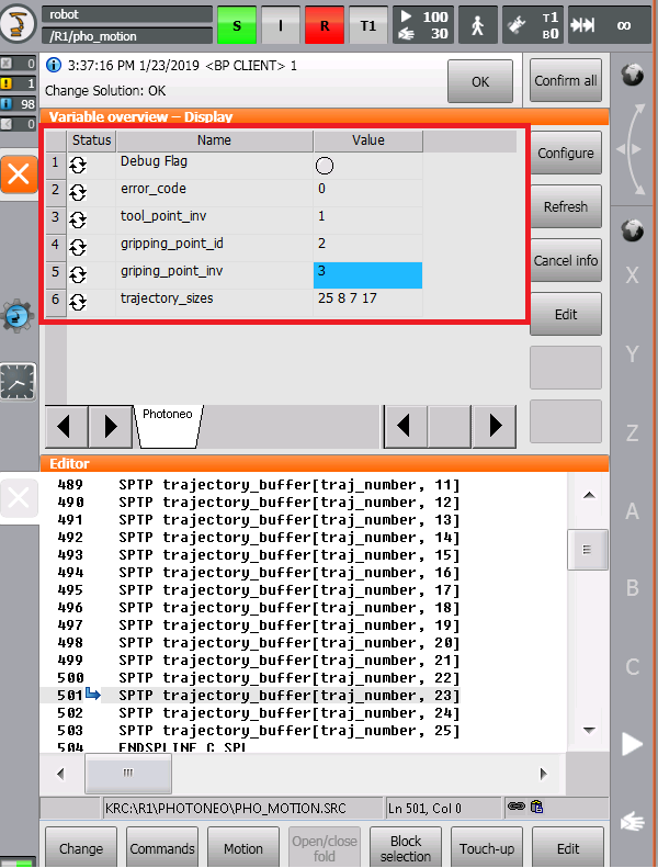
5 Migration guide
This chapter will walk you through the process of updating your robot module to a newer version. It also documents program flow, API, and other changes to help you make all necessary modifications in your current program without encountering any problems.
5.1 BPS 1.1.x -> BPS 1.2.x
NOTE: Migration between these versions does require robot module update as described in chapter 5.6 as well as update of the main program according to changes in API.
Changes in API calls as well as new calls are described in the table below:
API call |
Bin Picking Studio 1.1.x |
Bin Picking Studio 1.2.x |
Version compatibility |
|---|---|---|---|
PHO_RequestInit() |
Global variable ‘vision_system_id’ does not exist. |
Global variable ‘vision_system_id’ specifies ID of the selected Vision System for the request call. |
Changed. |
PHO_RequestScan() |
Global variable ‘vision_system_id’ does not exist. |
Global variable ‘vision_system_id’ specifies ID of the selected Vision System for the request call. |
Changed. |
PHO_RequestTrajectory() |
Global variable ‘vision_system_id’ does not exist. |
Global variable ‘vision_system_id’ specifies ID of the selected Vision System for the request call. |
Changed. |
PHO_CustomerRequest() |
Global variable ‘vision_system_id’ does not exist. |
Global variable ‘vision_system_id’ specifies ID of the selected Vision System for the request call. |
Changed. |
PHO_RequestPickFailed() |
Not available. |
Available.
Lower preference of the object because it failed to be picked. It won’t be chosen to be picked in the next cycle.
|
New. |
PHO_RequestCalibStart() |
Not available. |
Unsupported.
For Photoneo internal use only.
|
New. |
PHO_RequestBinLocator() |
Not available. |
Unsupported.
For Photoneo internal use only.
|
New. |
PHO_RequestChangeSol() |
Not available. |
Unsupported.
For Photoneo internal use only.
|
New. |
Changes in variables as well as new variables are described in the table below:
Variable |
Bin Picking Studio 1.1.x |
Bin Picking Studio 1.2.x |
Version compatibility |
|---|---|---|---|
vision_system_id |
Not available. |
Available.
ID of Vision System to be used in called requests. Change its value before calling a request for different Vision System.
|
New. |
tool_point_inv |
Not available. |
Available.
ID of Tool point invariance used for currently picked object.
|
New. |
gripping_point_id |
Not available. |
Available.
ID of Gripping point used for currently picked object.
|
New. |
gripping_point_inv |
Not available. |
ID of Gripping point invariance used for currently picked object. |
New. |
PHO_WRONG_BP_CONF |
Not available. |
Available.
Value = 255
Occurs when the bin picking configuration is incorrect. After receiving this error check the Bin Picking Studio console for more detailed information.
|
New. |
Other changes are described in the table below:
Subject |
Bin Picking Studio 1.1.x |
Bin Picking Studio 1.2.x |
Version compatibility |
|---|---|---|---|
Default port numbers |
Action Request Server on Vision Controller: 54602
State server on Robot Controller: 54601
User has an option to configure these values.
|
Action Request Server on Vision Controller: 54601
State server on Robot Controller: 54602
User is recommended to use these default values - it is not possible to configure port values in Bin Picking Studio by the user.
If you need to use specific port value please contact support@photoneo.com to help you with configuring port in Bin Picking Studio.
|
Changed. |
5.2 BPS 1.2.x -> BPS 1.3.x
NOTE: Migration between these versions does not require robot module update as described in chapter 5.6.
Changes in API calls as well as new calls are described in the table below:
API call |
Bin Picking Studio 1.2.x |
Bin Picking Studio 1.3.x |
Version compatibility |
|---|---|---|---|
PHO_RequestChangeSol() |
Unsupported.
For Photoneo internal use only.
|
Experimental.
Request to change deployed solution.
|
Unchanged. |
5.3 BPS 1.3.x -> BPS 1.4.x
NOTE: Migration between these versions does require robot module update as described in chapter 5.6. The main program, however, does not require any changes.
Changes in API calls as well as new calls are described in the table below:
API call |
Bin Picking Studio 1.3.x |
Bin Picking Studio 1.4.x |
Version compatibility |
|---|---|---|---|
PHO_RequestChangeSol() |
Experimental.
Request to change deployed solution.
|
Supported.
Request to change deployed solution.
|
Unchanged. |
5.4 BPS 1.4.x -> BPS 1.5.x
NOTE: Migration between these versions does require robot module update as described in chapter 5.6. The main program, however, does not require any changes.
Changes in variables as well as new variables are described in the table below:
Variable |
Bin Picking Studio 1.4.x |
Bin Picking Studio 1.5.x |
Version compatibility |
|---|---|---|---|
PHO_EMPTY_SCENE |
Not available. |
Available.
Value = 218
Error indicating that the scene (bin) is empty. Response to failed trajectory request.
Note: The error code is not defined in the robot module (pho_common.dat) as the other error codes. Please check the return value of procedure PHO_ReceiveTrajectory() using value 218 directly. |
New. |
5.5 BPS 1.5.x -> BPS 1.6.x
NOTE: Migration between these versions does require robot module update as described in chapter 5.6. The main program, however, does not require any changes.
Please read the general Migration guide here. The table below summarizes changes specific to the Robot module for KUKA (KRC).
Variable |
Bin Picking Studio 1.5.x |
Bin Picking Studio 1.6.x |
Version compatibility |
|---|---|---|---|
Error code [2]
UNKNOWN REQUEST
|
Unused. |
Removed. |
Changed. |
Error code [5]
TIMEOUT
|
Unused. |
Removed. |
Changed. |
Error code [6]
LONG TRAJECTORY
|
Unused. |
Removed.
The BPS won’t generate a too-long trajectory.
|
Changed. |
Error code [204]
PART LOST
|
Unused. |
Removed. |
Changed. |
5.6 Robot module update
Please follow these steps to update your current robot module to a newer version compatible with the Bin Picking Studio version you are using:
Back up current customer_definitions.src from Program folder. It contains your custom settings as well as gripper action procedures
Remove current customer_definitions.src from Program folder and whole current folder Photoneo from R1
Copy new customer_definitions.src to the Program folder and copy the whole new folder Photoneo to R1 (except for the new customer_definitions.src and teach.src and teach.dat)
Apply your modifications from old customer_definitions.src to new customer_definitions.src
Replace the old pho_bp_client.xml and pho_state_server.xml with new ones - edit the IP addresses
Carefully read the API changes in the new version of the robot module and modify your current API calls in your main program accordingly (if necessary)