Environment
Scene - offers the tools to build a 3D model of the robot’s environment
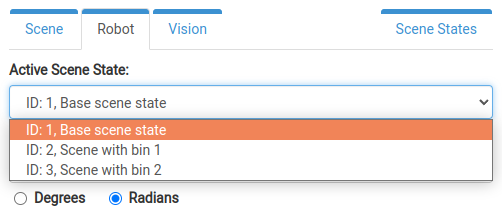
Robot - enables robot movement validation
Vision - allows connection to a calibrated vision system in order to capture a scan and compare the virtual environment with the real world
Scene States - serves for management of the states of the scene
- name:
environment_section
Contents
1 Scene
A precise 3D model of the real robotic cell is an essential prerequisite for collision-free bin picking. Although the trajectories are checked for collisions with the point cloud, the sensor never sees every object in the scene. Therefore, it is the responsibility of the user to define static collision objects matching reality.
The virtual environment created in Bin Picking Studio must match with the real world at least within the reach of the robot.
1.1 Object list
The Scene tab of the Environment page contains the Object list at the top (see Image 1 below). The list supports a hierarchical structure which means that any object can have child objects linked to it in order to ease the manipulation of a group of objects at once. Use the +/- buttons next to the parent object to expand/collapse the list of its child objects.
To change the hierarchy of already defined objects, the user can grab an object in the Object list and drag it to a desired position in the list. Note the + icon that appears when the object is dragged over another object to make it its child.
Every object in the Object list has an indicator and action buttons next to it. From left to right, they are:
Sync indicator - indicates whether the object is saved (synced) or unsaved (unsynced)
Visibility toggle - a toggle button to show/hide the object
Duplicate button - an option to duplicate the object
Remove button - an option to remove the object (please note that removing a parent object will also remove all of its child objects)

To add a new object to the scene, use the + Add object button above the Object list. A drop-down list appears with the following options:
Upload STL - Option to upload an STL file from a system directory
Box/Sphere/Cylinder - Primitive shapes that can be drawn directly in the visualizer
Group - An element that does not contain geometry and serves only as a container for child objects
When selecting a primitive shape or the Group object, the Edit form and the 3D object tools panel open directly so that it is possible to define its properties. When an STL file is chosen, a pop-up window appears: it is required to enter a name for the new object, choose the file to upload, and select the type of the object.
There are 3 object types:
Bin - Bin is meant for every CAD model that represents a bin. It is rendered in a blue color and, in future releases, bin objects may have more specialized options and parameters.
Environment - Other collision objects that correspond with real objects in the robot’s vicinity, rendered in grey.
Virtual collision object - Virtual collision objects may not necessarily exist in the robot’s real environment. These objects are rendered in red and, as the only object type, they appear semi-transparent. They are mainly applicable for limiting the robot’s working space during bin picking or for defining cell walls so as to allow see-through inspection of the (virtual) robot inside.
After selecting an object from the Object list, it is highlighted with a blue color in the list and becomes red in the visualizer. Besides that, the Edit form and the 3D object tools panel appear. It is also possible to select an object by directly clicking on it in the 3D visualizer too. To deselect an object, click on it in the Object list once again or choose the Close option next to the 3D object tools panel.
1.2 Edit form & 3D object tools
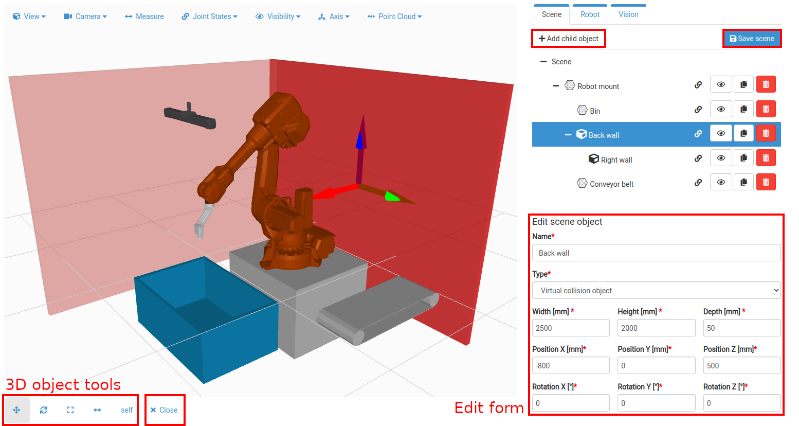
The Edit form allows for manual input of object properties. The available fields are:
Name - Define a name for the object.
Type - Select the type of the object as described in the previous section.
CAD file (mesh) - Download the object’s STL model or replace it (only for STL objects).
Scale - Scale the object (only for STL objects).
Dimensions - Resize the object (only for primitive shapes). There are fields for width, height, depth for a box, radius for a sphere, and radius and height for a cylinder.
Position - Change the position of the object’s origin relative to the parent object’s origin.
Rotation - Rotate the object around its own origin.
The 3D object tools panel enables the dynamic manipulation of objects. From left to right, the available options are:
Move - Change the position of the object along the desired axis by dragging a marker.
Rotate - Change the rotation of the object around the desired axis by dragging a marker.
Scale - Scale the object by dragging a marker.
Resize - Change the dimensions of the object along the desired axis by dragging a marker (only for primitive shape box and cylinder).
Self/Parent toggle - Change the origin of rotation when rotating using the marker. Select self for rotating around own origin or select parent for rotating around the parent’s origin.
Note: Since the Group object does not contain geometry, it only has a name, position, and rotation property.
The markers also allow the user to add increments to the position/rotation values for each axis. To do so, instead of dragging the marker in the desired direction, simply click on the marker arrow/circle for a specific axis to invoke a pop-up input field. Then, input the desired value of change and apply it by clicking the Check button.
Using the + Add child object button, it is possible to create a child object for the currently selected object. Use the x Close button to deselect the object (end editing).
After any change has been made, the button Save scene above the Object list becomes enabled. Use it to save the changes and synchronize the virtual environment with the robot. The Robot tab with robot controls may be used only after all changes to the virtual environment (scene) have been saved.
2 Robot
In order to access the Robot tab of the Environment page, a robot must be selected, the gripper set up, and the gripper’s tool point defined. Then it is possible to virtually jog the robot and define its working space.
2.1 Robot controls
There are three available motion modes:
Joint Virtual jogging of individual joints of the robot. There are two ways to jog the robot:
by moving the slider for the corresponding joint, or
- by manually entering the joint position in the input field
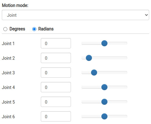
Image 3 - Robot controls panel with joint jogging motion mode
Linear (Tool coordinate system / Robot base coordinate system) Based on the selected option, it is possible to move the robot’s tool point in the coordinate system of either the tool or the robot base. There are three ways to move the robot:
by moving the marker in the robot’s tool point by dragging it to the desired position, or
by dragging the marker arrows to move it in each respective axis and by dragging the marker circles to rotate it, or
by manually entering the TCP position and orientation in the Tool point position panel
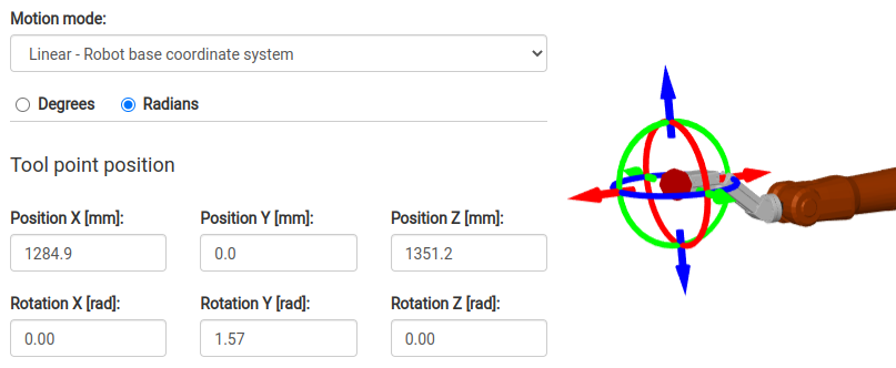 Image 4 - The Robot controls panel with Linear motion mode (Robot base coordinate system) and the marker for moving/rotating the robot’s tool point directly

2.2 Robot working space
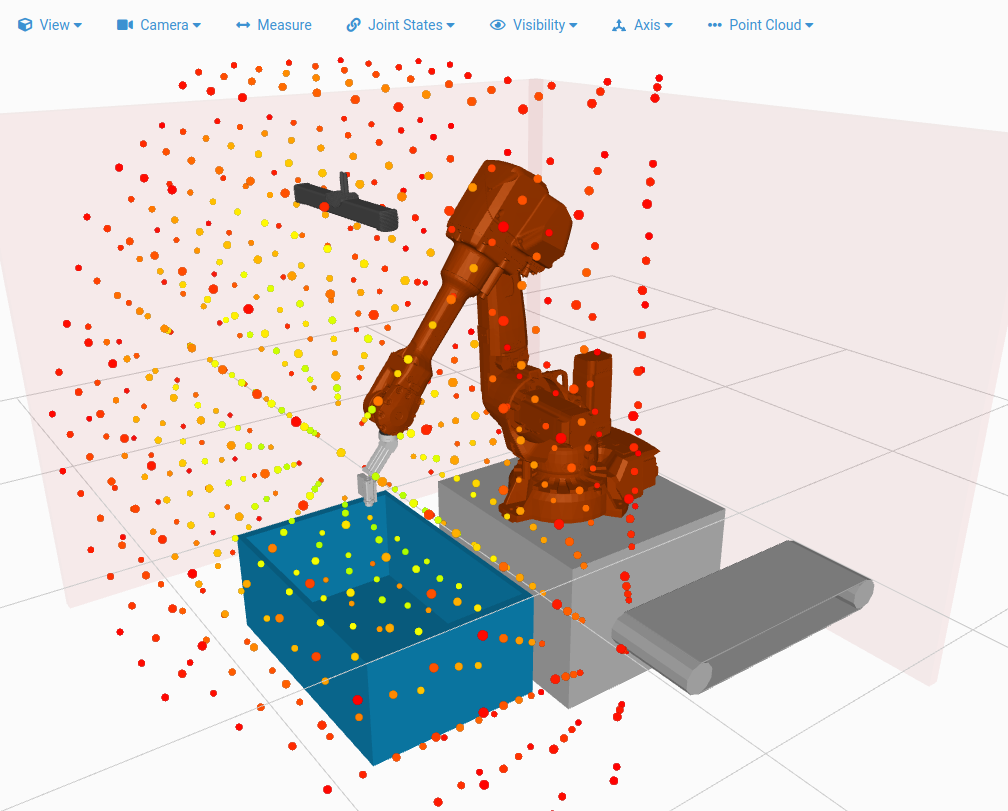
Robot working space enables visualization of the robot’s reachability and maneuverability. Robot’s ability to reach any place in the bin in various orientations is crucial for successful path planning. On the other hand, too much room for movement can also be a source of path planning failures. Section Joint limits provides further information about the importance of joint limits and their definition.
To visualize the robot’s working space (based on currently applied joint limits) press the Generate button. After a while, the working space will be displayed in form of dots of various colors (red-green gradient) which represent the robot’s ability to reach that particular point in space. The green color means the robot is able to reach this point from (almost) all directions while the red point is reachable only from a few. You should always aim for points of colors in the upper half of the red-green color gradient in the volume of the bin and above it (in the area where the path planning is done).
2.3 Joint limits
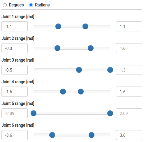
Joint limits allow the definition of the path planning working space of the robot.
During bin picking, the robot usually needs to move only in a fraction of its joint range. It is strongly recommended to set up the joint limits so that the path planning is taking place only in that subspace of the robot’s full workspace. Joint limits that are set up correctly have a positive effect on path planning computation time and success rate.
Leaving a joint limit field empty means that the robot’s default hardware limit will be used.
3 Vision
The Vision tab enables manipulation of the configured vision systems. Its main purpose is validation of the placement of collision objects.
Note: In case of MultiView vision system only the primary sensor is visualized in the virtual environment and can be used for scanning.
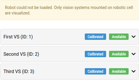
Based on availability of the sensor the vision system can be in one of the following states:
Available The sensor is ready to connect.
Not available The sensor is currently not ready to connect. Check its power supply, connection, and network configuration.
Based on robot-camera calibration of the vision system it can be in one of the following states:
Calibrated The vision system has been calibrated and can be used for calidation of collision environment.
Uncalibrated The vision system has not yet been calibrated. In order to use this vision system on the Environment page, a successful calibration must be performed first.
Simulated calibration The vision system has been manually placed in the collision environment. Solution containing such vision system cannnot be deployed in the production mode.
To view detailed information about a vision system, click on it in the vision system list. The window that appears contains:
Sensor ID
Calibration space and sensor position
Visibility controls Using the visibility menu, it is possible to turn on/off the visibility of the sensor model, scanning volume, and the origin of the sensor (more specifically its camera).
Sensor controls
Connect The button is enabled once the sensor is ready to connect.
Disconnect Once connected, it is possible to disconnect from the sensor using this button.
Trigger While connected to the sensor, trigger a new scan by pressing this button.
Edit button This option enables the user to manipulate the pose of the 3D sensor in the virtual enviroment. When satisfied with the result, by pressing button Save to vision system a new Simulated calibration matrix is created. Solution containing such vision system cannot be deployed in the production mode, however, it can be used the tune the solution settings.

Note: The Environment page shares sensor controls with the PhoXi Interface. Once connected on the Environment page, the same sensor is connected in the PhoXi Interface.
3.1 Validation
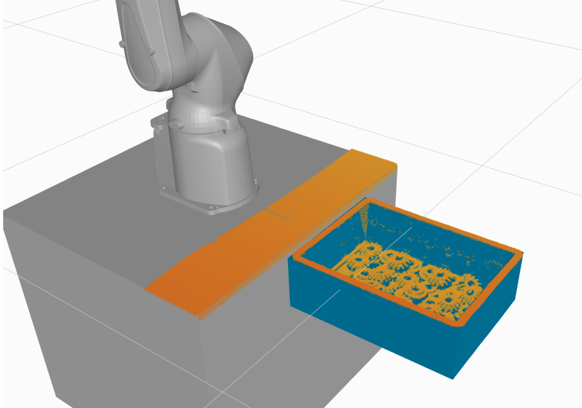
The Environment page’s ability to connect a sensor and trigger scans helps with the placement of collision objects (especially the bin), so that object’s model is matching reality precisely.
4 Scene States
4.1 Scene states management
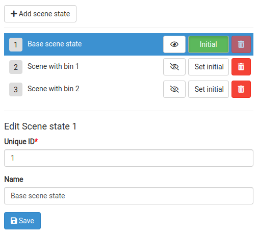
Visibility toggle - a toggle button to show/hide the scene state (when no scene state is selected to be displayed, all scene objects are visualized)
Set Initial button - sets the scene state as Initial. One of the scene states is always set as Initial. The Initial scene state is automatically activated when the solution is deployed
Remove button - an option to remove the scene state
To adjust the properties of a scene state, select it in the Scene state list - an edit form will appear that allows changing the state’s properties:
Unique ID - Through this ID the robot is able to request a scene state to be activated.
Name - An optional descriptive name of the scene state.
4.2 Scene
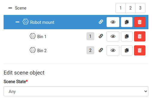
When using multiple scene states, every object has an additional property - affiliation to a Scene state. This property is set in the Edit form. Besides the defined scene states the scene state affiliation selector offers the option Any - the object is present in all scene states.
4.3 Robot