Contents
1 General settings
Initial gripping point placement method
Description:
This parameter defines the strategy for the initial placement of the gripping point. Gripping point placement depends on the type of objects localized in the application.
Values:
Dedicated methods:
These methods are tailored to compute the gripping point on a specific object type. They have a unique set of gripping point settings.
Center of Box
Center of Tote
General methods
These methods provide other approaches to computing the gripping point. They share the same set of Gripping point settings.
Centroid
Largest Inscribed Circle
Keypoint from NN
Center of Box
Strategy optimized for the localization of planar objects such as the side of a box.
Gripping point:
Position - the middle of the plane defined by the segmented top face of the planar object
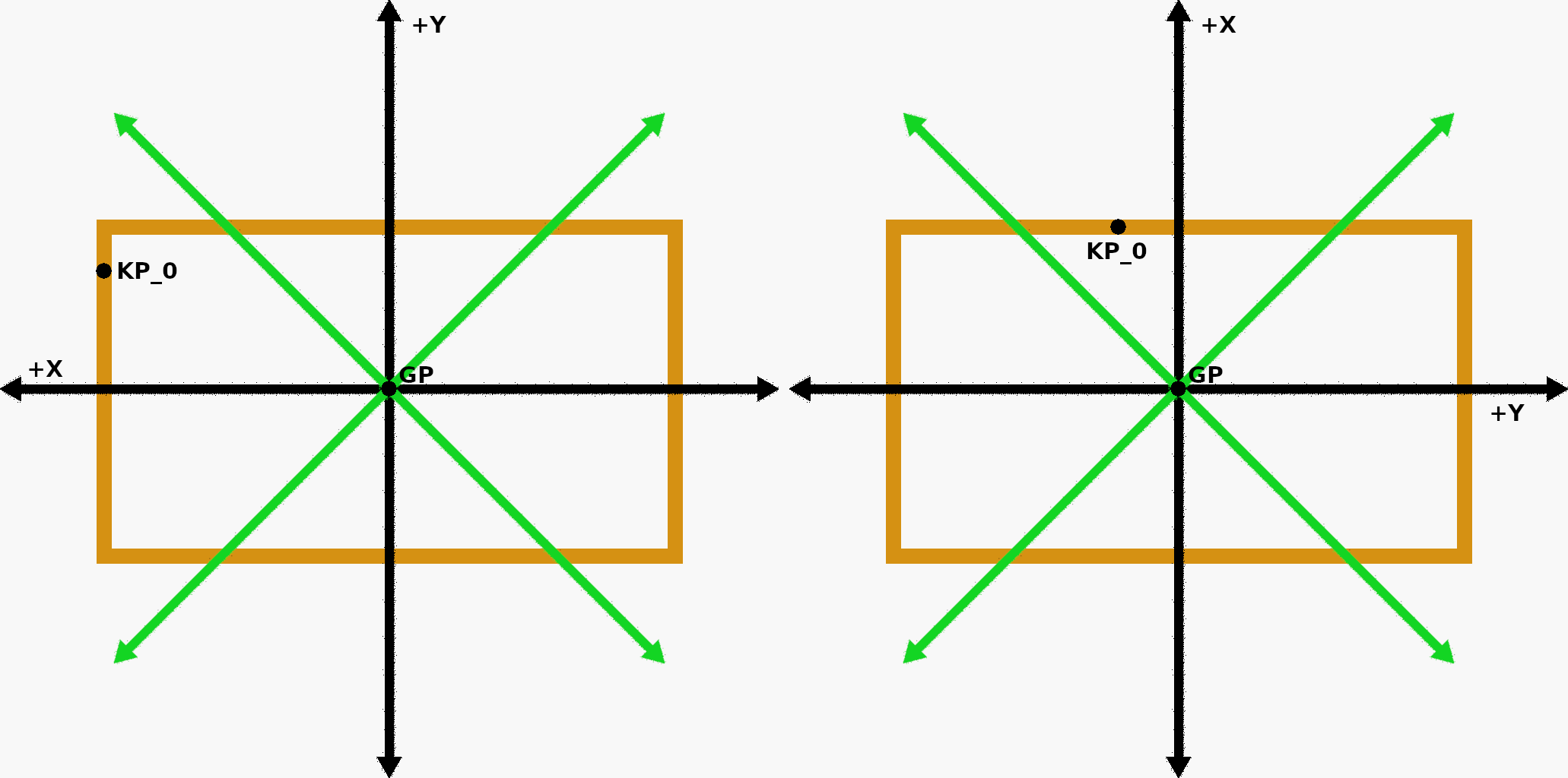
Orientation - the X-axis is parallel with the longer side of the box, its orientation is:
3D bounding box is enabled
The positive direction of the X-axis is the one for which the angle between it and the positive X-axis of the 3D bounding box coordinate system is less than 90 degrees.
3D bounding box is disabled
The positive direction of the X-axis is ambiguous.
Center of Tote
Strategy optimized for the localization of totes (KLTs), specifically their top face (rim). Calculated tote dimensions depend on the selected Tote edge detection point set (inner/outer).
Gripping point:
Centroid
The gripping point is placed in the centroid of the object (segment).
Orientation - the X-axis is parallel with the longer side of the bounding box of the object, its orientation is:
3D bounding box is enabled
The positive direction of the X-axis is the one for which the angle between it and the positive X-axis of the 3D bounding box coordinate system is less than 90 degrees.
3D bounding box is disabled
The positive direction of the X-axis is ambiguous.
Largest Inscribed Circle
The gripping point is placed at the center of the largest inscribed circle of the object (segment).
Orientation - the X-axis is parallel with the longer side of the bounding box of the object, its orientation is:
3D bounding box is enabled
The positive direction of the X-axis is the one for which the angle between it and the positive X-axis of the 3D bounding box coordinate system is less than 90 degrees.
3D bounding box is disabled
The positive direction of the X-axis is ambiguous.
Keypoint from NN
Notes:
- A Keypoint is a special feature on the object (segment).
- This option should not be used in combination with a Neural network that does not provide Keypoint position (depends on its training configuration). If this option is selected, automatically, the Centroid option is used for the initial gripping point placement, and the Object score of every found object is decreased 10 times (e.g., 0.9 -> 0.09). Therefore, the parameter Minimal object score must be lowered to have the objects localized.
The gripping point is placed at the Keypoint of the object (segment) as pre-trained.
Orientation - the X-axis is parallel with the longer side of the bounding box of the object, its orientation is:
3D bounding box is enabled
The positive direction of the X-axis is the one for which the angle between it and the positive X-axis of the 3D bounding box coordinate system is less than 90 degrees.
3D bounding box is disabled
The positive direction of the X-axis is ambiguous.
Neural network
Description:
Defines the neural network to be used for recognition.
Minimal object score
Description:
Defines the minimal required score of candidates recognized by the neural network. If a candidate has a lower score, it is rejected.
Use the Empty scene feature
Description:
The Empty scene feature allows the localization to stop prematurely with the response Empty scene when the number of points present in the scanning volume (or a bounding box) is below the Empty scene threshold .
Empty scene threshold
Description:
The threshold for the maximum number of points in the scanning volume (or a bounding box) to evaluate the scene as empty. In that case, localization stops prematurely with the response Empty scene.
Crop AI input according to the bounding box
Description:
When enabled, the projection of the 3D bounding box (if enabled) is used to crop the texture used for AI recognition.
Reject objects crossing bounding box
Description:
By default, objects (segments) outside the 3D bounding box and objects (segments) partially contained in the 3D bounding box (crossing it) are rejected.
When this setting is disabled, objects (segments) partially contained in the 3D bounding box (crossing it) can be accepted, provided their gripping points lie inside the 3D bounding box.
Note: Gripping point for an object is computed on the whole segment as reported by the neural network. Segments can be cut by the 2D bounding box applied to the texture before AI recognition. The application of the 2D bounding box is toggled by the setting Crop AI input according to the bounding box .
2 Gripping point settings
The set of available gripping point settings depends on the chosen Initial gripping point placement method.
The settings are further split into two categories:
Basic
These settings are commonly adjusted to achieve desired results.
Advanced (GP refinement)
These settings are used in special or complex situations to fine-tune the performance.
2.1 Dedicated methods
2.1.1 Center of Box
Box plane inliers distance tolerance (Basic)
Description:
The maximum allowed distance of a 3D point from the detected box plane to be considered a part of it. Lower values result in stricter plane detection, while higher values are more tolerant, but also forgiving towards outliers.
Minimum plane inliers threshold (Advanced)
Description:
The minimum required percentage of points from the segmented that must fit the detected plane for it to be considered valid. This helps ensure the detected plane is significant enough to represent the box surface.
Expected plane inliers threshold (Advanced)
Description:
Expected percentage of points from the segmented box that should fit the detected plane. This helps optimize the plane-search algorithm’s performance by providing an estimate of how many points should belong to the best plane.
Plane sampled points count (Advanced)
Description:
Number of points randomly sampled from the segmented box in each iteration of the plane-search algorithm to estimate a potential plane that fits the top of the box. A higher number can give more accurate results, but it increases computation time.
2.1.2 Center of Tote
Tote edge detection point set (Basic)
Description:
Determines which points are considered edge points of the tote:
Note: Reported dimensions of the tote are affected by this setting.
Tote edge fitting tolerance (Basic)
Description:
Defines the tolerance (in millimeters) for grouping points together when fitting lines to the tote edges. Points within this distance from each other are considered part of the same line segment. A smaller value results in more precise but potentially less stable line fitting, while a larger value is more forgiving but might lose some detail.
Line fit center weight radius (Basic)
Description:
Controls how much importance is given to points based on their distance from the center. Values between 0 and 1 create a weighting that emphasizes points closer to the center and gradually reduces the influence of points towards the edges. When set to 0 or 1, all points are weighted equally.
Segment border narrow (Advanced)
Description:
Sets a narrow border width for precise detection of the tote rim plane. Creates a thinner outline around the detected tote, providing more detailed edge detection. Best for clean, well-defined tote edges.
Tote edge fitting (Advanced)
Description:
Sets a wider border width for more reliable detection of the tote edge. It creates a thicker outline around the detected tote and helps filter out noise from the narrow border detection.
Edge filter radius (Advanced)
Description:
Specifies the radius (in pixels) used to determine if a point is on the edge of a tote. The algorithm checks points along a line in the direction toward or away from the centroid (based on edgePointsPosition setting). If all pixels within this radius are empty, the point is considered an edge point. Larger values create a more aggressive edge filter, requiring more empty space to identify edges.
Tote rim plane inliers distance tolerance (Advanced)
Description:
The maximum allowed distance of a 3D point from the detected tote rim plane to be considered a part of it. Lower values result in stricter plane detection, while higher values are more tolerant, but also forgiving towards outliers.
Minimum plane inliers threshold (Advanced)
Description:
The minimum required percentage of points from the segmented tote edge that must fit the detected plane for it to be considered valid. This helps ensure the detected plane is significant enough to represent the tote’s top surface.
Expected plane inliers threshold (Advanced)
Description:
Expected percentage of points from the segmented tote edge that should fit the detected plane. This helps optimize the plane-search algorithm’s performance by providing an estimate of how many points should belong to the top plane.
Plane sampled points count (Advanced)
Description:
Number of points randomly sampled from the segmented tote edge in each iteration of the plane-search algorithm to estimate a potential plane that fits the top of the tote. A higher number can give more accurate results, but it increases computation time.
2.2 General methods
Normal radius (Basic)
Description:
The gripping point normal (Z-direction) is averaged from the normals of 3D points lying within the defined radius.
Surface roughness compensation multiplier (Basic)
Description:
Defines how much, in terms of surface roughness (depth standard deviation), to move the gripping point towards the object (its surface) in the direction of the gripping point’s Z-axis. This can help when grasping soft objects with uneven surfaces.
Force the picking direction vector (Basic)
Description:
When enabled, the orientation of the gripping point’s Z-axis will be forced to:
Note: The sorter weight can be set to 0 as it is not relevant when the orientation of the gripping point is forced.
Suction cup radius (Advanced)
Description:
Defines the radius of the suction cup (the gripper). This setting is used only when the Coverage weight has a non-zero value.
Coverage weight (Advanced)
Description:
The importance of a good coverage of the suction cup (defined by the Suction cup radius ) when finding the optimal gripping point. With the increasing value of this parameter, the focus on placing the optimal gripping point on a surface with good coverage increases.
Distance weight (Advanced)
Description:
The importance of a low distance to the initial gripping point when finding the optimal one. With the increasing value of this parameter, the focus on placing the optimal gripping point close to the initial one increases.
Surface roughness weight (Advanced)
Description:
The importance of a low surface roughness when finding the optimal gripping point. With the increasing value of this parameter, the focus on selecting a smoother surface increases.
3 Dimensions reporting
The localization engine can report X and Y dimensions of the minimal bounding box of the localized object.
For rectangular-shaped objects, such as boxes or totes, the dimensions of the minimal bounding box approximately match the real dimensions of the object.
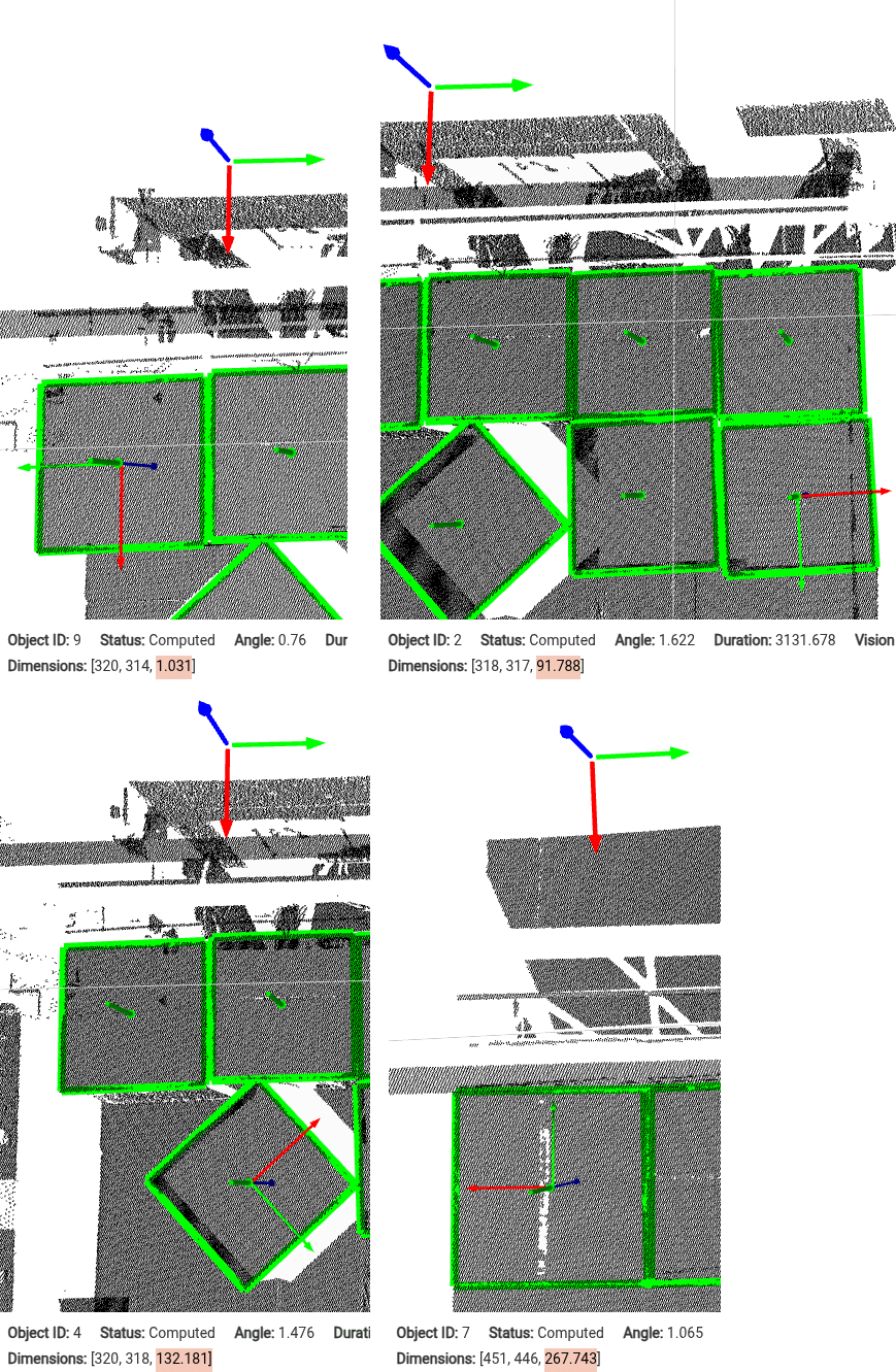
Apart from the X and Y dimensions, the angle of the positive X-axis of the object and the positive X-axis of the reference frame (calibration frame) is computed and reported together with the dimensions.
The range of the angle is 0-360 degrees, the angle increases in direction from the X-axis of the reference frame towards the Y-axis of the reference frame.
The figure below shows four different situations: Axes of reference frame (up), axes of the localized object (in the middle of the localized box), and the computed angle [degrees] in the Inspector widget (highlighted with orange).