Grasping methods
Grasping methods configurator allows definition of the bin picking routine, i.e. the sequence of trajectories and operations executed by the robot when the bin picking procedure (execution of bin picking) is called in the robotic program. It’s possible to configure various parameters of waypoints and trajectories between them, as well as actions that should be taken when the robot reaches a particular waypoint.
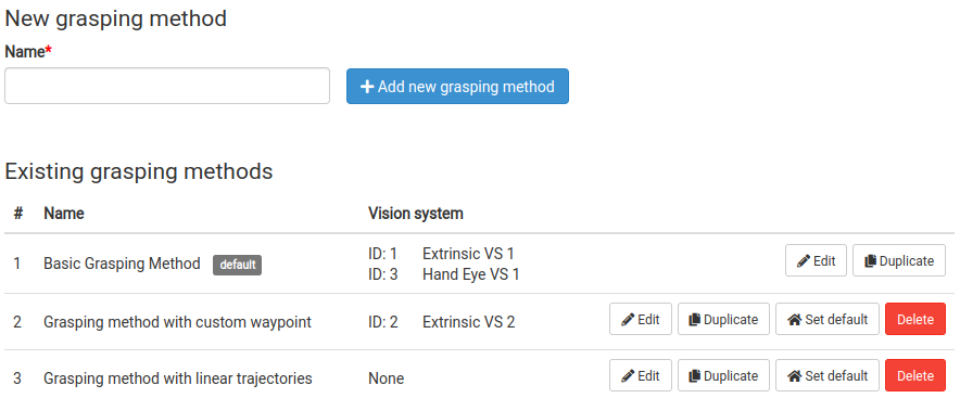
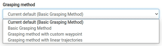
A single grasping method may not be applicable, or the most suitable, for all vision systems. Grasping method configurator allows definition of up to 5 different grasping methods. Each vision system can then be assigned one of these defined grasping methods.
Waypoint - a point in space that the robot’s tool-point (as defined in Bin Picking Studio) will move through during the bin picking routine. It is possible to define both the point’s position and a procedure to be executed when the robot reaches it.
Trajectory - a path joining two consecutive waypoints. It is possible to define the type of trajectory (joint/linear) and the desired precision. The precision parameter specifies whether it is necessary that the tool point come precisely to the given waypoint or whether the robot may approximate the motion and continue smoothly to the following trajectory.
Picking path stage - a single row of the grasping method configuration table that combines the settings of a waypoint and the trajectory leading to this waypoint.
Bin picking routine - a sequence of trajectories and operations executed by the robot when the bin picking procedure is called in the robotic program. The bin picking routine is normally executed in each cycle. It begins in the Start pose and ends in the End pose (as defined in the initialization request) with the picked object attached to the gripper.
Configuration overview
The configuration page of a specific grasping method contains the table with **Picking path stages. **The default configuration (see image below) consists of these mandatory stages:
Start - the starting position of the bin picking process defined in the initialization request
Approach - a relative offset from the grasp position
Grasp - the grasping position computed based on the Gripping point and Tool point definitions
Deapproach - a relative offset from grasp position
End - the ending position of the bin picking process defined in the initialization request
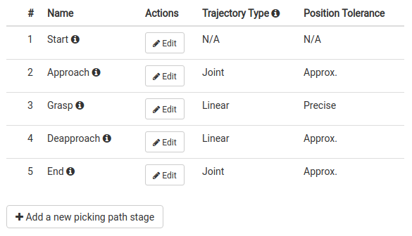
The table provides information about the following path stage parameters:
# (Order) - the position of the path stage in the bin picking routine as a whole
Name - the name of the path stage (waypoint)
Actions - the actions available for each individual path stage - Edit configuration and Delete (for custom ones)
Trajectory Type - the type of trajectory - Linear or Joint
Position Tolerance - the desired precision of arriving at the waypoint - Precise or Approximate
Picking path stage specification
Every path stage has several attributes that define the position of the waypoint in robot space and the trajectory that will lead to this waypoint.
Type - defines how the position is computed. It can be either a Fixed position in robot space or a Relative position from the gripping point of the currently approached picked object.
Name - a friendly name of the path stage (waypoint). Applies to custom path stages only.
Offset settings - applicable to waypoints positioned relatively to a given reference point.
Position settings - applicable to waypoints positioned absolutely within robot space.
Trajectory type - enforces linear motion if Plan linear trajectory is selected. Otherwise, joint-based trajectories are permitted.
Position tolerance - specifies how precisely the motion must pass through the given waypoint. The approximative setting may improve performance when precision is not paramount.
Procedure name - the procedure (if any) to be executed upon reaching the current waypoint.
Mandatory path stages
The default path configuration contains 5 mandatory path stages. The user is able to define up to six (6) additional custom path stages, for the maximum of 11 total path stages. Each mandatory picking path stage type is unique in its purpose. They may display a reduced set of options.
For example, Approach and Deapproach are always relative to the Grasp path stage. Start and End are defined in the initialization request and as such have no position settings. In addition, Start does not have a trajectory leading to it and so has no settings of that sort.
Note: Any custom path stages placed in the sequence after Approach and before Deapproach may be limited in terms of which settings may be changed. For example, linear trajectories are enforced for all path stages between Approach and Deapproach.
User-defined picking path stages
This part of the documentation contains a detailed explanation of each available path stage option.
Type
Relative - The target position is computed relative to the previous path stage.
Fixed - The target position is computed as a fixed point in robot space, i.e. relative to the base of the robot.
Name
The user may specify a friendly name of a custom path stage.
Origin of the relative offset (Relative positioning)
Found gripping point - in this case, the user defines an offset X, Y, Z relative to a found gripping point, whether this is during Approach or for Deapproach.
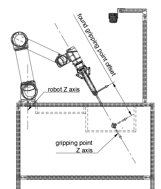
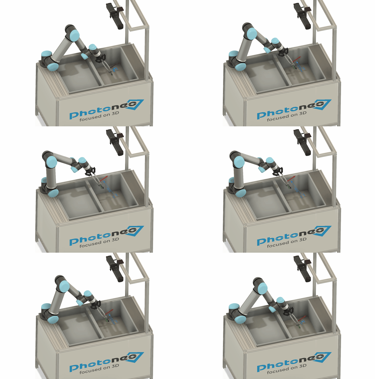
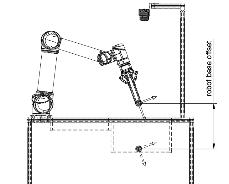
Robot - in this case, the user defines an offset in the X, Y, Z coordinates relative to the base of the robot.
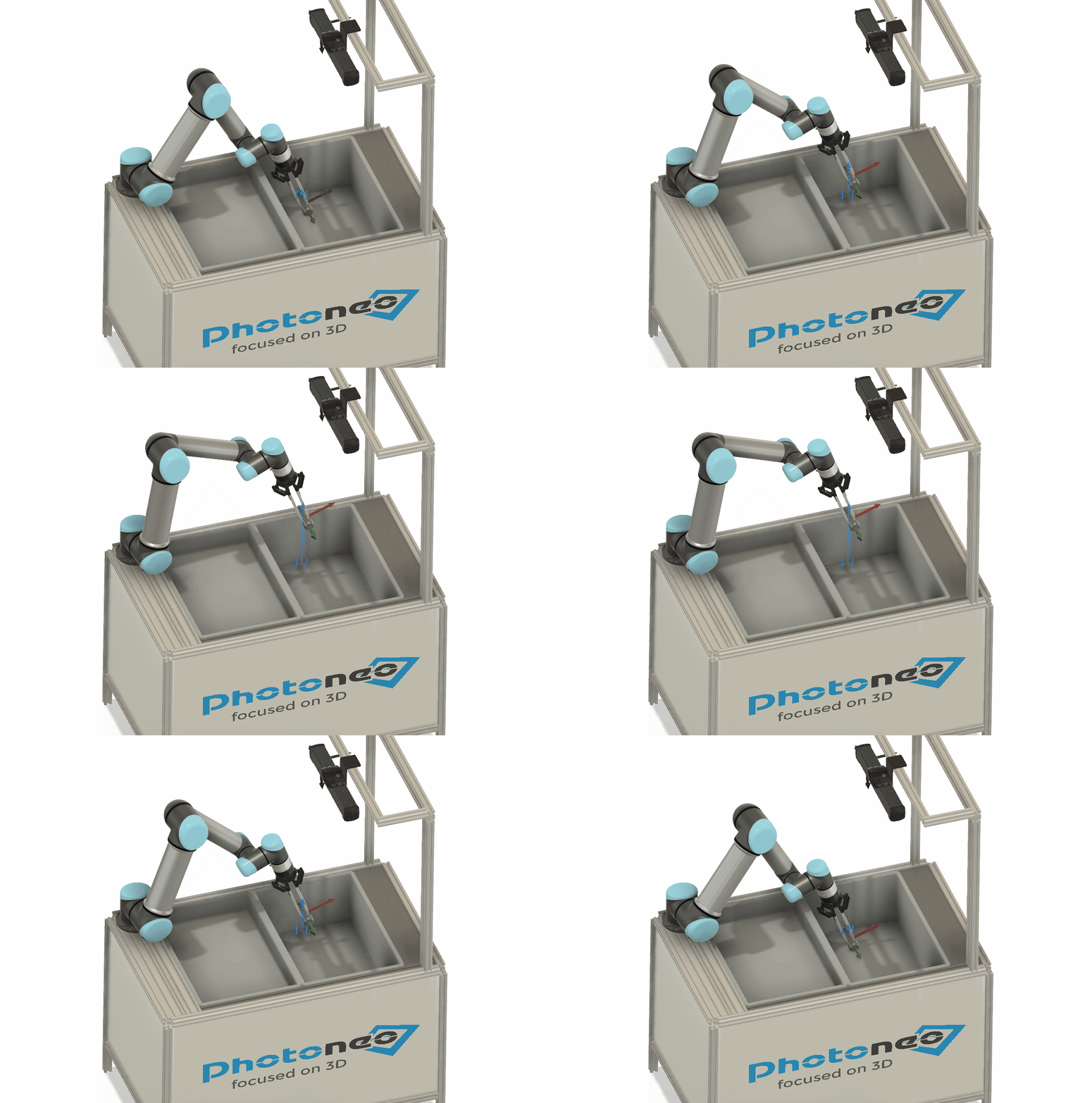
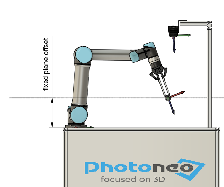
Fixed plane - The user is able to define one of these three fixed planes:
parallel to XY plane of the robot base (motion in the direction of Z-axis)
parallel to XZ plane of the robot base (motion in the direction of Y-axis)
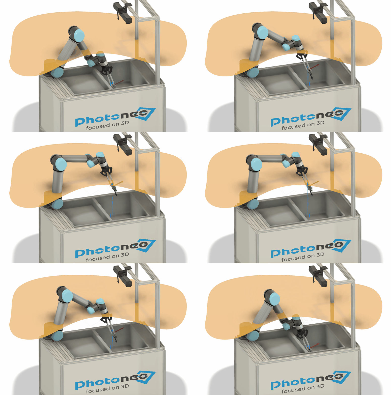
parallel to YZ plane of the robot base (motion in the direction of X-axis) The plane can be offset from the robot base by a a specific amount. The target waypoint is then defined during each cycle as having two of three components shared with the previous waypoint and the third one laying in the defined fixed plane on the intersection of a line perpendicular to the defined fixed plane and going through the previous waypoint (robot moves along the normal of the fixed plane going through the previous waypoint).
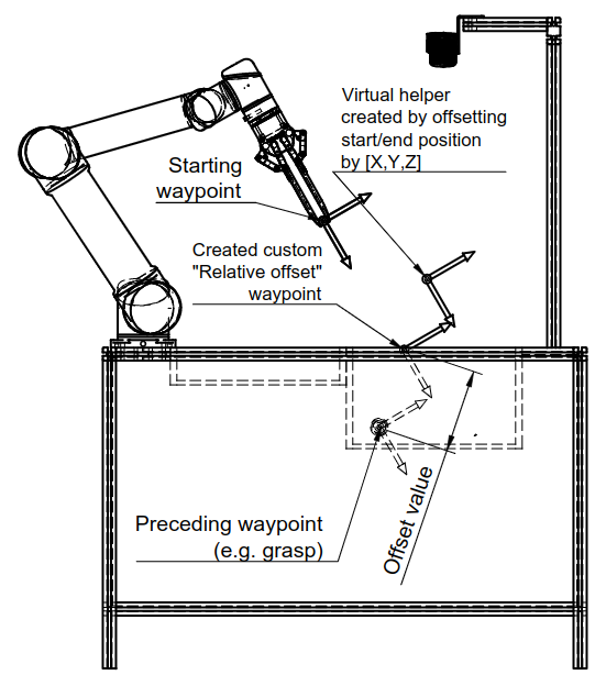
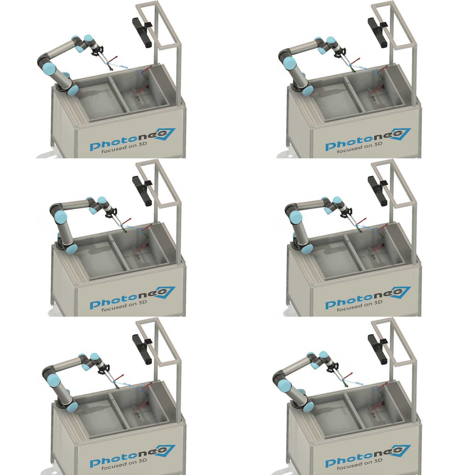
Start and End relative offsets - The user may specify an offset strictly in relation to the Start or End position as specified in the robot program. It is practical in situations where the user wants to navigate towards the middle of the bin, away from the bin walls. The robot will move towards the Start/End waypoint or the user is able to offset the Start/End waypoint using the Relative offset X/Y/Z fields in order to navigate towards this offset virtual waypoint. The length of the trajectory towards the Start/End waypoint or the virtual helper (distance between the previous waypoint and the new waypoint) is defined by the Relative offset value. If it is not, the new waypoint is the same as the Start/End waypoint (or the virtual helper). Note: The previous waypoint from which the trajectory length is specified is always considered in the direction from the Grasp waypoint (for a new waypoint between Start and Approach the previous one is Approach, for a new waypoint between Grasp and Deapproach the previous one is Grasp).
Absolute target position (Fixed positioning)
Plan linear trajectory
This checkbox controls whether the path planned to the current stage is strictly linear or based on joint movements. In some cases, linear trajectory planning is mandatory; moving to the Grasp stage must be linear, as well as to any other stages after Approach and before Deapproach (including Deapproach).
Position tolerance
Approximative - The robot reaches the specified point approximately and any robotic procedure may be called during the movement. Therefore, it is not recommended to use this option when a robotic procedure is selected in most cases. Refer to the manual of your specific robot for more information.
Precise - The robot reaches the specified point precisely and then the selected robotic procedure (if any) is called exactly at that position.
Procedure name
Select any user-defined procedure to be requested during this path stage. The selected procedure should be defined on the robotic controller and will be called by BPS during the picking process. The procedure will be called after the robot reaches the current waypoint, but may be called even during the maneuver if approximative position tolerance is set for the same waypoint.