Integration Guide Kawasaki LS
Note: It is strongly recommended to read the Robot communication overview prior to this integration guide.
Contents
1 Prerequisites
The Robot module is compatible with all E-series & F-series robot controllers.
2 Robot controller setup
2.1 Controller configuration
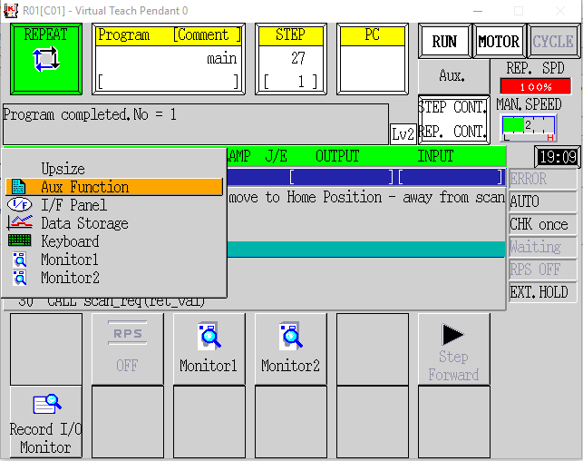
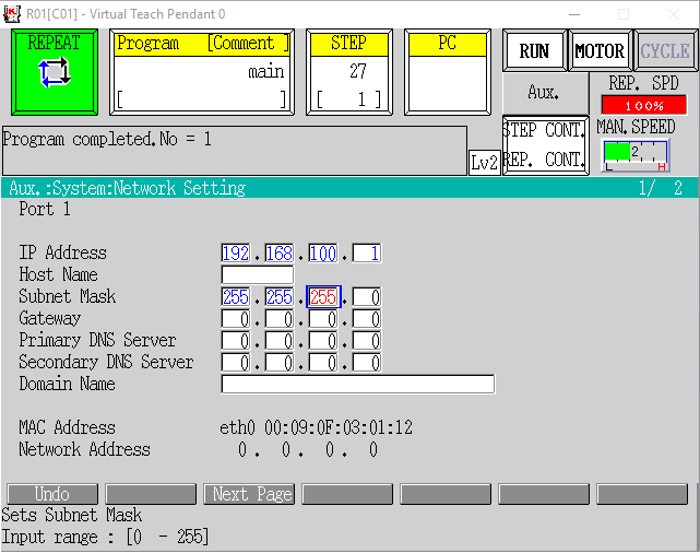
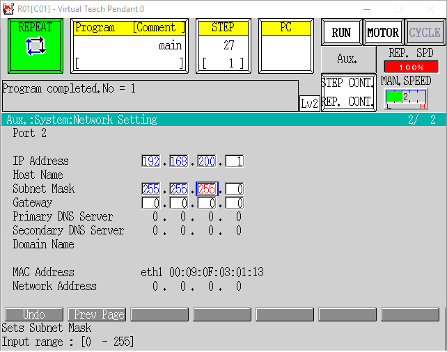
2.1.1 Network configuration

2.2 Robot module installation
2.2.1 Loading the Robot module files
The Robot module consists of a single core .pg file:
- photoneo_locator.pg
Besides that Photoneo provides an example locator program and a semi-automatic calibration example program located in folder example_programs:
- locator_example.pg
- calibration.pg
The core file (and optionally the example program if you wish to use it) need to be transferred to the robot controller to get the Robot module up and running.
You can copy the .pg files to the robot controller directly from the USB stick using the Pendant, however, the most convenient method of installation is to use the KRTerm tool (download_1, download_2).
Make sure that Port 2 is configured for communication with your PC and that both devices are connected to the same subnet (you must be able to ping the robot controller from the command line).
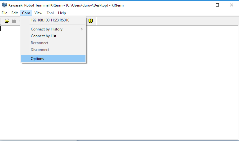
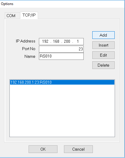
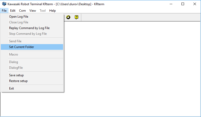
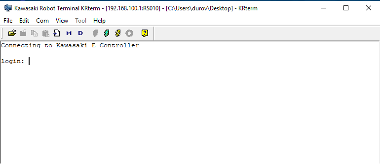
In order to load .pg files to the robot controller enter the LOAD command, e.g.:
LOAD photoneo_locator.pg
Make sure all files are loaded successfully.
At this point, the robot controller is configured to work with the Locator Studio.
3 Robot module
The Robot module is designed to be easily integrated into existing applications written in AS language.
3.1 Robotic API
Note: It is strongly recommended to read the Photoneo robotic API prior to this section.
3.1.1 Connection procedures
Warning: These procedures are contained in the photoneo_locator.pg API section and must not be edited!
Connection procedure |
Description / Usage |
|---|---|
Connect to Action Request Server connect_to_vc(.ret_val_conn) |
Description
Function to establish a new connection to the Action Request Server.
Input parameters:
Usage
The procedure should be called only once at the beginning of the program. Only after the connection has been established it is possible to send requests.
bp_port = 11003
vc_ip[1] = 192
vc_ip[2] = 168
vc_ip[3] = 0
vc_ip[4] = 80
CALL connect_to_vc (ret_val)
|
Close TCP socket close_socket() |
Description
Closes the open TCP socket.
Usage
Normally, it is not necessary to call this procedure as it is called automatically from the procedure Connect to Action Request Server if the socket is already open - reconnection is performed.
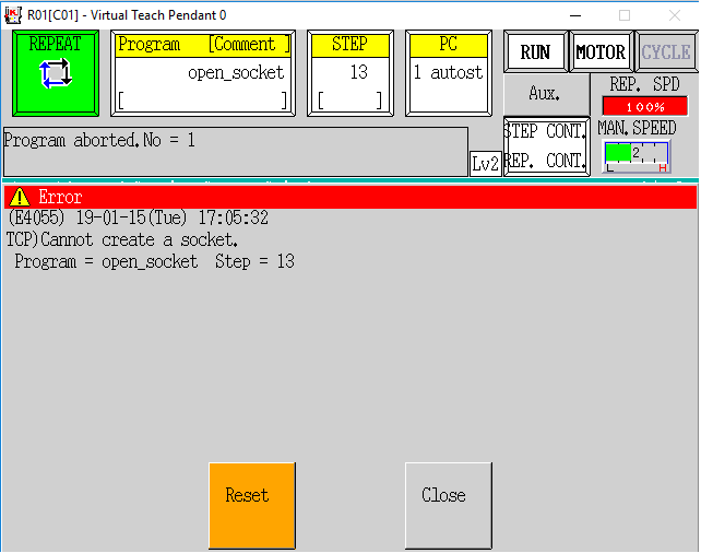
However, in some cases, it might happen the socket connection status variable does not report the correct status and the procedure Connect to Action Request Server fails (more specifically, its subprocedure
open_socket. Then this procedure (Close TCP socket) is used to close the TCP socket left open. |
3.1.2 Communication procedures
Note: Please read Action requests for detailed documentation of these procedures.
Warning: These procedures are contained in the photoneo_locator.pg API section and must not be edited!
vision_system_i - global variable. Locator requests require the vision system ID as an input parameter. It needs to be set to the correct value (ID of the vision system) before sending the request
.ret_val_X - procedure parameter. It stores the result of the procedure call.
Locator requests
Request |
Input variables |
Output variables |
|---|---|---|
Scan request
Variant A - Only for extrinsic VS
req_scan(.ret_val_scan) |
|
The result is accessible in two ways:
Note: The response is received by the procedure Wait for scan completion. |
Scan request
Variant B - Only for hand-eye VS
req_scan_tcp(.ret_val_scan,.&tcp_pose) |
|
The result is accessible in two ways:
Note: The response is received by the procedure Wait for scan completion. |
Get objects request
Variant A - Get a specific number of object poses
req_objects(.ret_val_pose,.requested_num) |
|
The error code is accessible in two ways:
|
Get objects request
Variant B - Get a single object pose
req_single_obj(.ret_val_pose,) |
|
The error code is accessible in two ways:
|
Get objects request
Variant C - Get all object poses
req_all_objects(.ret_val_pose,) |
|
The error code is accessible in two ways:
|
Calibration requests
Request |
Input variables |
Output variables |
|---|---|---|
Add calibration point request req_add_point(.ret_val_add) |
|
The error code is accessible in two ways:
|
Solution requests
Request |
Input variables |
Output variables |
|---|---|---|
Change solution request change_sol_req(.ret_val_sol,.solution_id) |
|
The error code is accessible in two ways:
|
Start solution request start_sol_req(.ret_val_sol,.solution_id) |
|
The error code is accessible in two ways:
|
Stop solution request stop_sol_req(.ret_val_sol) |
— |
The error code is accessible in two ways:
|
Get running solution request get_run_sol_req(.ret_val_sol) |
— |
The error code is accessible in two ways:
|
Response receiving procedures
Response receiving procedures |
Input variables |
Output variables |
|---|---|---|
Wait for scan completion wait_for_scan(.ret_val_wait) |
— |
The error code is accessible in two ways:
|
3.2 Example programs
The following section contains the Main program example and the calibration template which show the correct usage of the robotic API.
It is recommended to add suitable error handling for dealing with error situations.
3.2.1 Main program example
moves to a scanning pose where it requests a scan
moves to a starting pose above the tray in which it requests a specific number of object poses
if no error occurred, it picks the reported objects in loop:
the robot goes to an approach pose above the object
then it moves in a linear path towards the object and picks it (gripper command needs to be implemented here)
after picking, it moves in a linear path to a deapproach pose above the object
finally, the placing procedure is executed (needs to be implemented)
Name: locator_example.pg (located in folder example_programs)
.PROGRAM locator_example () ;
  ; *******************************************************************
  ;
  ; Program:      locator_example
  ; Comment:      Main program template with single vision system
  ; Author:       Photoneo s.r.o.
  ;
  ; Date:         20/10/2022
  ;
  ; *******************************************************************
  ;
  ;// Amend the Network settings - IP address of the Action request server (Robot interface)
  vc_ip[1] = 192
  vc_ip[2] = 168
  vc_ip[3] = 0
  vc_ip[4] = 80
  ;// Amend the Network settings - Action request server port (unrecommended)
  bp_port = 11003
  ;// Connect to the Vision Controller
  CALL connect_to_vc (ret_val)
  ;// Check return value, abort in case of failure
  IF (ret_val <> 0) THEN
    GOTO quit
  END
  ;// Set Vision System ID
  vision_system_i = 1
  SPEED 10 ALWAYS
  ;// MAIN LOOP
  WHILE (TRUE) DO
    ;// Move to Scanning pose in which the robot does not occlude the scanning area
    JMOVE #scanning_pose
    BREAK
    ;// Request scan acquisition
    CALL req_scan(ret_val)
    ;// Receive response from the scan request
    CALL wait_for_scan (ret_val)
    ;// Check return value, abort in case of failure
    IF (ret_val <> 0) THEN
      GOTO quit
    END
    ;// Move to Starting pose
    JMOVE #starting_pose
    ;// Request exact number of object poses
    .requested_num = 3
    CALL req_objects (ret_val, .requested_num)
    ;// Check return value, abort in case of failure
    IF (ret_val <> 0) THEN
      GOTO quit
    END
    ;// Pick all reported objects in loop
    FOR .i = 1 TO num_of_objects STEP 1
      ;// Move to Approach
      JAPPRO pho_obj_poses[.i], 100
      ;// Move to the reported object pose
      LMOVE pho_obj_poses[.i]
      BREAK
      ;// Activate gripper here
      ;// Move to Depart
      LDEPART 100
      ;// Execute placing here
    END
  END
  ;// End of the MAIN LOOP
quit:
  ;// Disconnect from the Vision Controller
  CALL close_socket
.END
3.2.2 Calibration example
This program is a template for semi-automatic calibration.
Before running the program:
teach the calibration start pose through which the robot will move to the individual calibration poses
teach the individual calibration poses
start the calibration in the Locator Studio
Now you can start the program. It will move to individual calibration poses and send the Add calibration point request when it reaches them. In between the calibration poses the robot will go through the calibration start pose. Once all the calibration points are successfully added, the program ends. If you are satisfied with the calibration result, save it in the Locator Studio.
Name: calibration.pg (located in folder example_programs)
.PROGRAM calibration () ;
  ; *******************************************************************
  ;
  ; Program:      calibration
  ; Comment:      Template for semi-automatic calibration
  ; Author:       Photoneo s.r.o.
  ;
  ; Date:         20/10/2022
  ;
  ; *******************************************************************
  ;
  ;// Amend the Network settings - IP address of the Action request server (Robot interface)
  vc_ip[1] = 192
  vc_ip[2] = 168
  vc_ip[3] = 0
  vc_ip[4] = 80
  ;// Amend the Network settings - Action request server port (unrecommended)
  bp_port = 11003
  ;// Connect to the Vision Controller
  CALL connect_to_vc (ret_val)
  ;// Check return value, abort in case of failure
  IF (ret_val <> 0) THEN
    GOTO quit
  END
  ;// Go to the start pose from which the robot will move to the calibration poses
  JMOVE #calib_start
  ;// 1. calibration point
  ;// Go to the first calibration pose
  JMOVE #calib_1
  BREAK
  PRINT "LOC_CLIENT: Adding the 1st calibration point"
  ;// When the pose is reached, call request to add the first calibration point
  HERE .tcp
  CALL req_add_point (ret_val, .&tcp)
  ;// Check return value, abort in case of failure
  IF (ret_val <> 0) THEN
    GOTO quit
  END
  ;// Return to the start pose
  JMOVE #calib_start
  ;// 2. calibration point
  JMOVE #calib_2
  BREAK
  PRINT "LOC_CLIENT: Adding the 2nd calibration point"
  HERE .tcp
  CALL req_add_point (ret_val, .&tcp)
  IF (ret_val <> 0) THEN
    GOTO quit
  END
  JMOVE #calib_start
  ;// 3. calibration point
  JMOVE #calib_3
  BREAK
  PRINT "LOC_CLIENT: Adding the 3rd calibration point"
  HERE .tcp
  CALL req_add_point (ret_val, .&tcp)
  IF (ret_val <> 0) THEN
    GOTO quit
  END
  JMOVE #calib_start
  ;// 4. calibration point
  JMOVE #calib_4
  BREAK
  PRINT "LOC_CLIENT: Adding the 4th calibration point"
  HERE .tcp
  CALL req_add_point (ret_val, .&tcp)
  IF (ret_val <> 0) THEN
    GOTO quit
  END
  JMOVE #calib_start
  ;// 5. calibration point
  JMOVE #calib_5
  BREAK
  PRINT "LOC_CLIENT: Adding the 5th calibration point"
  HERE .tcp
  CALL req_add_point (ret_val, .&tcp)
  IF (ret_val <> 0) THEN
    GOTO quit
  END
  JMOVE #calib_start
  ;// 6. calibration point
  JMOVE #calib_6
  BREAK
  PRINT "LOC_CLIENT: Adding the 6th calibration point"
  HERE .tcp
  CALL req_add_point (ret_val, .&tcp)
  IF (ret_val <> 0) THEN
    GOTO quit
  END
  JMOVE #calib_start
  ;// 7. calibration point
  JMOVE #calib_7
  BREAK
  PRINT "LOC_CLIENT: Adding the 7th calibration point"
  HERE .tcp
  CALL req_add_point (ret_val, .&tcp)
  IF (ret_val <> 0) THEN
    GOTO quit
  END
  JMOVE #calib_start
  ;// 8. calibration point
  JMOVE #calib_8
  BREAK
  PRINT "LOC_CLIENT: Adding the 8th calibration point"
  HERE .tcp
  CALL req_add_point (ret_val, .&tcp)
  IF (ret_val <> 0) THEN
    GOTO quit
  END
  JMOVE #calib_start
  ;// 9. calibration point
  JMOVE #calib_9
  BREAK
  PRINT "LOC_CLIENT: Adding the 9th calibration point"
  HERE .tcp
  CALL req_add_point (ret_val, .&tcp)
  IF (ret_val <> 0) THEN
    GOTO quit
  END
  JMOVE #calib_start
quit:
  IF (ret_val <> 0) THEN
    PRINT "BP_CLIENT: Error while adding the calibration point"
    PRINT "BP_CLIENT: Check the Studio for more details"
  END
  ;// Disconnect from the Vision Controller
  CALL close_socket
  HALT
.END
3.3 Error handling
If an error occurs during the execution of the operation requested by the sent request the error is stored in the return variable .ret_val_X and the global variable error_msg. It is recommended to implement adequate error handling for your particular application after each synchronous request and response receiving procedure.
Error codes together with their description and troubleshooting can be found here.
4 Running the Main program example
4.1 Prerequisites
Before the Main program example can be run, the following requirements must be met:
A fully configured solution with a single vision system must be prepared for deployment
The robot controller must be configured according to the chapter Robot controller setup of this integration guide
Locator Studio network settings must be configured
Gripper procedures should be implemented (optional - if not implemented, the robot will not actually pick the object)
The placing procedure should be implemented
4.2 Reteach the robot poses
The Main program example uses the following poses:
scanning_pose - scan acquisition is requested in this pose via scan request. For extrinsic vision systems, it is a pose in which the robot does not occlude the scanning area. For hand-eye vision systems, it is a pose in which the scanner on the robot has an optimal view of the scene.
starting_pose - a pose from which the robot moves to a pose above the reported object pose (an approach pose)
Besides these two poses, the placing procedure needs to be implemented.
4.3 Runtime
Deploy your solution. The Action Request Client status on the Deployment page should be ** DISCONNECTED ** (from the Action Request Server).
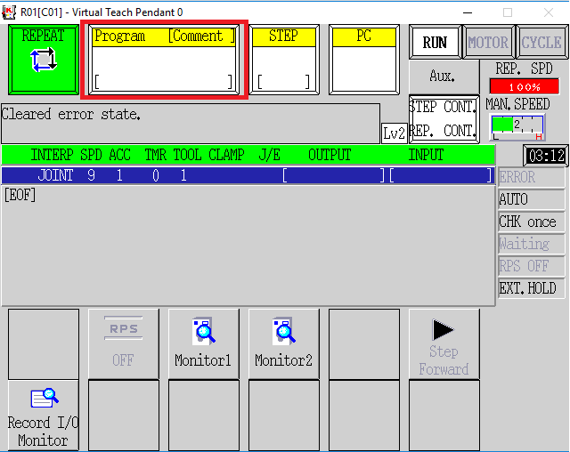
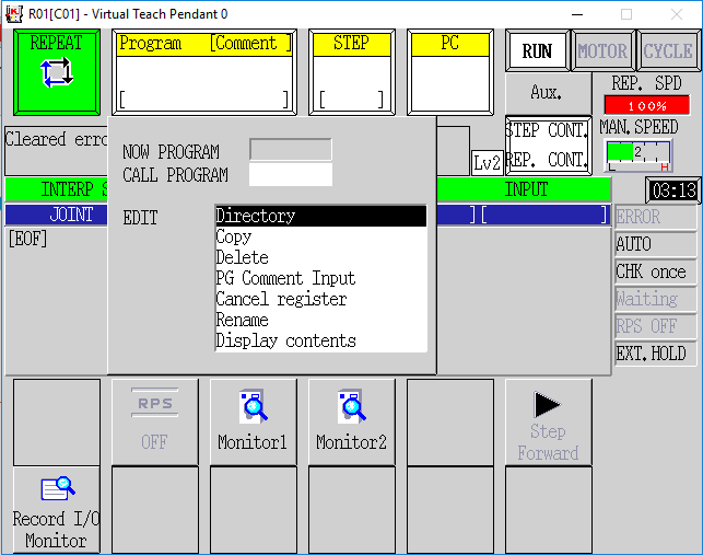
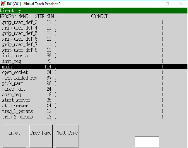
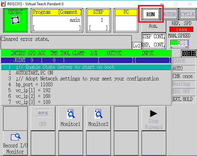
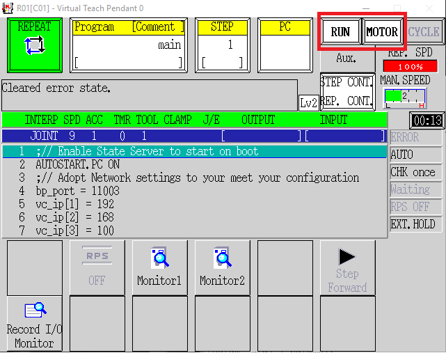
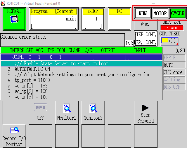
If you press Menu -> Keyboard on Teach Pendant, you should see text outputs as shown in the figure below signalizing that the Action Request Client is working properly.
As soon as the trajectory to the first localized object is calculated, the robot should start executing motion.
NOTE: Ensure that you are ready to halt motion execution immediately. It is strongly recommended to reduce the speed to 10% of the maximum during initial tests.
5 Troubleshooting