CAD feature alignment
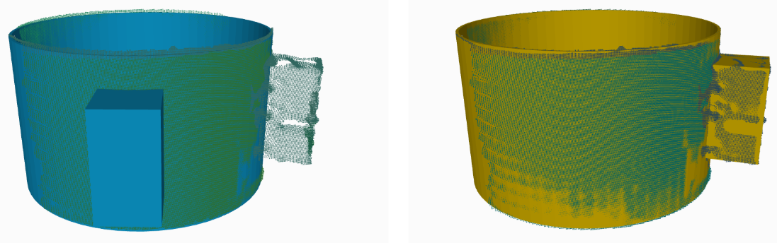
The key requirement for the use of Feature alignment is for the feature to be clearly visible on the scan. Use of this feature is fully optional - it might be possible to fine-tune the localization even without the use of this feature.
Contents
1 Model feature
A model feature is a part of the object that can be used to determine the exact pose of the object. For the localization to be able to use a feature for alignment it needs to be marked on the 3D model of the object by drawing a region of interest around it.
The tab Model Features of the Localization interface serves this purpose.
1.1 Model feature list
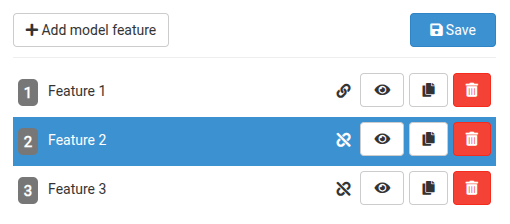
The Model feature list summarizes all defined features on the model of the object. It is possible to define up to 5 model features for a single object.
Controls
Status indicator - indicates whether there are pending unsaved changes to a model feature
Visibility toggle - enables showing/hiding a model feature
Copy button - enables copying an existing model feature
Delete button - enables removing an existing model feature
Image 2 - Model feature list
1.2 Model feature properties
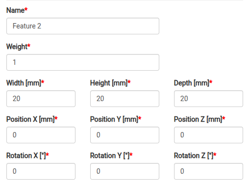
A model feature is defined by a set of properties:
Name - for simple identification of the model feature
Weight - defines the importance of the model feature relative to the other features.
Size (Width/Height/Depth) - defines the dimensions of the model feature
Position - defines the position of the model feature relative to the origin of the model of the object
Rotation - defines the rotation of the model feature relative to the origin of the model of the object
Move button
Rotate button
Resize button
Image 4 - Model feature drawing controls

1.3 Example
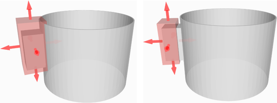
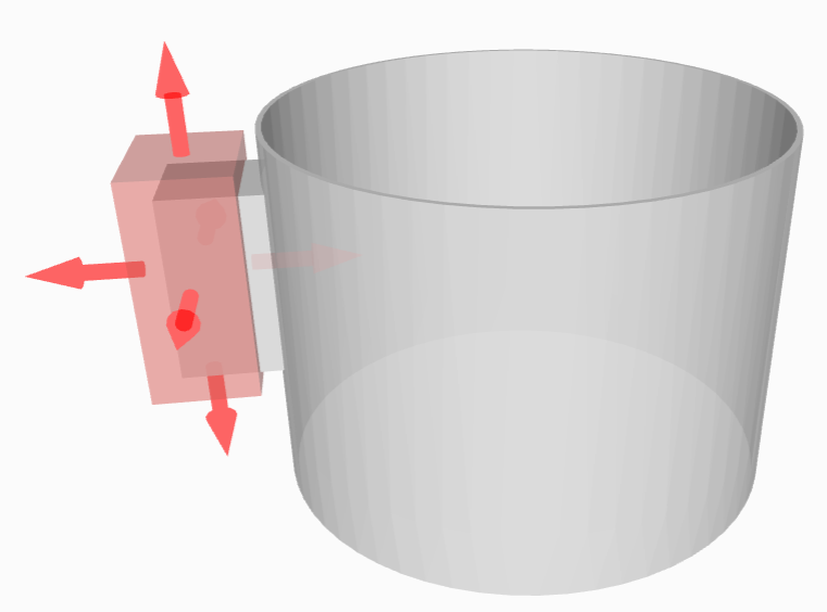
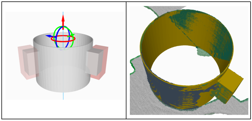
Consider a cylindrical object with a feature on its side. To prioritize the feature a region of interest is drawn around it (red box on the image below).
2 Feature alignment
2.1 Feature alignment list
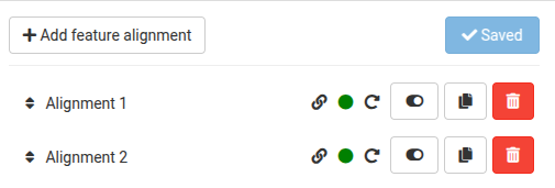
The Feature alignment list summarizes all defined feature alignments. It is possible to define up to 3 feature alignments for a single object.
Alignment execution order
Feature alignments are executed in the order as defined in the list. To change the order of the alignments drag an alignment up/down the list.
After the localization engine finds the object, it generates candidates for better alignment using the first alignment in the list. Only after the best of these candidates is found (the one with the highest overlap in the ROIs defining the model features), the second alignment is executed and so on.
Controls
Status indicator - indicates whether there are pending unsaved changes to a model feature
Activity indicator - indicates whether the alignment is enabled/disabled or enabled with no model features selected (which effectively disables it)
Alignment type indicator - indicates the alignment type (Rotation, Flip and Rotation or Translation)
Activity toggle - enables/disables the alignment
Copy button - enables copying an existing feature alignment
Delete button - enables removing an existing feature alignment
Image 6 - Feature alignment list
2.2 Feature alignment types
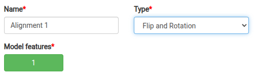
A feature alignment is defined by a set of properties. The common ones are:
Name - for simple identification of the feature alignment
Type - defines the type of symmetry of the object leveraged by the alignment
Model features - defines which model features are used by the alignment
The term axis of symmetry , when used in Feature alignment, refers to the symmetrical axis that an object typically possesses before the introduction of a feature making it asymmetrical.
2.2.1 Rotation
Properties unique to the Rotation alignment type:
Invariance axis - defines the axis of rotation symmetry of the object.
Basic mode - selection of axis parallel with X/Y/Z axis of the model origin
- Advanced mode - selection of an arbitrary axis.Tip: To define the axis, either direct input of vector values can be used or adjusting the marker in the 3D visualizer (recommended).
- Position - defines the position of the invariance axis relative to the origin of the model of the object (used when the origin is not lying on the axis of symmetry).Tip: To define the position, either direct input of offset values can be used or adjusting the marker in the 3D visualizer (recommended).
Steps - defines the number of candidates generated and tested for better alignment. Candidates are always generated uniformly in full range of the rotation symmetry (360°), Therefore the angular displacement difference between the neighbouring candidates is computed as 360°/Steps.

Example
Consider a cylindrical object with a feature on its side. The object can be localized incorrectly as rotated around its axis of rotation symmetry (blue) - the feature does not align with the point cloud.
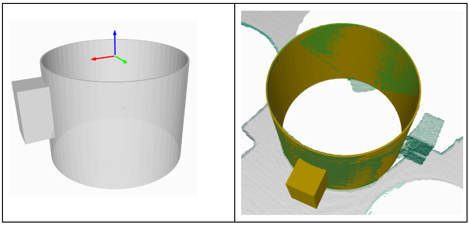
- Definition of the model featureImage 10 - Definition of the model feature
- Definition of alignmentThe axis is aligned with the axis of rotation symmetry of the model. When the model is being rotated, the model feature is rotating around the axis, the best candidate has the highest overlap in the model feature region:Image 11 - A preview of one of the candidates for the best feature alignment (left), correctly found object (right)
2.2.2 Flip and Rotation
Properties unique to the Flip and Rotation alignment type:
Invariance axis - defines the axes of rotation symmetry of the object.
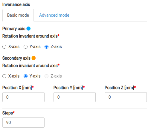
The Primary axis (blue) - defines the axis of line symmetry of the object
- The Secondary axis (orange) - defines the axis of rotation symmetry of the objectThese axes are always perpendicular to one another.
Basic mode - selection of axes parallel with X/Y/Z axis of the model origin
- Advanced mode - selection of arbitrary axes.Tip: To define the axis, either direct input of vector values can be used or, recommended, adjusting the marker in the 3D visualizer.
- Position - defines the position of the invariance axes relative to the origin of the model of the object (used when the origin is not lying on the axes of symmetry).Tip: To define the position, either direct input of offset values can be used or, recommended, adjusting the marker in the 3D visualizer.
Steps - defines the number of candidates generated and tested for better alignment around the Secondary axis (axis of rotation symmetry). Candidates are always generated uniformly in full range of the rotation symmetry (360°), Therefore the angular displacement difference between the neighbouring candidates is computed as 360°/Steps.
Comparison with doubled Rotation alignment
Flip and Rotation alignment is not a substitute for the double Rotation alignment where the first Rotation alignment would flip the model by 180° (around its axis of line symmetry) and the second one would rotate the model around the axis of its rotation symmetry. The same applies when the order of alignments is reversed (first rotation around the axis of symmetry and then flipping by 180° around the axis of line symmetry).
The difference in execution with Flip and Rotation alignment is that all combinations of rotating the model and flipping it are tested whereas with doubled Rotation they are not.
Execution order for doubled Rotation alignment:
Rotate the object using the first alignment and select the best candidate
Take the best candidate from the first alignment and rotate the object using the second alignment and select the best candidate
Execution order for Flip and Rotation alignment:
Rotate the object around its axis of rotation symmetry and for every rotation invariance also flip the model around its axis of line symmetry
Example
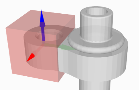
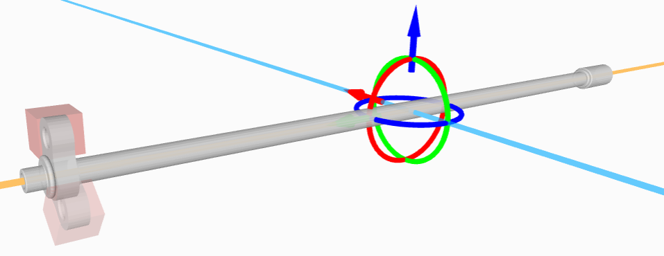
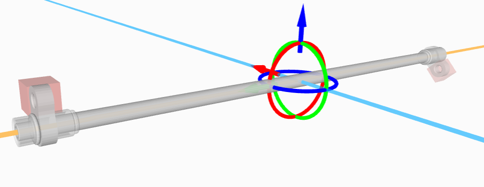
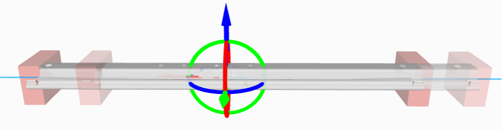
Consider a long cylindrical object with a feature on one of its ends. The object can be localized as flipped around its axis of line symmetry (green or red) - the feature being on the left or right side. It can be also localized incorrectly as rotated around its axis of rotation symmetry (blue) - even if the model was localized with the feature on the correct side, the feature does not align with the point cloud.
Flip and Rotation alignment can be used to find the correct position of the feature by searching for it on both ends - flipping the model around its axis of line symmetry while also rotating it around its axis of rotation symmetry.
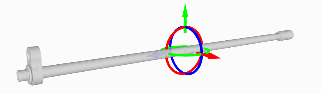
- Definition of the model featureImage 14 - Definition of the model feature
Definition of alignment
The primary axis is aligned with the axis of line symmetry of the model
- The secondary axis is aligned with the axis of rotation symmetry of the modelWhen the model is being rotated around the Secondary axis without the model being flipped around the Primary axis, the model feature is rotating on the left side of the model:Image 15 - A preview of one of the candidates for the best feature alignment, located on the left side of the objectWhen the model is being rotated around the Secondary axis with the model being flipped around the Primary axis, the model feature is rotating on the right side of the model:Image 16 - A preview of one of the candidates for the best feature alignment, located on the right side of the object
2.2.3 Translation
Properties unique to the Translation alignment type:
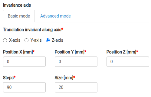
Invariance axis - defines the axis of translation symmetry of the object
Basic mode - selection of axis parallel with X/Y/Z axis of the model origin
- Advanced mode - selection of an arbitrary axis.Tip: To define the axis, either direct input of vector values can be used or, recommended, adjusting the marker in the 3D visualizer.
- Position - defines the position of the invariance axis relative to the origin of the model of the object (used when the origin is not lying on the axis of symmetry).Tip: To define the position, either direct input of offset values can be used or, recommended, adjusting the marker in the 3D visualizer.
Steps - defines the number of candidates generated and tested for better alignment
Size - defines the size of the translation difference between two neighboring candidates generated by the alignment
Example


- Definition of the model featureA model feature is defined on both ends of the model - when the model is localized correctly (without being shifted to one of the sides), the cumulative overlap value in both model feature regions is the highest. The cumulative overlap value drops when the model is found as shifted to one of the sides.Image 19 - Definition of the model feature
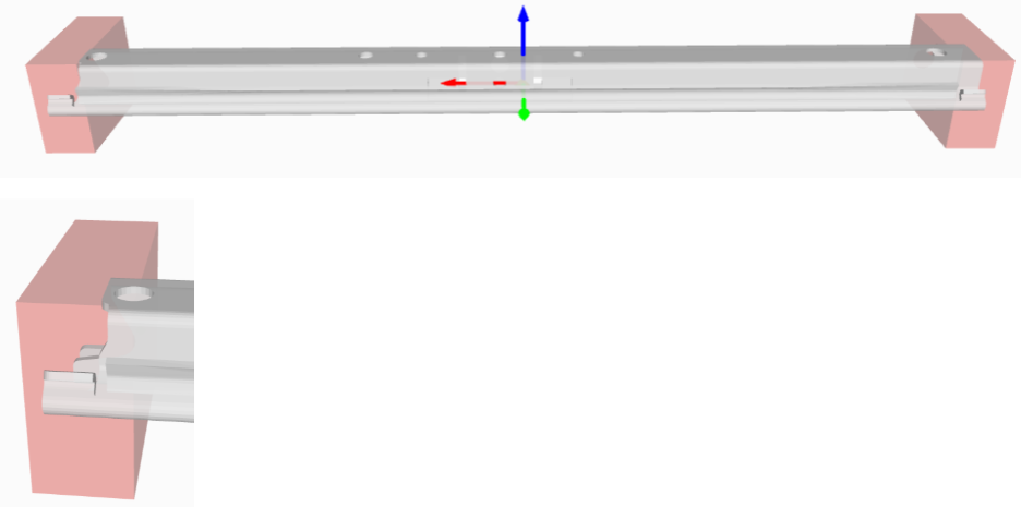
- Definition of alignmentThe axis is aligned with the axis of translation symmetry of the model When the model is being shifted to one of the sides, the model features are moving along the axis, the best candidate has the highest cumulative overlap in both model feature regions:Image 20 - A preview of one of the candidates for the best feature alignment (top), correctly found object (bottom)

3 Model feature alignment localization settings
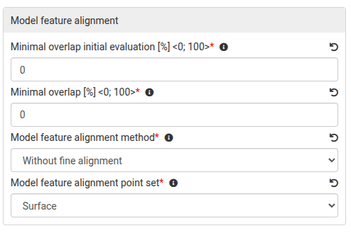
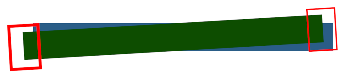
This setting can be used to quickly reject the original candidate for the localized object because it cannot be improved by the feature alignment process.
Blue - point cloud
Green - original candidate with model feature regions (red)
Accepted for feature alignment process if they are just shifted alongside the axis of translation symmetry because the cumulative overlap in all model feature regions will yield considerably high values - higher than the value of Minimal overlap initial evaluation threshold.
Rejected for feature alignment process if they rotated (and possibly also shifted alongside the axis of translation symmetry) because the cumulative overlap in all model feature regions will yield considerably low values - lower than the value of Minimal overlap initial evaluation threshold.
Left - object pose “guessed” by the localization engine with Minimal overlap = 0%
Right - object not found with Minimal overlap = 40%
Without fine alignment - The fine alignment algorithm is not applied.
With fine alignment - The fine alignment algorithm is applied.
Recurrent with fine alignment - The fine alignment algorithm is applied and feature alignment is repeated one more time.
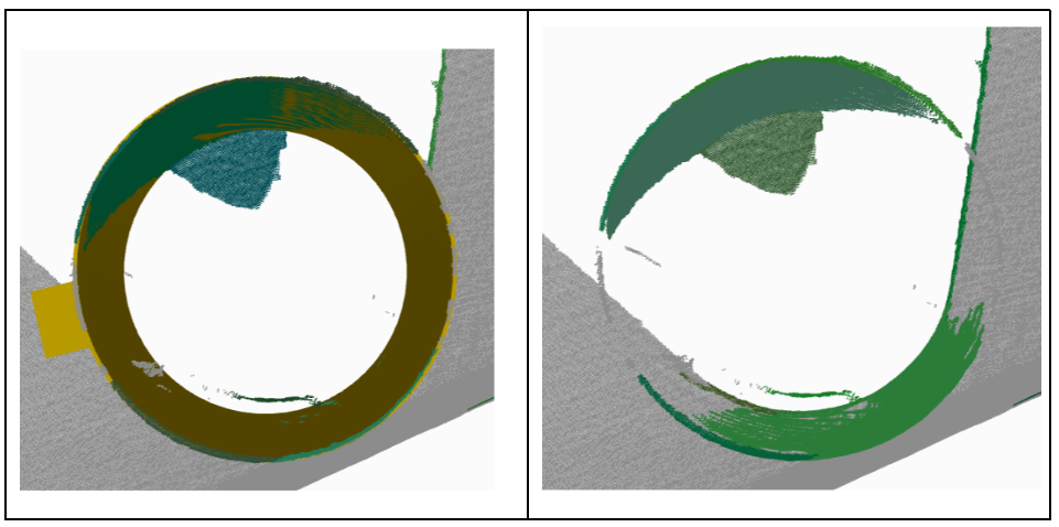
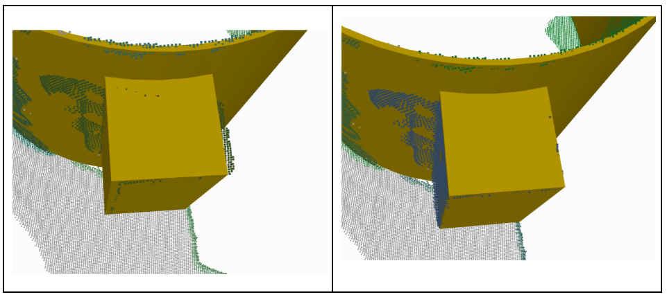
Left - object pose found by the localization engine with Model feature alignment method set to Without fine alignment
Right - object pose found by the localization engine with Model feature alignment method set to With fine alignment (improved)
Image 24 - Improved localization accuracy with fine alignment executed after Model feature alignment
Surface - useful for model features which do not have well-defined edges (surface is mostly rounded).
Edges - useful for model features which do have well-defined edges.