Gripping points
This page describes the Gripping point step of a solution, where you define where the gripper may grasp the picked object. It applies to CAD Picking solutions in Bin Picking Studio (BPS). In AI Picking solutions, the Studio finds the gripping points itself, see the gripping point settings of AI localization.
The page covers the ideas behind tool points, gripping points and invariances, the Studio forms, teaching a gripping point with the real robot, examples for common objects and grippers, and how the robot program can use the grasp for oriented placing.
Tool point and gripping point
Where and how the gripper grasps the object is one of the most important parts of a Bin Picking Studio (BPS) solution. It decides how often path planning succeeds and how fast the picking is. Two things define it:
the tool point – a point on the gripper, set in the Gripper step,
the gripping points – points on the picked object, set in the Gripping point step.
Together with the grasping method, they make up the bin picking routine. During the grasp, the tool point and one gripping point meet: their coordinate systems are laid on top of each other.
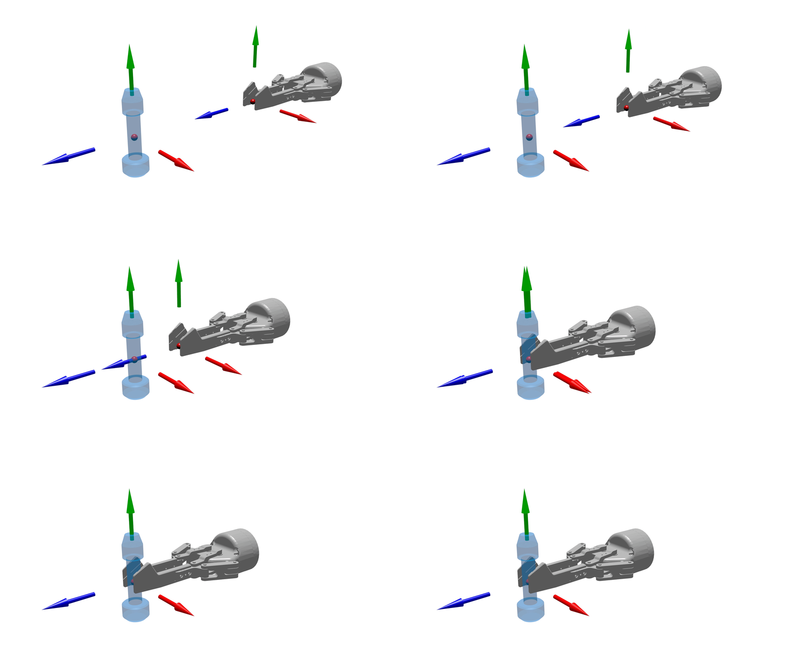
During a grasp, the coordinate system of the tool point is aligned with the coordinate system of the gripping point
Badly defined tool points and gripping points create unnecessary grasp combinations and slow down the picking.
Tool point
The trajectories that BPS sends to the robot are in joint space: each point gives the angle of every joint. BPS still needs to know where the tool is, so it uses its own tool point instead of the TCP set on the robot controller.
The tool point is defined relative to the origin of the gripper CAD model. That origin must be where the gripper is mounted on the robot flange.
The Z-axis of the tool point points out of the gripper.
A gripper has one tool point.
Gripping point
Good gripping points depend on the shape of the object, its material and the gripper.
A gripping point is defined relative to the origin of the picked object CAD model.
An object can have any number of gripping points.
Gripping points are needed only in CAD Picking solutions. In AI Picking solutions, BPS finds them itself.
A change of the tool point affects how every gripping point is reached. A change of one gripping point does not affect the others.
Invariance
Many objects and grippers look the same after a turn around an axis. Such a turn is called an invariance. Setting it up gives the robot more ways to grasp the object, without defining more gripping points.
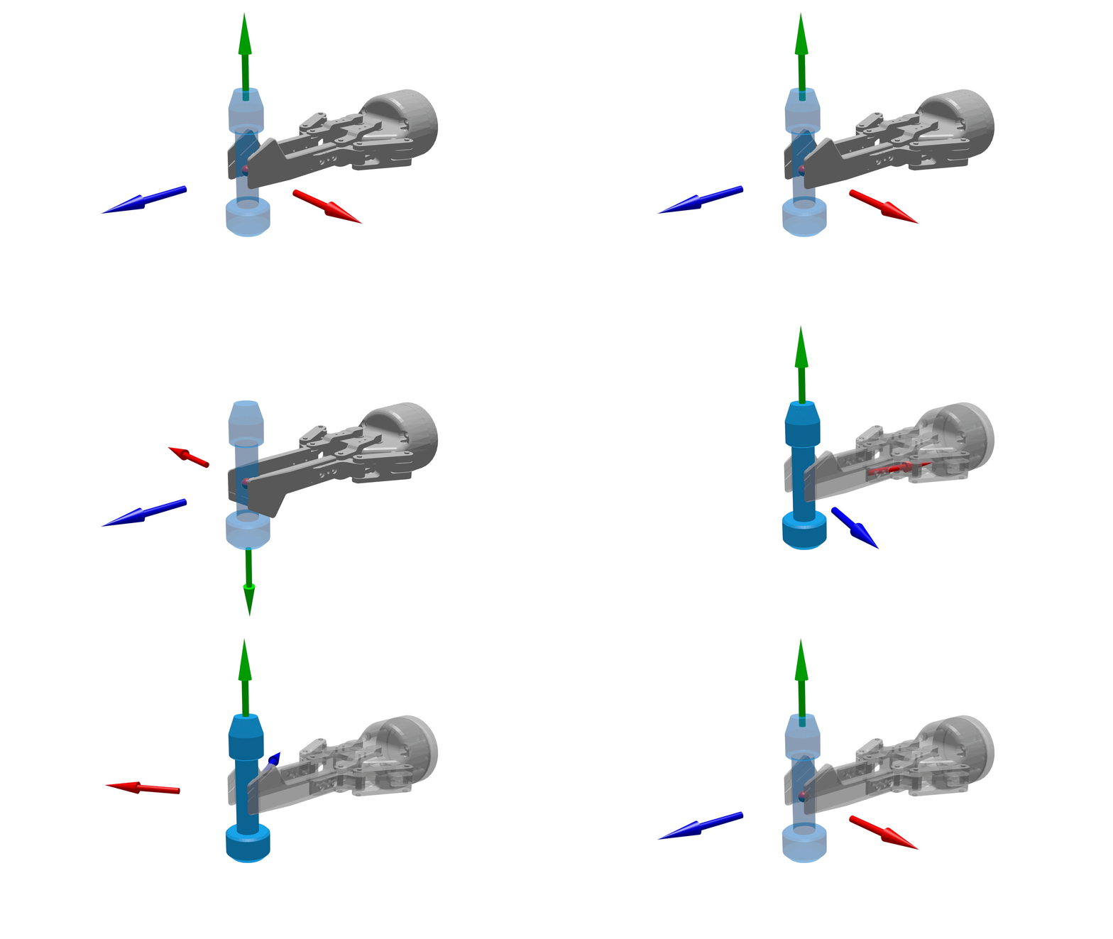
The invariance axis of a gripping point on the object (green) and of the tool point of a two-finger gripper (blue)
Gripping point invariance – the object above is symmetrical around its Y-axis (green). From the top or the bottom it matters how it is turned, but from the side, a two-finger gripper grasps it the same way at any angle. The object is invariant to any turn around its Y-axis.
Tool point invariance – the two-finger gripper above grasps the object the same way when it is turned by 180° around its Z-axis (blue). Unlike the object, it is not invariant to any turn, only to two positions: 0° and 180°.
Correct tool point invariances give the best picking performance.
Some invariance steps may not be graspable, for example a metal object with one plastic side picked by a magnetic gripper. Disable those steps. For the invariance fields and the step buttons, see Rotation invariance.
Multiplying invariances
The invariances of the tool point and of the gripping point multiply. In the example above, a gripping point with 8 invariance steps and a two-finger gripper with 2 give 8 × 2 = 16 ways to grasp the object. The two axes are perpendicular, so no grasp repeats. This is a good setup.
It is different when both axes are the same. A magnetic gripper or a suction cup is invariant to any turn around its Z-axis, and a gear lying under it is invariant around the same axis. Gripping point invariances around that axis add nothing new: 8 steps on the gripper and 8 on the gripping point give 64 combinations, most of them the same grasp. These redundant combinations slow down the picking.

|
|
Invariances around the same axis on both can be valid in some cases. Just avoid combinations that repeat the same grasp.
Using invariances instead of more gripping points
The magnetic gripper can pick the gear above by its top or its bottom face. There are two ways to set this up:
Two gripping points, one on each face, without invariances. The gripper is already invariant around its Z-axis, so this is enough.
One gripping point with two invariance steps. For the magnetic gripper, the gear looks the same when flipped by 180° around any horizontal axis through its centre. One gripping point with two steps covers both faces.
Both work. One gripping point is easier to maintain: a change of the grasp settings, or a new tool point, is done in one place. Separate gripping points can have different priorities.
Gripping point list
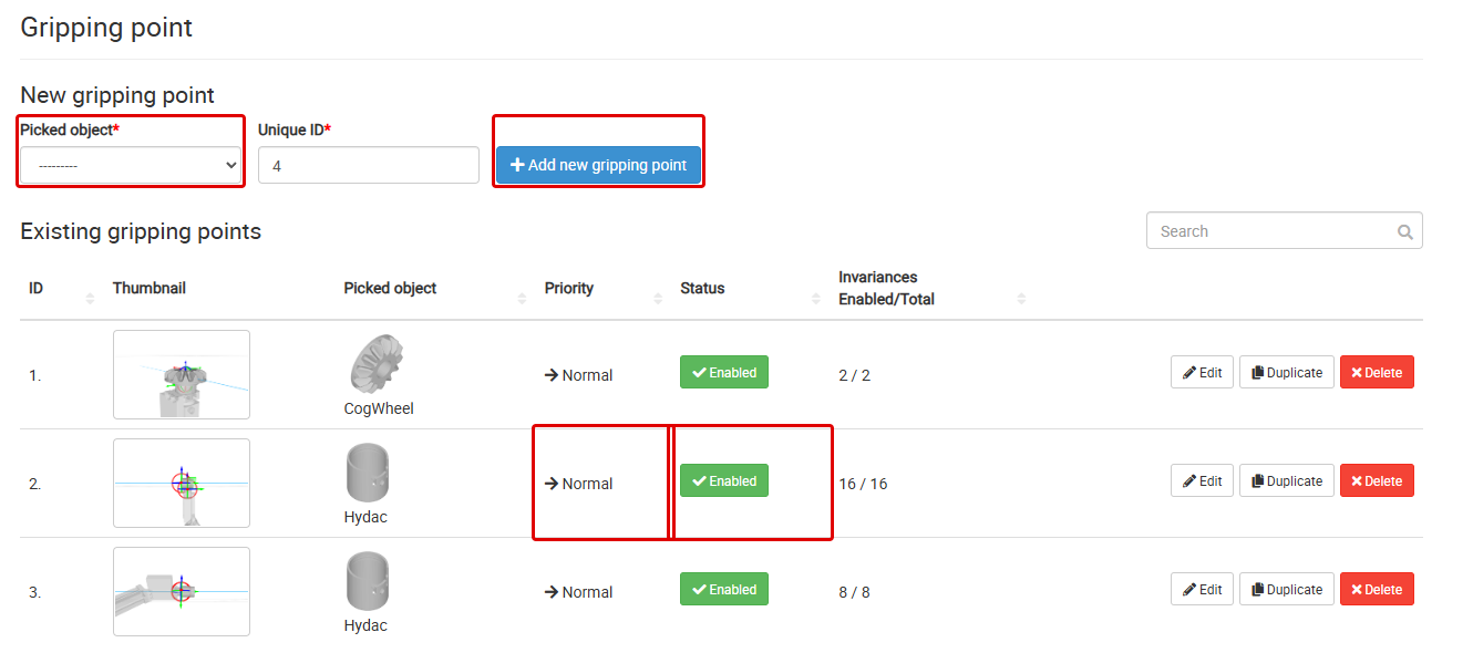
The Gripping point page of the CAD Picking example solution. Red frames: the Picked object of a new gripping point, Add new gripping point, and the Priority and Status of a gripping point.
To add a gripping point:
Select the Picked object the gripping point belongs to.
Check the Unique ID. The Studio fills in the next free number.
Click Add new gripping point, then set the gripping point in its form (see below).
The list of existing gripping points shows:
Column |
Description |
|---|---|
ID |
The unique ID of the gripping point. |
Thumbnail |
The gripping point on the picked object. |
Picked object |
The picked object the gripping point belongs to. |
Priority |
Low, Normal or High, see Priority. |
Status |
Enabled or disabled. Click the button to switch it. A disabled gripping point is not used for picking. |
Invariances Enabled/Total |
How many of the invariance steps are enabled, out of all steps. |
Each gripping point has an Edit, a Duplicate and a Delete button. Use Search to filter the list, and click a column title to sort it.
Gripping point form
Click Edit to open the form of a gripping point. The 3D viewer next to it shows the picked object, the gripping point and the gripper.
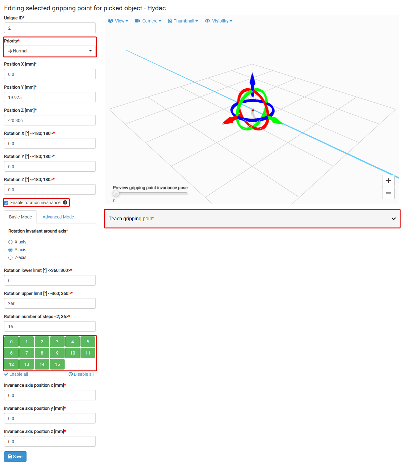
The form of a gripping point with 16 invariance steps. Red frames: Priority, Enable rotation invariance, the invariance steps and the Teach gripping point panel.
Field |
Description |
|---|---|
Unique ID |
The ID of the gripping point. |
Priority |
Low, Normal or High. |
Position X/Y/Z [mm] |
The position of the gripping point, relative to the origin of the picked object model. |
Rotation X/Y/Z [°] |
The orientation of the gripping point, each in the range -180 to 180. The Z-axis of the gripping point points into the object. |
Enable rotation invariance |
Creates more gripping poses by turning the gripping point around an axis, see below. |
Click Save to store the gripping point. You can also drag the marker of the gripping point in the 3D viewer.
Priority
The priority is used when the Picking priority method in the settings is Gripping Point Priority. Use separate gripping points when some grasps are better than others, and give the better ones a higher priority.
Rotation invariance
An invariance is a turn around an axis after which the object looks the same to the gripper. What invariances are and how to choose them is explained in Invariance above.
When Enable rotation invariance is selected, the Studio turns the gripping point around an axis in equal steps. Each step is one more pose the gripper can use.
Field |
Description |
|---|---|
Rotation invariant around axis (Basic Mode) |
The axis of the gripping point to turn around: X-axis, Y-axis or Z-axis. |
Rotation invar. axis X/Y/Z component (Advanced Mode) |
Any axis, as a direction vector. Each component is in the range -1 to 1. |
Rotation lower limit [°], Rotation upper limit [°] |
The range of the rotation, each in the range -360 to 360. The default is 0 to 360. |
Rotation number of steps |
How many poses the range is split into, 2 to 36. If the last step falls on the first one (for example 360° and 0°), they count as one. |
Step buttons |
One button per step, numbered from 0. Green steps are enabled. Click a step to disable it, for example when the gripper cannot grasp the object from that side. Enable all and Disable all switch all steps. |
Invariance axis position x/y/z [mm] |
A point the axis goes through, relative to the origin of the picked object model. Use it when the axis of symmetry does not go through the origin. |
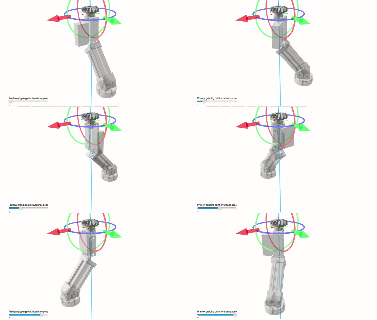
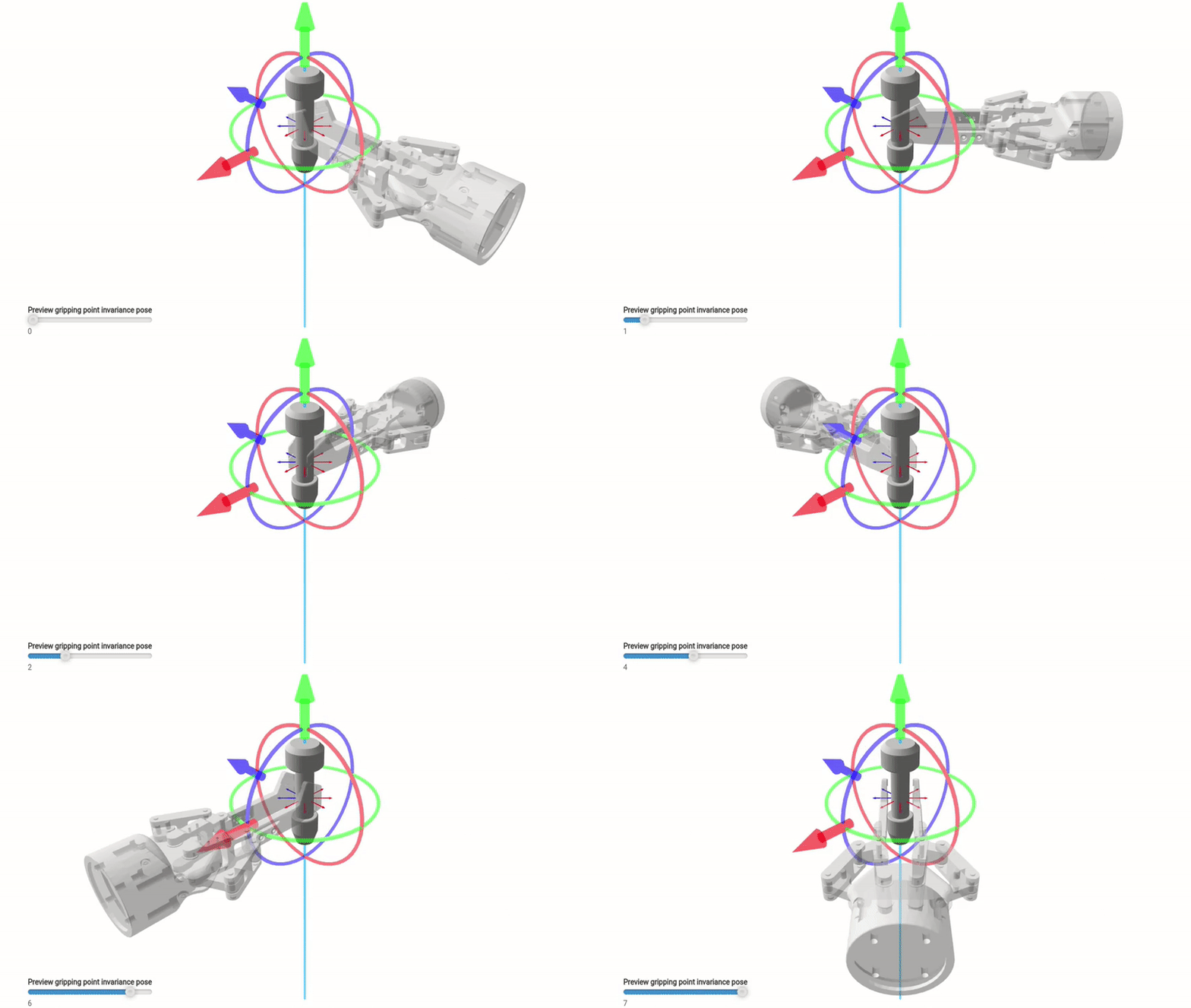
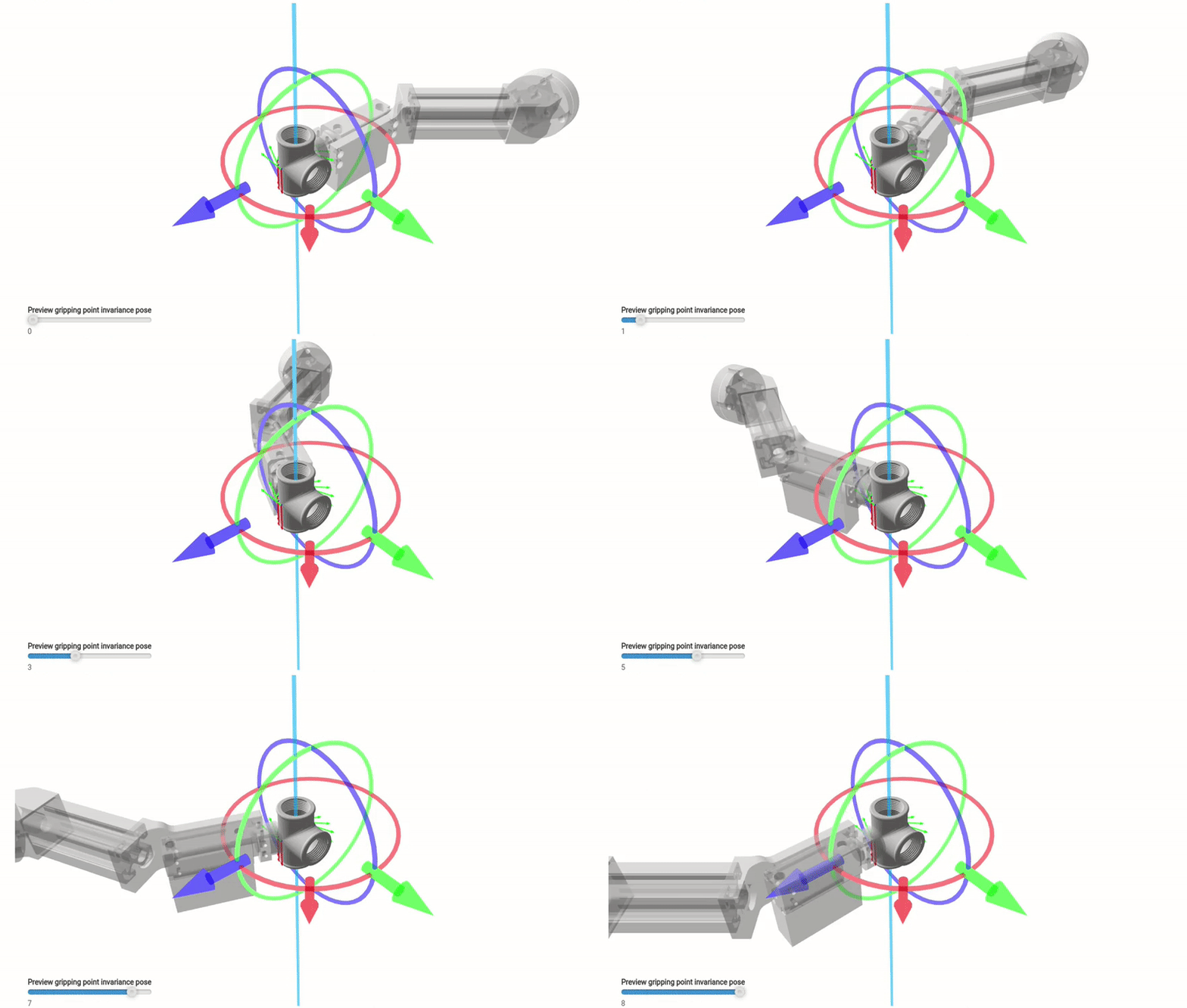
Use the Preview gripping point invariance pose slider in the 3D viewer to see the gripper in each pose.
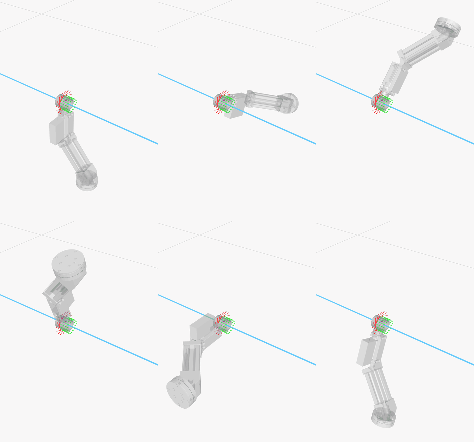
The preview of a gripping point on a cylindrical object, with 16 invariance steps around the axis of the cylinder (blue line). The animation steps through the slider of the Studio’s 3D viewer.
The gripper can also have its own invariance, set on its tool point. The two multiply: avoid invariances around the same axis on both, see Multiplying invariances.
Teaching a gripping point
Instead of typing the position and rotation of a gripping point, you can teach it with the real robot. You place an object in the cell and guide the robot so that the gripper grasps it the way you want. The Studio localizes the object and computes where the tool point is relative to the object. This pose becomes the gripping point.
Before you start
Teaching works only with a fully set-up cell. The Studio checks the selected vision system and disables Start teaching if something is missing:
Requirement |
Message of the Studio if it is not met |
|---|---|
The vision system has a localization profile |
“Selected vision system is missing the localization profile. Teaching gripping point is only supported for fully configured and calibrated vision systems.” |
The vision system has a robot-camera calibration |
“Selected vision system is missing the robot-camera calibration. Teaching gripping point is only supported for fully configured and calibrated vision systems.” |
The 3D sensor is not mounted on the robot arm |
“The sensor used by this vision system is mounted on the robotic arm. Teaching gripping point is not supported for this configuration.” |
In addition:
The Studio reads the current pose of the tool point from the Robot State Server, so the Robot module must be running on the robot controller and connected. The Studio shows the status of this connection during teaching. See Robot communication overview.
The gripper of the solution must have the correct tool point. The taught gripping point is computed from it.
Teaching uses the scanning profile of the vision system. The profile is uploaded to the 3D sensor when teaching starts. See 3D sensors and scanning profiles.
Teaching is not available in the cloud version of the Studio.
Teach gripping point panel
The Teach gripping point panel is below the 3D viewer of the gripping point form. Click its title to open it.
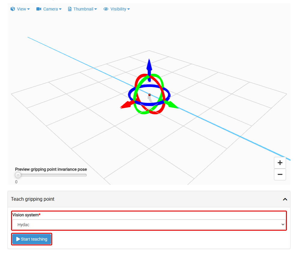
The opened Teach gripping point panel of the CAD Picking example solution. Red frames: the Vision system list and Start teaching.
Teaching step by step
Open the gripping point in the Gripping point step (click Edit, or add a new gripping point).
Open the Teach gripping point panel, select the Vision system and click Start teaching. The Studio starts the vision system, the same way as for a deployment, and the page reloads in teaching mode.
Place one object in the scene, where the 3D sensor can see it. Keep the robot out of the view of the sensor.
Start the scan. The Studio scans the scene and localizes the objects.
Move the robot with the teach pendant so that the gripper grasps the object exactly the way you want.
Reload the robot pose. The Studio reads the current pose of the tool point and fills the table of taught gripping points.
Click a row of the table. The Studio copies its position and rotation into the form, and the 3D viewer shows the gripping point on the model.
Finish teaching, check the gripping point in the 3D viewer and click Save.
Table of taught gripping points
The table has one row for each localized object. Each row is the pose of the tool point relative to that object:
X, Y, Z – the position in millimetres,
Rx, Ry, Rz – the rotation in degrees.
The rows are sorted by distance, so the object closest to the tool point comes first. This is normally the object the gripper is grasping. Use the up and down arrow keys to move between the rows.
If you move the robot again, reload the robot pose. The table is computed again for the same localization result, so you do not have to scan again.
Note
Teaching sets only the position and rotation of the gripping point. Set the Priority and the rotation invariance in the form as usual.
Tips
Use an object that the localization finds reliably, and check its pose in the 3D viewer before you move the robot.
Grasp the object carefully. Any offset between the gripper and the object is taught into the gripping point.
If you need several gripping points, teach each one in its own gripping point form.
Example tool points
The two most common grippers.
Two-finger gripper
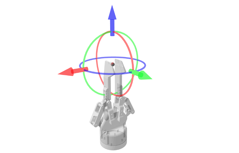
The tool point is between the fingertips (the red ball), right above the origin of the gripper model, so only a Z offset is needed.
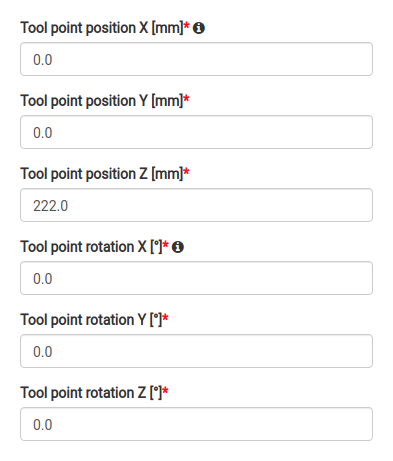
|
|
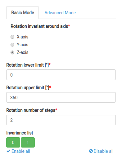
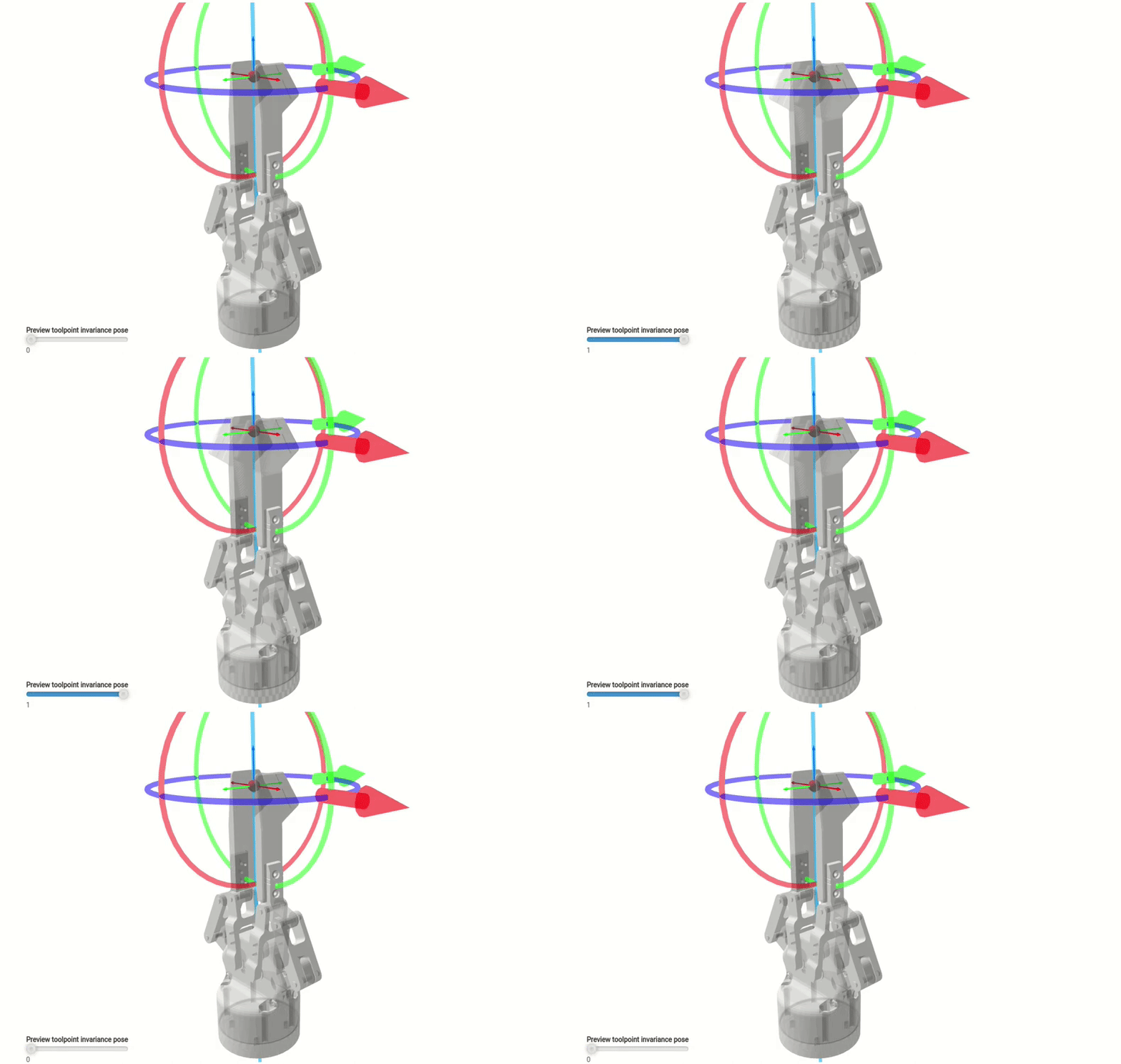
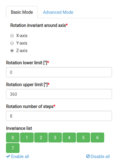
The gripper grasps the same way when turned by 180° around the Z-axis of the tool point (blue), so Rotation number of steps is 2. Preview the poses with the slider in the 3D viewer.
|
|
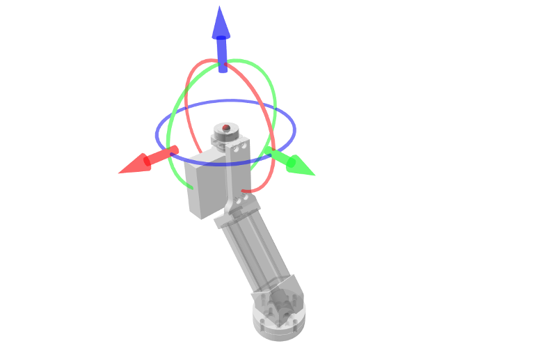
Magnetic gripper
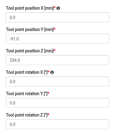
This magnetic gripper is shaped like a hockey stick. The tool point is in the middle of the magnet, so it is offset from the origin in both Z and Y.
|
|
The magnet is a flat round disc, so the grasp is the same at any turn around the Z-axis of the tool point (blue). More steps make path planning succeed more often, but too many slow down the picking. The default of 8 steps is a good choice here.
|
|
Note
The same applies to a gripper with one suction cup in place of the magnet.
Example gripping points
How to define gripping points for a few objects, depending on the gripper.
Cylinder with a two-finger gripper
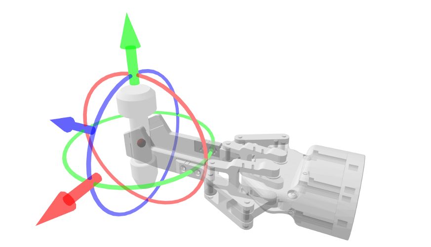
The best gripping point is in the middle of the object, on its axis of symmetry.

|
|
To grasp it from many angles, you could add more gripping points. It is simpler to use one gripping point with a rotation invariance around the Z-axis of the object. The default values are fine.

|
|
Gear with a magnetic gripper
A magnetic gripper needs a flat contact surface. This gear has two: the top and the bottom face. The gripping point is in the middle of the bottom face.
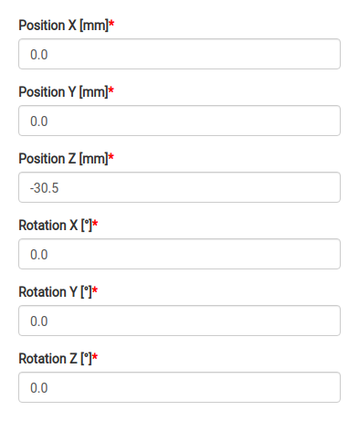
|
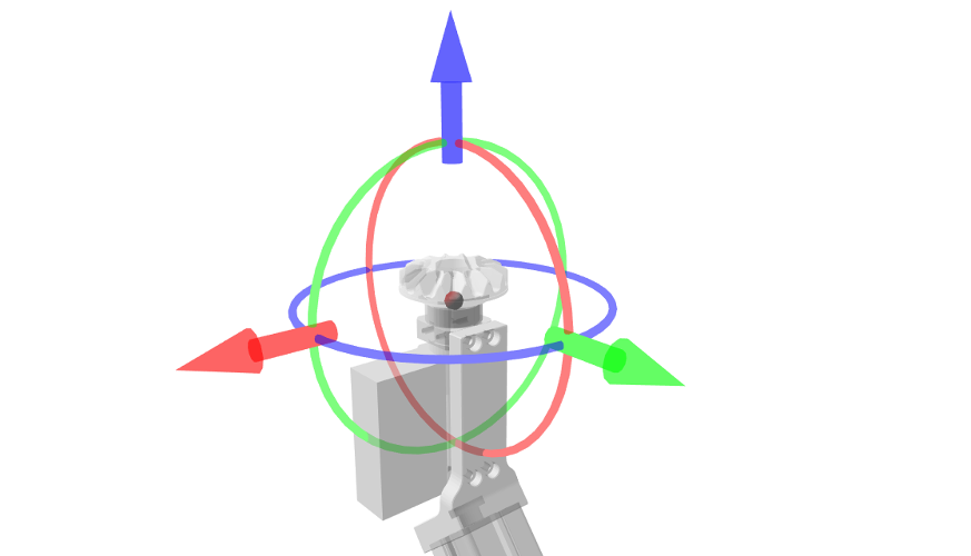
|
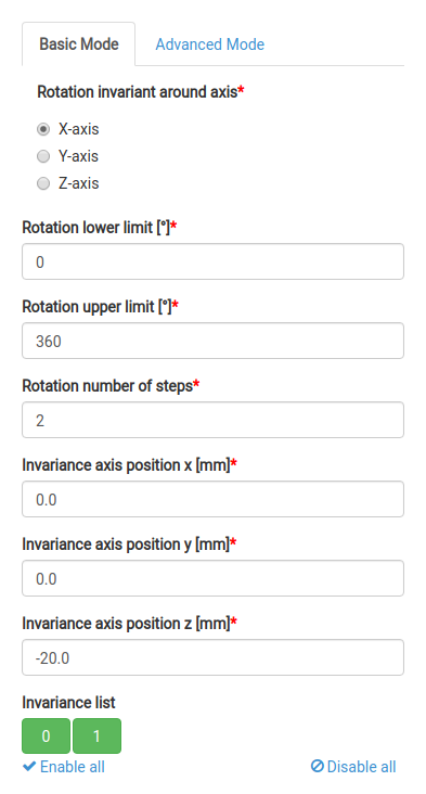
The gears lie in the bin in any orientation, so the top face is needed too. For the magnetic gripper the gear is symmetrical around its X and Y axes, so both faces can be one gripping point with two invariance steps, 180° apart:
Set Rotation number of steps to 2.
Move the Invariance axis position z to the centre of the gear. The default 0 is the origin of the model, which is on the bottom face.
Note
Do not add invariances around the Z-axis to this gripping point. The magnetic gripper is already invariant around the same axis, so they would only repeat grasps and slow down the computation.
|
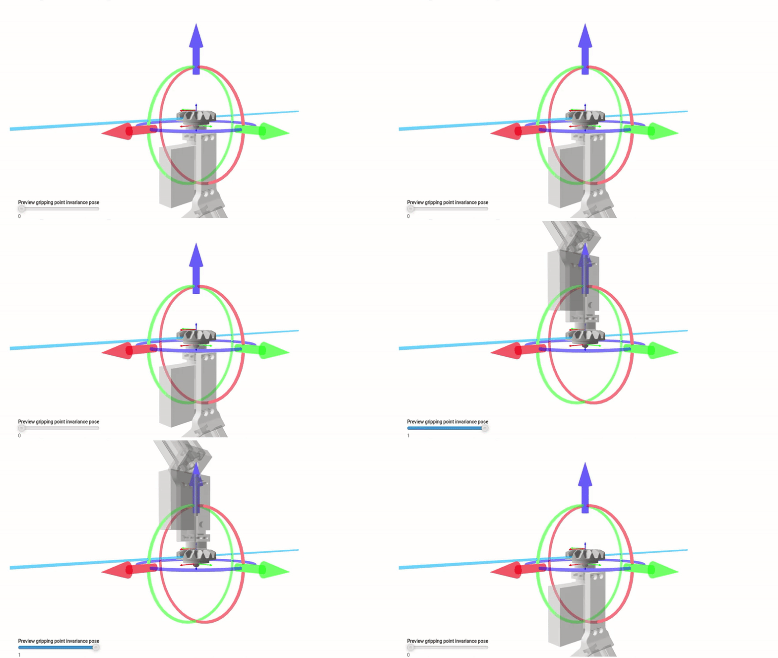
|
T-fitting with a magnetic gripper
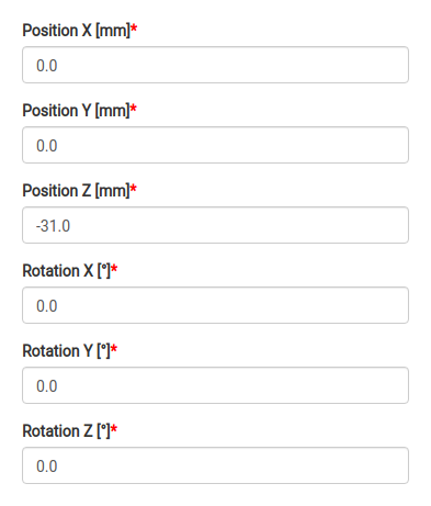
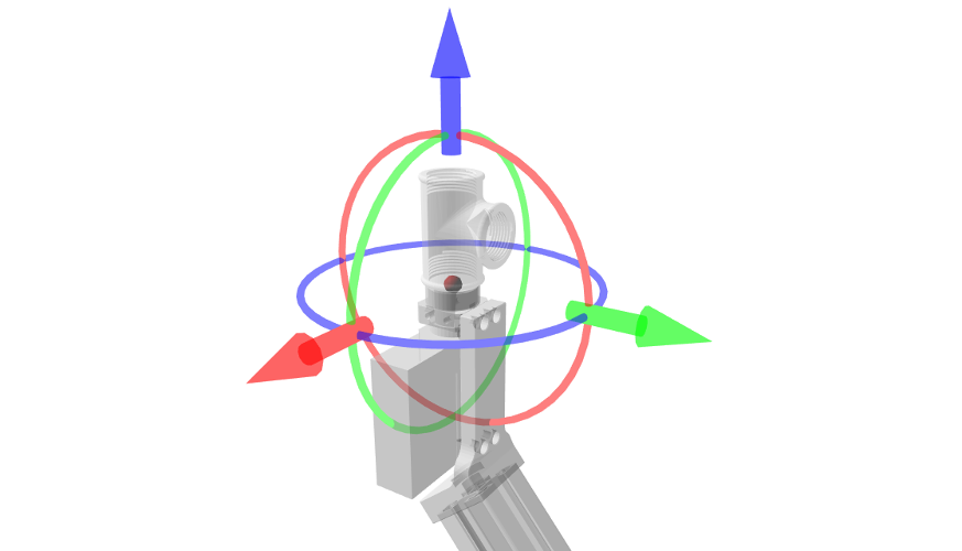
The three openings of a T-fitting have enough flat surface for a magnetic gripper. The first gripping point is in the middle of the bottom opening.
|
|
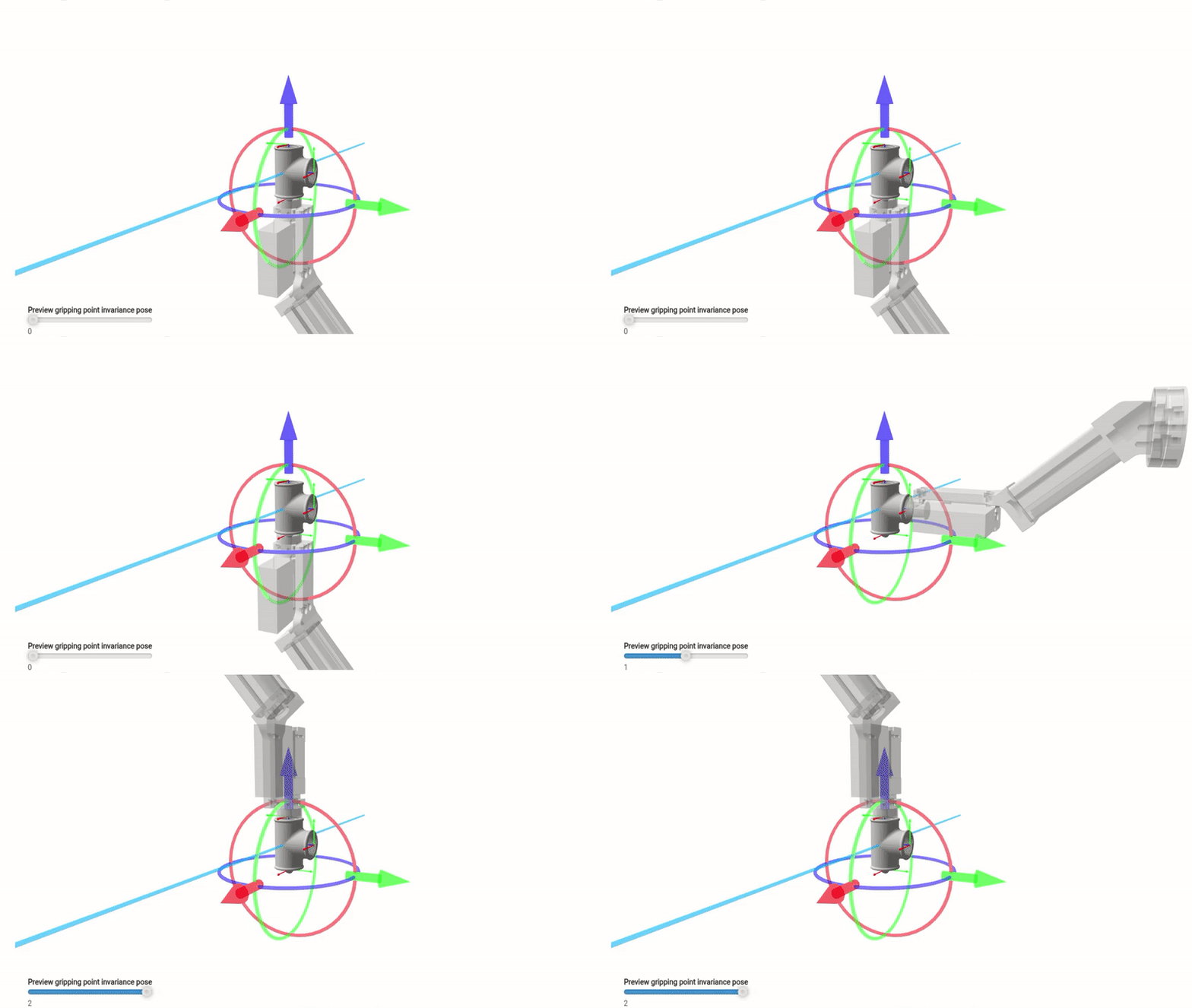
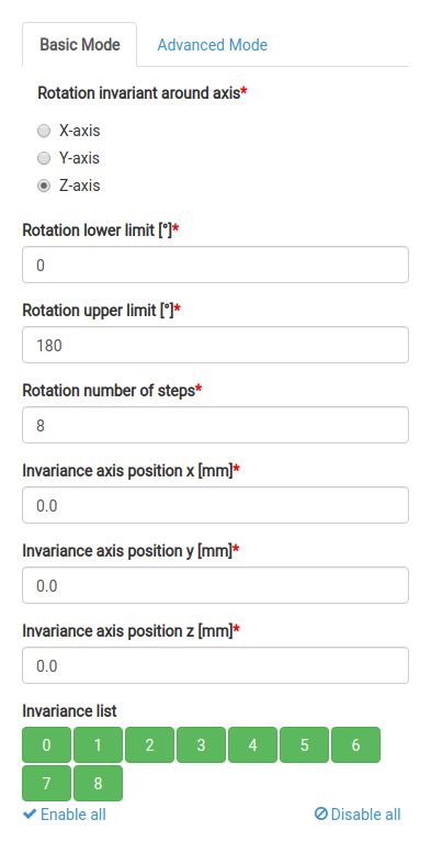
The openings are the same distance from the centre, so the object is partly symmetrical around its X-axis. It is not fully symmetrical, so limit the range: set Rotation upper limit to 180° and Rotation number of steps to 2. The origin of this model is in its centre, so the axis already goes through the right point.
Note
Do not add invariances around the Z-axis (blue) here, because the magnetic gripper is already invariant around it.
The same result: keep the full range 0–360° with 4 steps and disable the step on the wrong side of the object (for example step 3, at 270°). Both setups perform the same.

|
|
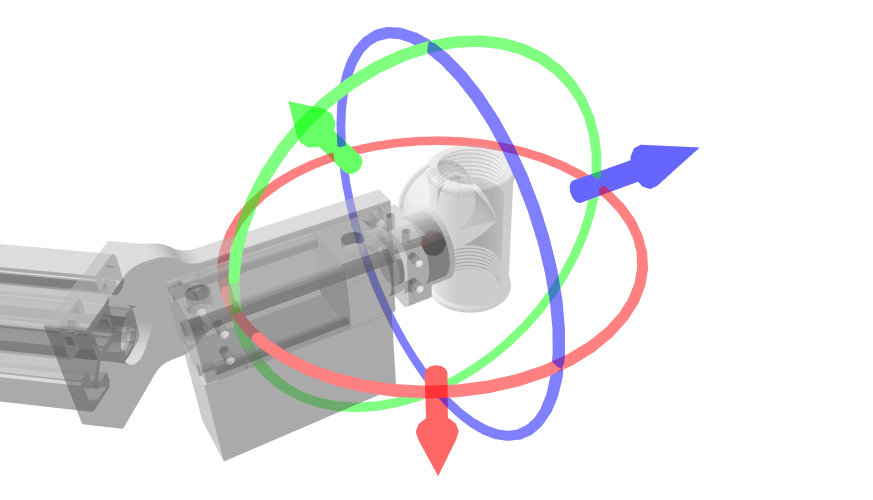
Objects in a bin lie in any orientation. When none of the three openings can be reached (they are hidden, at a bad angle, and so on), the object stays in the bin. There is no symmetry left to use on the first gripping point, so add a second gripping point:
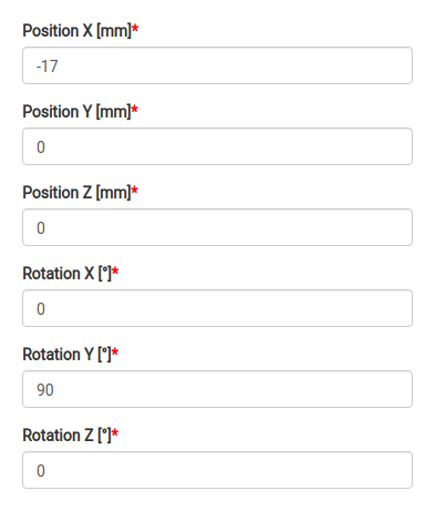
Its invariance axis goes through the two opposite openings (the X-axis here), perpendicular to the axis of the first gripping point.
It is offset so that it lies on the surface of the object.
|
|
This gripping point is again only partly invariant around the X-axis: exclude the angles where the middle opening is. Either set Rotation upper limit to 180°, or disable the steps where the gripper would hit the middle opening. Both perform the same.
|
|
Oriented placing
When a bin picking trajectory is received, alongside it additional data are transferred to the robot controller that can be used for the oriented placing of the picked object. These data describe the exact configuration of the tool point and gripping point used for grasping the picked object. By defining a placing procedure for every possible grasping configuration it is possible to achieve the oriented placing of objects.

A non-symmetric bracket has one gripping point with 4 rotation invariance steps (every 90°), so the robot can grasp it turned in 4 ways. With the trajectory, BPS reports which step was used. Without oriented placing, the robot program uses the same placing pose for every grasp, and the bracket arrives turned and does not fit the nest. With oriented placing, the robot program turns the placing pose by the reported step × 90°, and every bracket fits. The blue tab shows the orientation of the gripper.
Variables
A grasping configuration is defined by 3 variables (placing data):
Tool point invariance The invariance of the tool point used for grasping the picked object. If the tool point invariance is disabled, the value is always 0.
Gripping point ID The ID of the gripping point used for grasping the picked object.
Gripping point invariance The gripping point invariance used for grasping the picked object. If the gripping point invariance is disabled, the value is always 0.
When the tool point has 2 invariances and 3 gripping points are defined for a picked object with each having 4 invariances, there is a total of 2 x 3 x 4 = 24 possible grasping configurations.
These placing data (variables) are received with the bin picking trajectory when the procedure Receive trajectory is successful. See the description of the procedure inside the integration guide for a particular robot brand to see how to access the placing data.
Best practices
It is necessary to teach a placing position for every grasping configuration. However, any change in the definition of the tool point / gripping points will render those taught positions invalid. If possible, it is recommended to teach only the minimum required base positions and use the received placing data to calculate the final transformation (offsetting).
Note: For a cylindrical object with a gripping point lying on the axis of the object’s symmetry (example), it is necessary to have the invariances enabled to be able to grasp the object from multiple sides. However, the chosen invariance is not relevant and it is sufficient to use a single placing position for all invariances of the gripping point.
Tip: To force a gripping point (or its invariance) to be used for the purpose of teaching a placing position, temporarily disable the rest of the gripping points (invariances). The same applies to tool point invariances.