Integration Guide KUKA KRC LS 1.5
Integration guide for KUKA KRC Robots with Locator Studio version LS 1.5.
1. Robot Controller Setup
1.1 Initial Setup and Configuration
The KRC controller is equipped with several Ethernet ports, each designated for a specific purpose. For communication with external devices such as a PC or a vision controller, the recommended interface is the KUKA Line Interface (KLI).
While the exact layout can vary slightly between different KRC4 models (e.g., compact vs. standard), the KLI port is almost always externally accessible. In our controller, the KLI port is located on the rear side of the KRC4 cabinet door as shown in the figure below. From here it is usually routed to either the main connection panel at the bottom of the controller or upper cabinet door outlets. Track down where the cable leads and plug your Ethernet cable to appropriate outlet. In some configurations, the internal motherboard’s LAN port is routed to this external X66 connector.
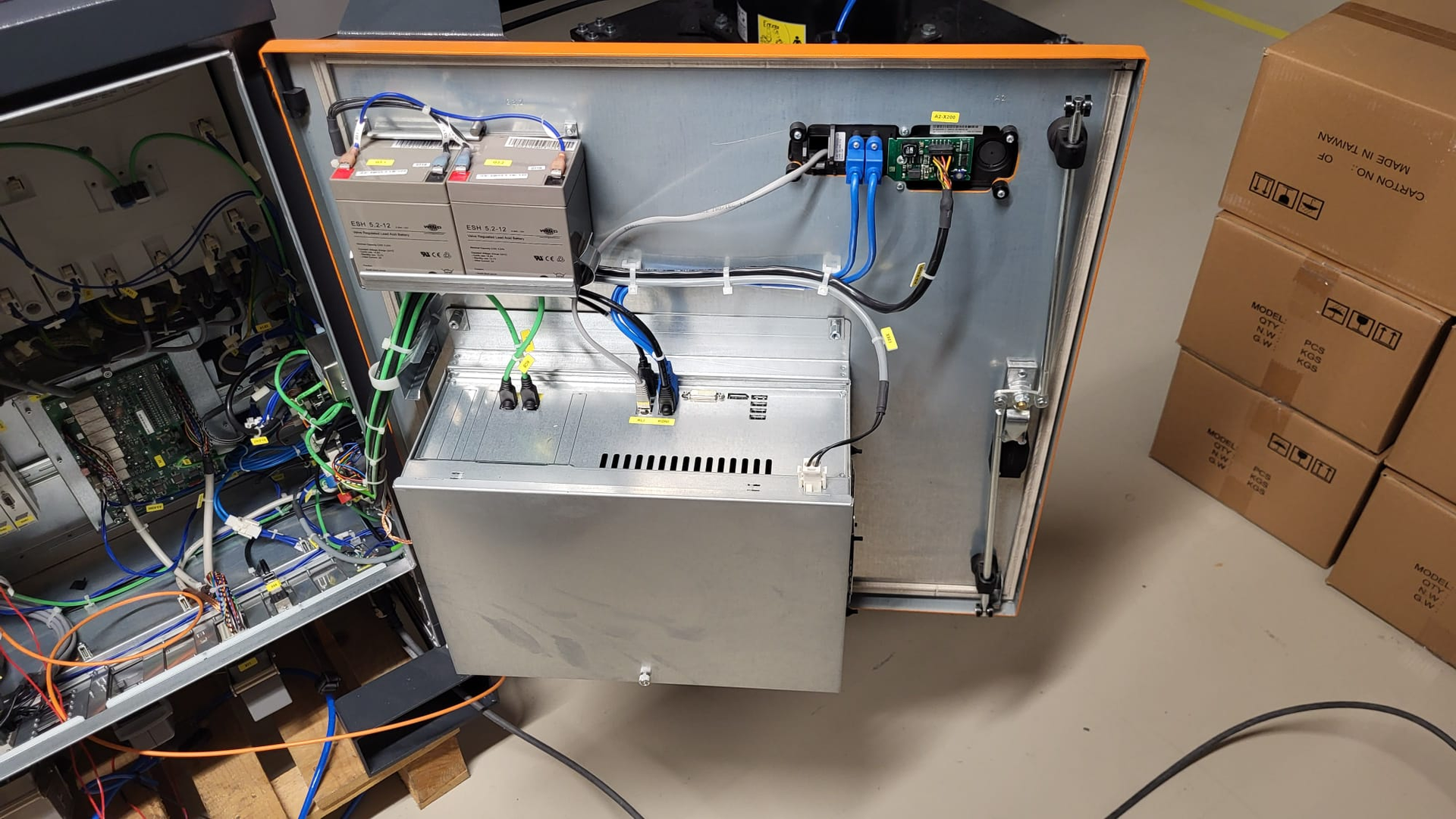
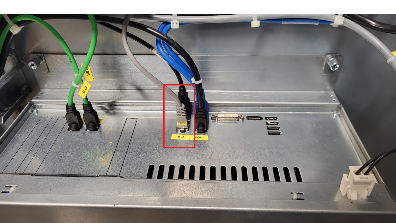
Connect KLI port either directly to the Robot port on the vision controller or through a network switch for more complex network setups.
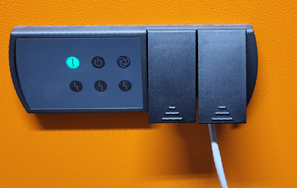
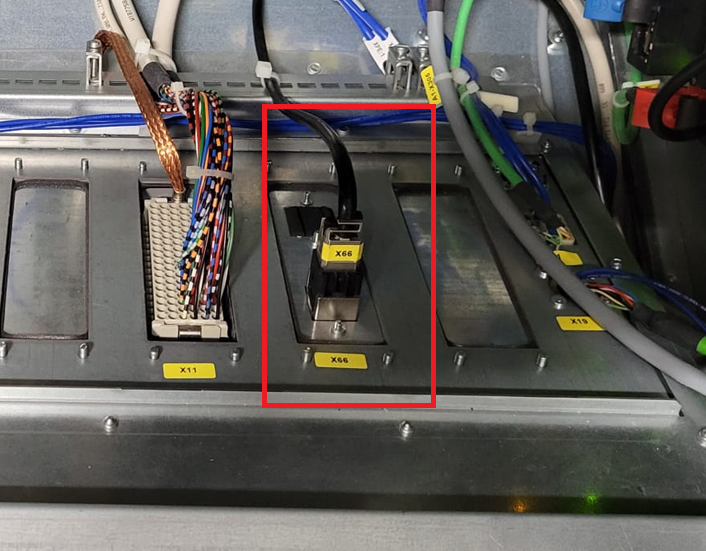
In next step we will follow up with Network configuration of KUKA robot controller
1.2 Network Configuration
Photoneo KUKA Module utilizes TCP/IP communication for transferring data between KRC Robot Controller and Locator Studio.
As the first step in commissioning, ensure that the IP address of the KRC controller meets your network configuration requirements.
Switch to Expert Mode, open the Menu screen and select the Startup-> Network Configuration option:

Select Fixed IP Address as the network method and type IP address and Subnet Mask for Robot Controller. Configuration used in this manual is 192.168.1.2 and 255.255.255.0.
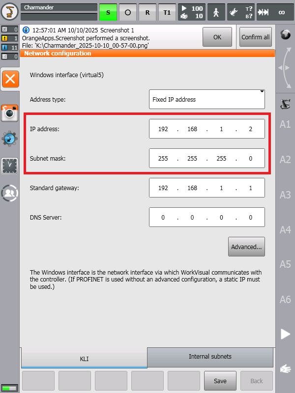
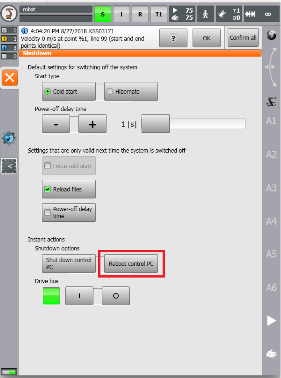
Click the Save button to confirm the changes. KRC Control PC needs to be rebooted in order to apply the new network configuration.
Open the Menu Screen and select the Shutdown -> Reboot control PC option:
Note
Subnet Mask 255.255.255.0 equals 24 bit subnet mask representation. See this table for more combinations: https://dnsmadeeasy.com/support/subnet
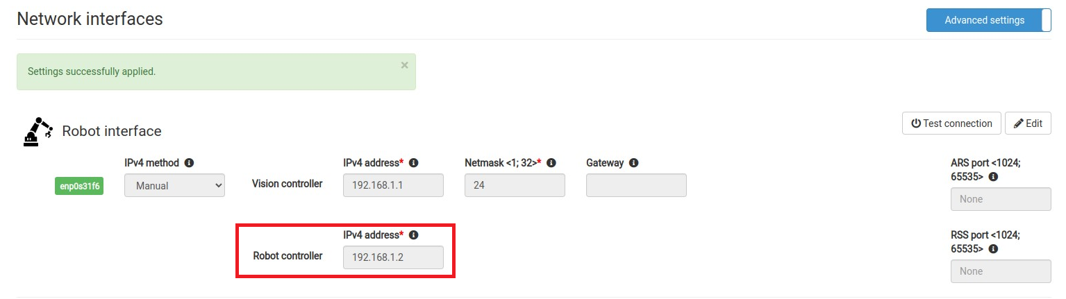
An example of matching Network configuration on Vision Controller side
Vision Controller IPv4 Address: 192.168.1.1 / 24
Robot Controller IPv4 Address: 192.168.1.2 / 24 (as configured in the previous step)
You can also use Test Connection button on Photoneo Vision Controller Network page to ping KUKA Robot Controller from Photoneo Vision Controller
Based on the result of Test Connection (ping command) you will get a Robot Available or Robot Unavailable message pop up. If the robot is unavailable, double check cabling and network configuration.

1.3 Importing Photoneo KUKA module
List of files that comprise Photoneo LS KUKA module version 1.5
Ethernet KRL XML files:
Photoneo System files:
|
Photoneo Template files:
|
There are three default options how to transfer Photoneo KUKA module to robot controller:
Copy KOP (KUKA Option Package) using USB Flash Drive - ideal for first time installations of the entire module quickly
Copy individual files using USB Flash drive - ideal for situation where you need to manipulate with individual files for instance updating module version without losing already working programs
Using Work Visual - most advanced option for KUKA professionals
1.3.1 Using KUKA Option Package
KUKA Option packages are software add-ons that provide additional functionalities and simplify integration within the KUKA robotics ecosystem. For the Photoneo KUKA interface it means that KOP allows you to install all module files at once and have them automatically copied to proper locations even including Ethernet KRL XML files.
The easiest way to install the Photoneo KUKA module on a robot controller is to copy the Photoneo KUKA Option Package from USB Flash Drive to KUKA KRC Controller and install it directly.
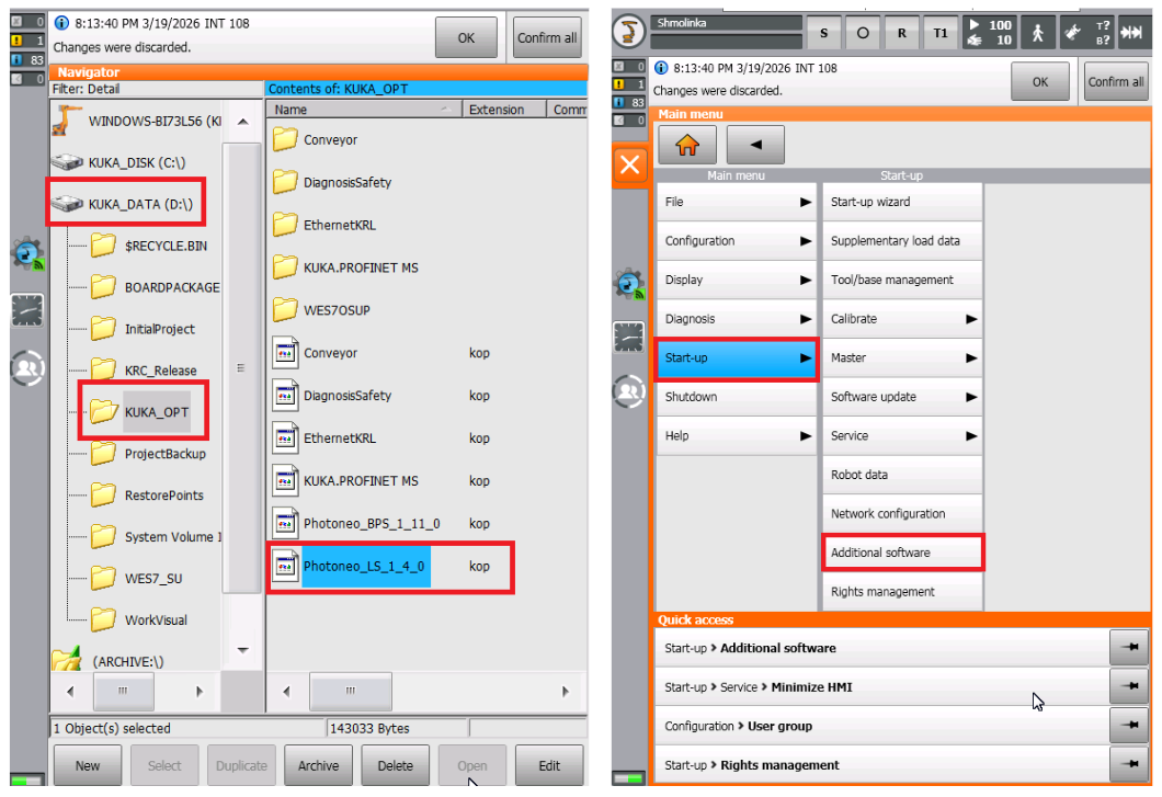
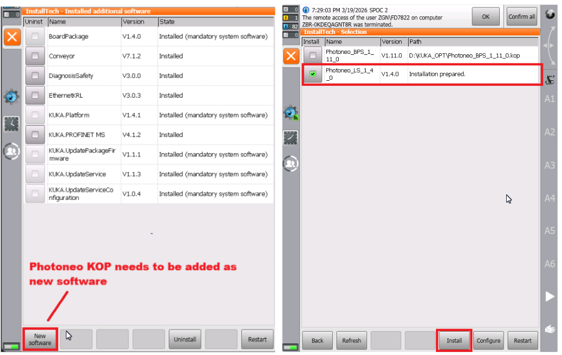
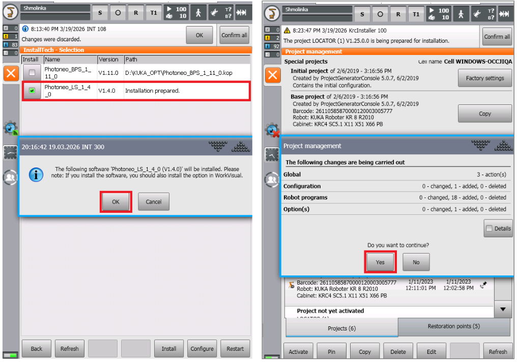
By default Photoneo_LS_1_5_0.kop will not be in the list, it needs to be added as a new software using the bottom button New Software as shown below. Clicking this button will open the InstallTech selection window where Photoneo_LS_1_5_0.kop should be visible in the list. Hit the checkbox on the left and click Install button.
Photoneo_LS_1_5_0.kop will be installed on the robot controller, a message popup with the amount of files being added to the system will be shown. Just confirm “Yes” and finish the installation.
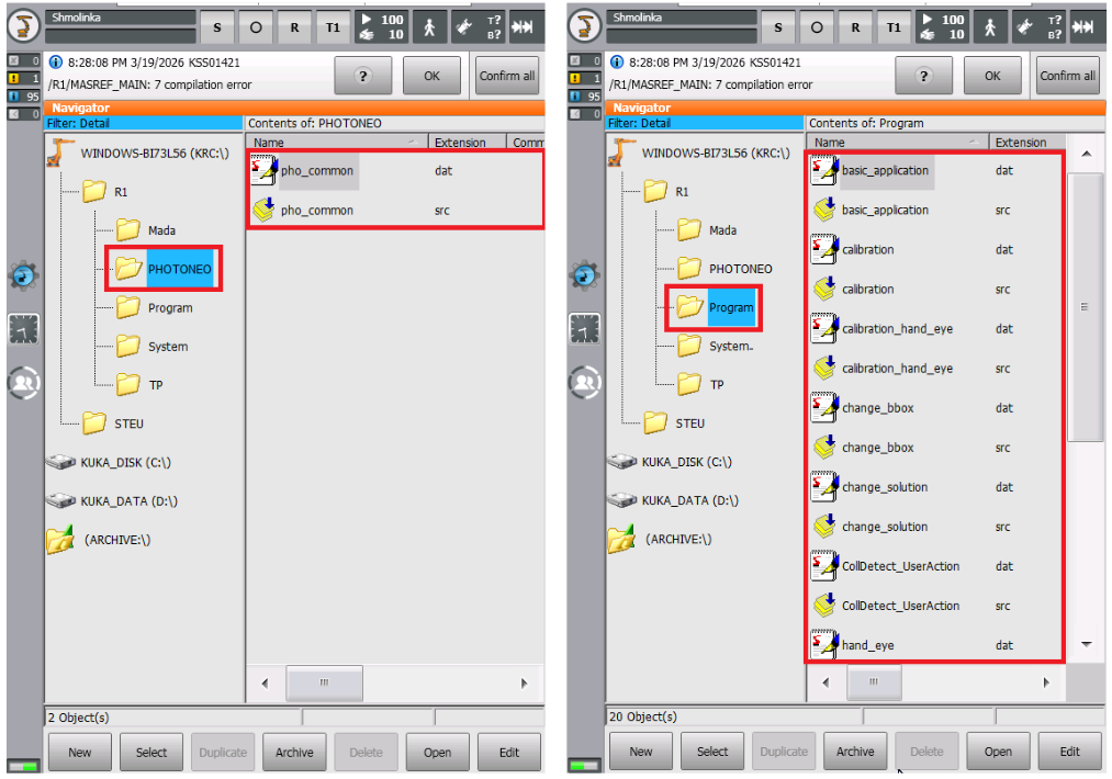
After installing KOP, Photoneo files will be added to R1 folder - notice PHOTONEO folder with system files and example program templates are added to Program folder:
EthernetKRL XML file is also added to filepath:C:KRCRoboterConfigUserCommonEthernetKRL
1.3.2 Copying files using USB Drive
Another method of transferring files to the KUKA KRC controller is to use a USB Flash drive and copy files directly using Edit and Copy buttons. This method is useful for situations where manipulation with individual files is needed. For example updating a version of a module where only pho_common.src and pho_common.dat usually needs to be replaced and using KOP might break existing programs.
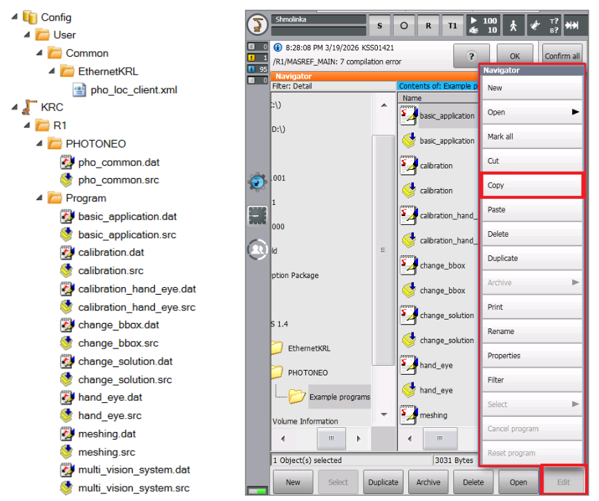
When copying files individually make sure you follow the recommended structure of how files should be organized shown in the picture above. The location of EthernetKRL is critical and must match the original requirements.
1.3.3 Using Work Visual
For the most convenient work with the Photoneo-KUKA interface, a remote connection from a PC to the robot controller using KUKA Work Visual SW is recommended. KUKA Work Visual software can be downloaded free of charge from the official KUKA website.
Using an ethernet switch to fork robot KLI connection or using a Robot Service Ethernet port X43 or X66 is necessary. Make sure your PC is on the same subnet as the robot controller interface and launch the KUKA Work Visual application on your PC.
Open KUKA Work Visual and in Workspace selection go to Programming and diagnosis. Then create a connection to the real robot controller using the Create connection button.
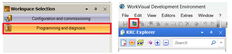
The following window pop up will show up, and if the robot is reachable on the network it should be visible in the list as shown below. Click OK to establish connection and download current file structure from the robot to Work Visual:

After connecting to the robot, click on the robot name with the right mouse button and use the Open in Windows Explorer option to open the folder where project files are stored. This is usually in on filepath: C:Usersyour_usernameDocumentsWorkVisual 6.0RepositoriesRobot_NameKRC:
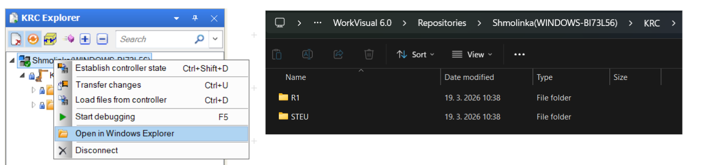
From here you can use File Explorer or Total Commander or other tools to copy Photoneo files directly to this project structure folder. When ready, transfer files to the robot controller using the Transfer Changes button available when clicking the right mouse button on the robot name. List of all changed files will show up, click OK to start transfer.
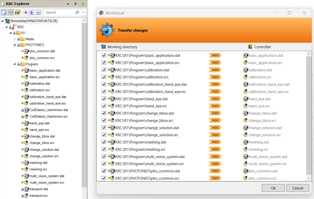
For transferring EthernetKRL files, just copy XLM files to Photoneo folder through Work Visual and then manually copy them to C:KRCRoboterConfigUserCommonEthernetKRLusing Edit and Copy buttons directly on Pendant. An alternative is direct modification of Robot Config through Work Visual Configuration and Commissioning Workspace.
1.4 Ethernet KRL configuration
The EthernetKRL Config folder contains one XML file - pho_loc_client.xml. This file must be copied to following filepath: C:KRCRoboterConfigUserCommonEthernetKRL
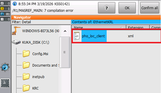
XML file contains the configuration of the EKI communication interface. The only entry that needs to be changed is the IP address tags.
Enter the IP address of the Vision Controller to External IP tag in pho_loc_client.xml as is shown in the figure below. Do not change the default port value 54601 for pho_loc_client.
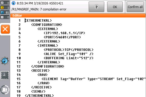
Save the changes and reboot the control PC again to apply the new EthernetKRL configuration:
1.5 Tool TCP Setup
For Locator Studio, tool setup is more important than for Bin Picking Studio which is designed to operate with a zeroed tool and compensate for offset programmatically. General rule of thumb for Locator Studio is that all scanning and calibration must be done in $NULLFRAME frame, while all picking must be performed with a real tool - for the purpose of this tutorial we will be using tool named “CustomTool” with Z offset Z = 205mm.
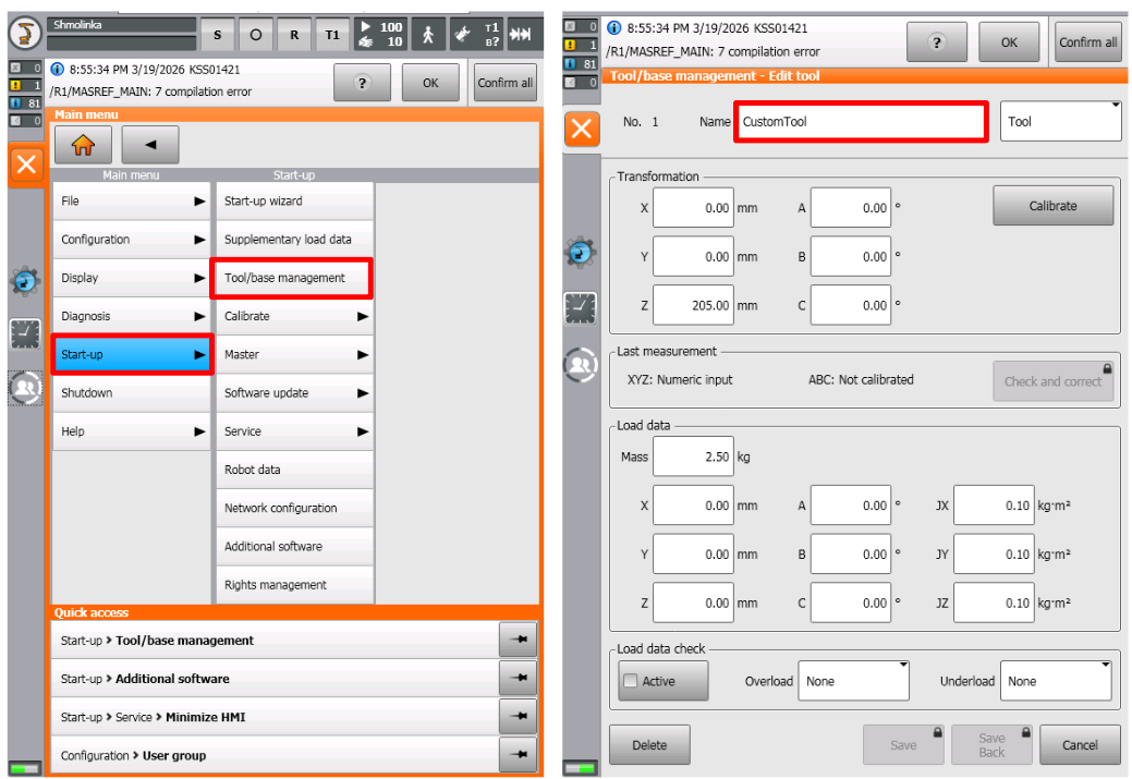
Change of TCP is recommended whenever it is necessary to force use of the proper tool frame. For example for scan and calibration requests, we always need “$NULLFRAME” but when picking based on the result of Get Object Pose, “1 Custom Tool” needs to be selected.
1.6 How to use Photoneo KUKA Module
The Photoneo KUKA interface was developed as a set of ‘user frontend’ and the ‘communication backend’ programs. Files as pho_common.src serves as a communication backend while templates in example_programs are designed to be quickly deployed and easily modified by the user.
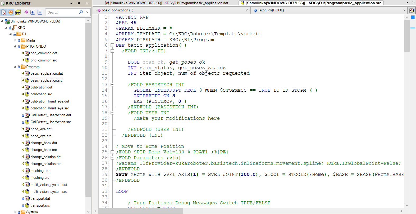
The basic_application.src provides a very simple example for executing Cartesian based picking sequences. It demonstrates the essential workflow: connecting to Locator Studio, triggering a scan, requesting a trajectory, and executing the subsequent pick-and-place operation. Other templates (multi_vision_systems, change_environment, change_solutions, change_bbox) are built on top of basic_application.src with some extra request calls demonstrating various features.
If you followed the steps described in section 1.3.3, you should already have WorkVisual connection and project deployed on your controller. Open basic_application.src to review the code. If your solution on Photoneo Vision Controller is ready, all that is missing is to touch up Home, Start, End + placing positions P1, P2, P3, and this program is ready to be deployed. The Runtime section provides all necessary details for final modifications.
Important
These templates are designed to work instantly, but you must make sure the feature you want to use is already set up and active in Locator Studio first. So for example if you want to test Change Bounding Box functionality, you need to have at least 2 bounding boxes configured in your solution.
2. Robot Module
Note
It is strongly recommended to read the Photoneo robotic API prior to this section (user login: customer password: Ready2LearnHow2Pick).
2.1 Connection to Photoneo Vision Controller
Note
Establishment of connection to the Action Request Server running on the Vision Controller side happens at the beginning of the program through the PHO_ConnectToVc() function.
The PHO_ConnectToVC() function activates the Ethernet KRL communication channel configured through EKI XML files in , therefore there is no IP address or a port here to set directly.
Requests can be sent to the Vision Controller only after a connection has been established. Successful connection is visualized by green Connected indicators on Deployment page after program on KUKA side is started, see image below

2.2 Request List
This section describes available API calls provided by the Robot module. These procedures are intended for high-level control of the locator application.
Note
These procedures are defined in the communication backend and must not be edited!
Request |
ID |
Definition |
Input |
Populates |
|---|---|---|---|---|
Calibration Start |
25 |
PHO_RequestCalibStart |
solution_id(global) vision_system_id(global) |
error_code |
Calibration Add Point |
5 |
PHO_RequestCalibAdd |
None |
error_code |
Calibration Save |
27 |
PHO_RequestCalibSave |
None |
error_code, calib_error_um, calib_pose |
Calibration Stop |
26 |
PHO_RequestCalibStop |
None |
error_code |
Scan Regular |
19 |
PHO_RequestScan |
vision_system_id(global) |
error_code (updated via PHO_WaitForScan) |
Scan Meshing (Capture) |
30 |
PHO_RequestCapture |
vision_system_id(global) |
error_code |
Reuse Scan |
31 |
PHO_ReuseScan |
vision_system_id(global) |
error_code |
Get Poses |
20 |
PHO_RequestGetPoses |
vision_system_id(global), num_of_req_targets |
error_code, object_poses, num_of_objects_received, dimension_x, dimension_y, rot_z_angle_deg, max_z_height, tilt_angle_deg, nn_label |
Get Vision System Status |
22 |
PHO_RequestGetStatus |
vision_system_id(global) |
error_code, num_of_localized_objects, num_of_ready_objects, vs_still_processing |
Change Bounding Box |
33 |
PHO_RequestChangeBBox |
vision_system_id(global), bbox_id |
error_code |
Change Solution |
9 |
PHO_RequestChangeSol |
solution_id(global) |
error_code |
Start Solution |
10 |
PHO_RequestStartSol |
solution_id(global) |
error_code |
Stop Solution |
11 |
PHO_RequestStopSol |
None |
error_code |
Get Running Solution |
12 |
PHO_RequestGetRunningSol |
None |
error_code, running_sol_id |
2.3 Example Programs
There are several KUKA program templates available in Photoneo KUKA module that demonstrate how to properly use requests listed in this section for various use cases:
KUKA Program Example |
Description |
|---|---|
|
This simple example demonstrates the basic workflow: it shows how to connect to the vision controller, trigger a scan request, wait for the scan to finish, request object poses, receive them, and execute picks. It also illustrates error handling for the |
|
Same as basic_application, but configured for a hand-eye setup ( |
|
These examples demonstrate the hand-eye calibration procedures for both static and robot-mounted camera configurations. Things to know:
|
|
Same as basic_application, but illustrates switching between two Vision Systems. The |
|
Same as basic_application but includes solution-switching logic. It demonstrates how to use |
|
Same as basic_application but includes bounding box-switching logic. Demonstrates how to dynamically switch between different Bounding Boxes using the |
|
Same as photoneo_basic, but with multiple get_status request calls. The |
|
Dynamic meshing example. This setup leverages the integration of Photoneo Instant Meshing technology alongside the Parallel structured light technique provided by Motion Cam 3D. Note that Dynamic Meshing cannot be utilized with standard PhoXi 3D Scanners. Procedure
Recommendations:
The total number of scans should not exceed 60 to maintain optimal performance. |
3. Runtime
Once the solution is fully configured on the Vision Controller side, it is time to finalize the remaining steps on the robot side and proceed to executing the basic_application.src program
3.1 Teach Positions
After opening basic_application.src or another template, there are a few local poses (HOME, START) that need to be touched up before running the program.


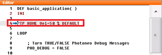
Select basic_application.src program, click on SPTP Home line and click Block Selection button at the bottom menu bar. Jog robot to new Home position (Should be out of scanning volume for static scanner mount) and click on Touch Up Button. Repeat with other local poses in the program.

Note
Approach and Deapproach poses are calculated automatically, just configure Z offsets in the code - default example uses 200mm Z offset for approach and 300mm Z offset for deapproach.
3.2 Gripper commands
Gripper commands are left completely up to the user to define and use properly for attaching and releasing parts in correct moments.
3.3 Runtime Prerequisites
Final pre deployment check before running Locator Studio KUKA interface from the robot side
Make sure that:
Locator Studio solution is properly configured on the Vision Controller side
Network Setup on Robot Side is completed
All Vision Systems defined in solution are calibrated
All local poses in main program have been touched up properly
Gripper procedures are prepared and working
3.4 Running basic_application.src KUKA program template
Deploy your solution. The Action Request Client (Robot) status on the Deployment page should be DISCONNECTED – if the communication hasn’t been established yet.

Note
It is strongly recommended to decrease the override speed to 10% before running the program for the first time.
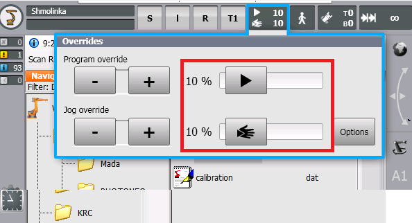
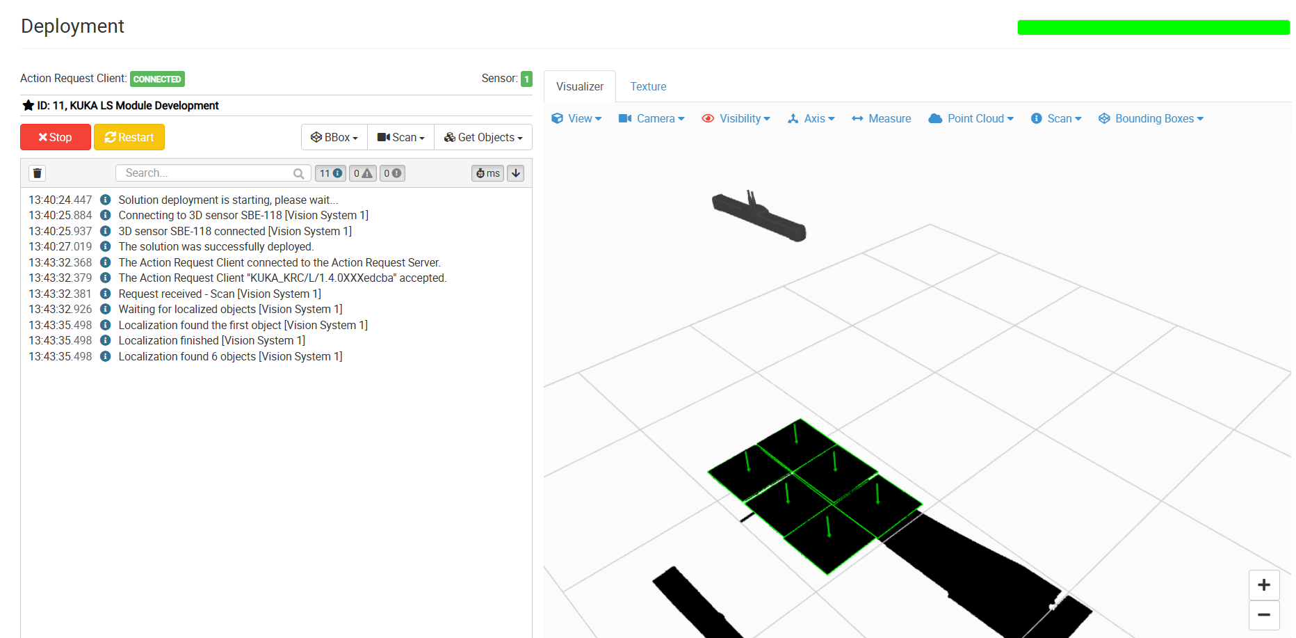
If connection has been established properly you will see Action Request Client status turn to CONNECTED. At this point the sensor should capture the first scan and localization should start localizing objects.

If there is a pickable object in the scene and the Cartesian Pose for this object has been received by the robot controller, the robot should start moving towards the first object.
If everything looks fine, keep moving the robot towards the first target and check if the path is correct. At this point if the robot is too far from the object or pushes the object too deep, or approaches object in wrong orientation, then make modifications to object origin on LS side or tool TCP setup on robot side. Tool calibration might be needed to get to proper picking state.
If robot movement looks fine, set up your own placing routine and slowly ramp up speed up to 100%
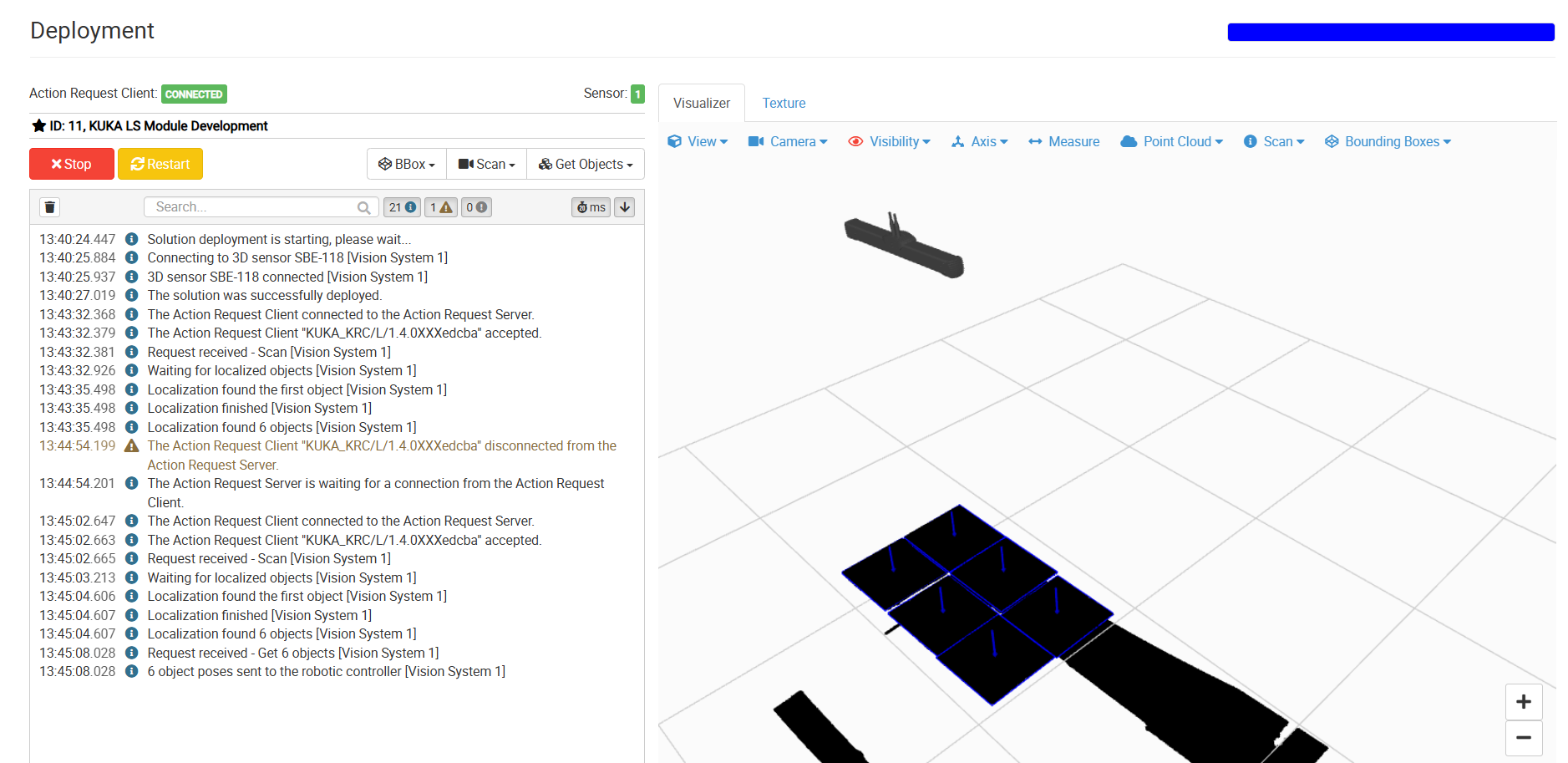
Congratulations, you have successfully deployed Photoneo KUKA Interface. You can now focus on improving your application further. Use CheatSheet and Program Templates as your guidelines.