Deployment page
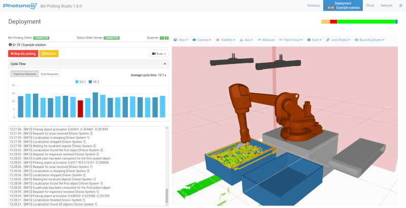
Once a solution is fully configured, it can be deployed - your bin picking application can be started. There are three ways to deploy a solution:
from the Solutions page, by clicking the Ready flag of the solution in the solution list
by clicking the Deployment shortcut at the bottom of the solution configuration wizard
From the Deployment page, by selecting the solution from the list of solutions ready for deployment
Contents
1 Deployment modes
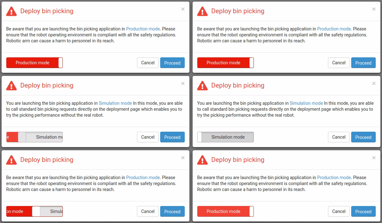
Note: Hand-eye vision systems depend on the data from the Robot State Server. Therefore, when using hand-eye vision systems in the Simulation mode, the real robot must be connected.
2 Hardware diagnostics
The Deployment page provides diagnostic information about the status of the connection to the hardware components of the bin picking application connected to the vision controller - the robot and sensor(s). There are three connection status indicators, two relating to the robot communication and one providing the connection status of sensors used in the solution’s vision systems. You can read more about robot communication in the Robot communication overview.
Action Request Client - status of the connection between the Action Request Server and Action Request Client (the Action Request Communication Channel). It can be in two different states:
** CONNECTED ** - the Action Request Client is connected to the Action Request Server and can send requests.
** DISCONNECTED ** - the Action Request Client is not connected to the Action Request Server, the server is waiting for a new connection.
Robot State Server - status of the connection between the Robot State Server and the Robot State Client (the Robot State Communication Channel). It can be in two different states:
** CONNECTED ** - the Robot State Client is connected to the Robot State Server and periodically receives robot state data - current joint positions and TCP pose.
** DISCONNECTED ** - the Robot State Client is not connected to Robot State Server, the client repeatedly tries to connect to the server.
If you are encountering issues with the robot communication or connection of the sensor(s), please check the troubleshooting guide.
3 Deployment action request toolbar
Initialization - to initialize a vision system with start and end poses of the bin picking routine
Change scene state - to change the current virtual model of the environment
Change localization bounding box - to change the active bounding box for the localization
Scan - to execute a scan, localize objects and compute trajectories
Trajectory - to get a trajectory for a picked object
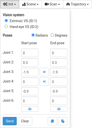 Radio buttons at the top serve for the selection of the vision system to be initialized.
It is necessary to input the start/end poses for each vision system separately. The robot poses can be input either in degrees or radians. To duplicate the pose values (Start -> End, End -> Start) the arrows in between them can be used. To quickly adjust a value for a joint, use the keyboard arrows (changes are automatically applied to the live preview).
To preview/hide a robot pose, click on the show/hide button (the eye icon). A virtual (transparent) robot will show up in the visualizer displaying the robot in that exact pose.
Note: Last used poses are saved in the browser for each solution and are automatically restored when the solution is deployed. This also applies to poses sent in an initialization request from the robot.
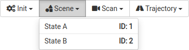 The Change scene state request widget contains a list of scene states defined in the deployed solution. To change the scene state to another one, simply click on its identifier.
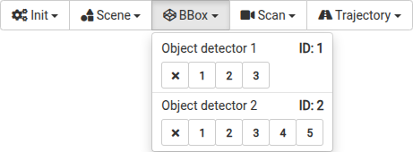 The Change localization bounding box request widget contains a list of vision systems defined in the deployed solution, together with the IDs of the bounding boxes configured within them. To change the localization bounding box for a vision system, simply click on its identifier.
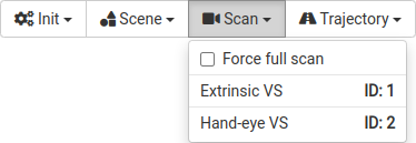 The scan request widget contains a list of vision systems defined in the deployed solution. To trigger a scan for a specific vision system, simply click on its identifier.
The widget additionally allows:
turning on/off the forcing of a full scan (a full scan will be executed even if a fast scan was to be executed originally)
running localization on the last scan (the action request Localize on the last scan)
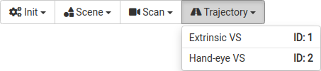 The trajectory request widget contains a list of vision systems defined in the deployed solution. To get a trajectory for a specific vision system, simply click on its identifier.
4 Deployment console
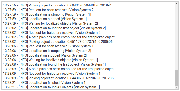
TIMESTAMP - time of the event occurrence
LOG LEVEL - expresses the level of an event - how important a given log message is. BPS defines 4 log levels:
INFO - message that highlights the progress of the application
WARN - message that notifies about potential risk
ERROR - message that informs about an error in the application
FATAL - message that informs about a severe error that causes the application to abort
MESSAGE - text that briefly describes the event
VISION SYSTEM ID - optional, expresses affiliation of the particular event to a specific vision system
All console messages are logged and available for download. To do so, open the BPS menu (top right corner) and select the option Download deployment console logs.
5 Visualizers
View - selection of one of the predefined viewpoints
Camera - option to choose the desired camera mode
Orbit - keeps the base in a horizontal position
Trackball - enables a complete 360-degree rotation
Visibility - option to toggle visibility of the environment objects, sensors, and individual links of the robot and the gripper
Axis - option to visualize the origin of the coordinate system of environment objects, sensors, and individual links of the robot and the gripper
Measure - activates the measurement tool which enables the selection of two points in the scene to get the distance between them
Point Cloud - option to toggle visibility of the point cloud, change the point size and its color
Scan - provides information about the type of the last triggered scan (full/fast), the number of points in the point cloud from the last triggered full scan, and vision system affiliation
Joint States - current joint values of the connected robot
Bounding Boxes - option to render the localization bounding box for a vision system (if enabled)
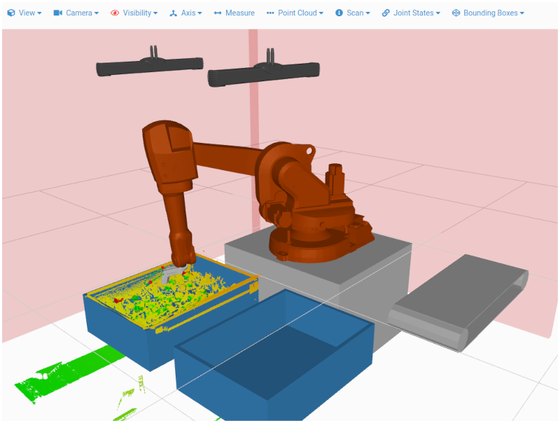
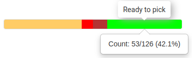
Image 8 - The Object status chart showing the count and percentage value of “Ready to pick” objects
6 Cycle timer
The cycle timer can be used to get some insight into the overall performance of your bin picking application.
The cycle timer displays up to twenty last cycle times in the form of a bar chart. Each vision system (its samples) has its own color representation, samples (action requests) that resulted in an error are rendered in red color. It is possible to toggle the visualization of the data for an individual vision system by clicking the corresponding VS ID button above the chart.
The vertical axis of the chart represents the time axis [seconds]. The height of a sample in the chart represents the duration of the cycle time. Precise value can be seen upon hovering over the specific sample with the mouse cursor - a label window shows up with information about the vision system affiliation and the precise cycle time value. For trajectory requests, in case of an error, the error message is also displayed.
