Preface
This section introduces the 3D Sensors User Manual and explains how to use it effectively.
Use this manual as your primary reference for safe setup, operation, and maintenance of Photoneo 3D sensors. It is intended for engineers, technicians, installers, and integrators working with automation systems.
This manual covers the Alpha 3D Scanner, PhoXi 3D Scanner, and MotionCam-3D (Color) product lines. In this documentation, these models are collectively referred to as a 3D sensor.
Legal Information
Warning Notice System
This user manual contains notices that should be observed to ensure personal safety, as well as prevent damage to equipment. The notices referring to personal safety are “Warning” and “Caution”, while notices referring only to equipment are “Important” and “Note”. The notices are graded according to the degree of danger.
Warning
Indicates that death or severe personal injury may result if proper precautions are not taken.
Caution
Indicates that a minor personal injury can result if proper precautions are not taken.
Important
Indicates that equipment damage can result if proper precautions are not taken.
Note
Indicates that an unintended result or situation can occur if the relevant information is not taken into account.
If more than one degree of danger is present, the warning notice representing the highest degree of danger is used. A notice warning of injury to persons may also include a warning relating to equipment damage.
Qualified Personnel
The device described in this documentation may be operated only by qualified personnel. Qualified personnel means those who, based on their training and experience, are capable of identifying risks and avoiding potential hazards when working with this device.
Installation, commissioning, use, decommissioning, and disposal of this device should be done following relevant documentation, in particular, its warning notices, and safety instructions.
Photoneo 3D Sensors are either Laser Class 3R or Laser Class 2 devices. More information is available in the Projection Unit Properties and Compliance with Standards sections.
Proper Use of Photoneo Products
Please note the following:
Warning
Photoneo products may only be used following relevant technical documentation. If products and components from other manufacturers are used, these must be recommended or approved by Photoneo. Proper transport, storage, installation, assembly, commissioning, operation, and maintenance are required to ensure that the products operate safely and without any problems. The permissible ambient conditions for storage or operation of the device must be complied with. All information provided in the relevant documentation must be observed.
Trademarks
Copyright © 2025 by Zebra Technologies Slovakia s.r.o., Bratislava, Slovakia
Photoneo™, PhoXi™ Control, PhoXi™ 3D Scanner, MotionCam-3D are registered trademarks of Zebra Technologies Slovakia s.r.o.
Products Overview
Photoneo provides two main families of 3D area scanning devices:
MotionCam-3D (Color) is a high-accuracy and high-resolution snapshot 3D area scanning device for large work areas that can be in arbitrary motion. The product is based on a patented CMOS sensor and Parallel Structured Light technology developed by Photoneo. It provides the scanning quality of sequential structured light devices with the ability to scan dynamic scenes.
PhoXi 3D Scanner and Alpha 3D Scanner use a sequential structured light projection to reconstruct the 3D surface geometry of a static scene or object at very high resolution and quality.
All Photoneo 3D Sensors provide onboard calculations of the data which are provided to the user in multiple data formats: depth map, point cloud, normals, and confidence. Data is transferred to the computer running the driver software (see PhoXi Control manual) via a 1Gbps Ethernet connection.
Product Identification
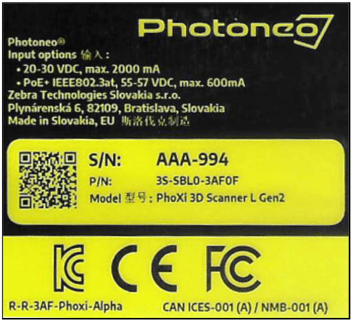
The device description and the manufacturer can be located on the back panel of the device.
Label with manufacturer address, product name, and model, CE, FCC, WEEE, and RoHS marks, country of origin, and input options. Scanning the QR redirects the user to the website of the specific model.
Laser Device
Warning
This device is a laser product. Do not deliberately look into the laser beam. This may cause injury to the retina. The use of protective eyewear is normally not necessary. The laser class label is present on the back of the device.
The laser projector aperture is located on the right side of the front panel of the device (Figure 1). The aperture is marked with a warning label. Do not look directly into the laser projector while the device is in use. Laser Class and Laser parameters used in our devices are discussed in the chapter Projection Unit Properties.
To avoid unauthorized contact with the scanner or unintentional viewing of the laser beam, it is recommended to locate the device in a restricted area and take measures to restrict laser light exposure to the surroundings. Although diffuse reflections are not harmful, users should remove mirrors, polished objects, and similar items from the vicinity of the scanner to avoid specular reflections.
All components of the device, including those sourced from 3rd party suppliers, conform fully with all applicable European directives and regulations.
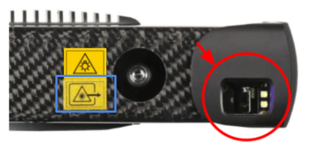
Figure 1: Photoneo scanning device laser aperture location
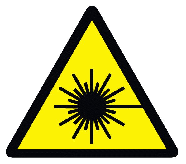
Laser radiation hazard warning symbol.

Laser aperture label. Designates the place from which laser radiation is emitted.
The device uses the following labels and warning systems. Apart from the laser aperture label, all are located on the back panel of the device.
Laser Class 3R devices

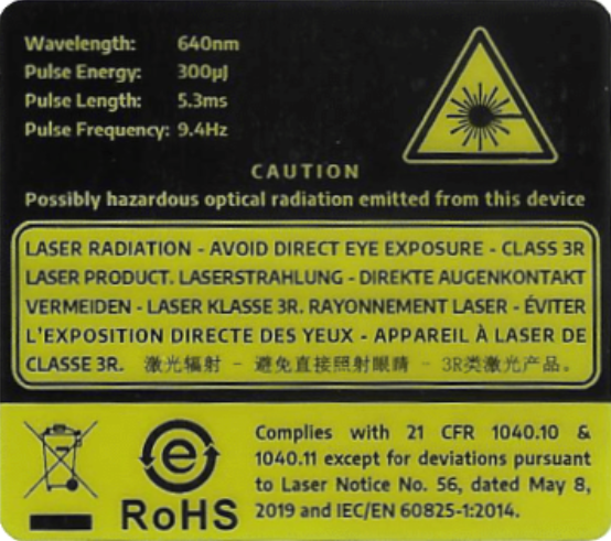
Laser radiation warning with laser class label. The serial number of the device can be found above the warning labels. Label specifying parameters such as wavelength, pulse energy, and pulse length of the laser. (left - blue; right - red)
Laser Class 2 devices
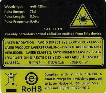
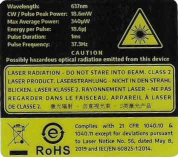
Laser radiation warning with laser class label. The serial number of the device can be found above the warning labels. Label specifying parameters such as wavelength, pulse energy, and pulse length of the laser. (left - blue; right - red)
White LED optical radiation
Warning
Do not stare at the operating lamp. May be harmful to the eyes.
Figure 1: Photoneo scanning device laser aperture location
Visible radiation symbol. IEC 60417-6041:2010-08 for retinal blue light hazard and Retinal thermal hazard.
Objects Suitable for Scanning
Photoneo 3D sensors are measurement devices working on the principle of optical triangulation. Modulated light projected from the projection unit is reflected by the scanned object and captured by a camera unit based on which the distance to the object is computed.
For PhoXi 3D Scanners and Alpha 3D Scanners, which operate on the principle of sequential structured light, the scene must be completely static during the scan.
For MotionCam-3D (Color), which uses the revolutionary and patented principle of Parallel Structured Light™, the scene can be in arbitrary movement or vibration.
As both systems rely on the reflection of projected light, objects most suitable for scanning are (including and not limited to):
rough surface objects, for example, wood, rubber, paper, plaster, etc..
objects with a matte finish, such as sand-blasted aluminum, cast iron, etc..
molded, unpolished plastic materials,
fruits, foods, skin, textiles, plants.
Some objects not suitable for scanning (including and not limited to):
mirrors and polished metals,
most liquids (e.g., water, oil),
translucent and transparent objects (e.g., glass, transparent plastic).
Smoke and particles dispensed in the air still negatively influence the 3D data.
Scope of Delivery
Selected model of Photoneo 3D Sensor
Desktop PoE injector (input: 90 ~ 264 VAC, output: 33.6 W, 56 V, IEEE802.3at) with power cable (1.8 m)
Ethernet cable M12-X male - RJ45 male, 5 m, PUR
Quick Start Guide and Datasheet
Note
Software components are needed for the operation of the scanner. See the section Configuration for more information.
Installation
Guidelines for Installation
A Photoneo 3D Sensor is designed to allow easy installation.
The device can be mounted:
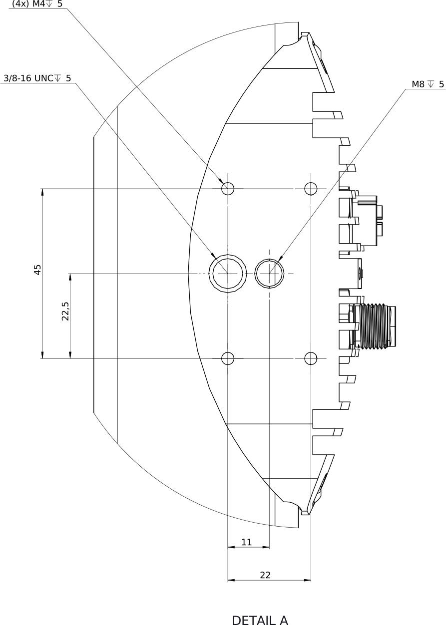
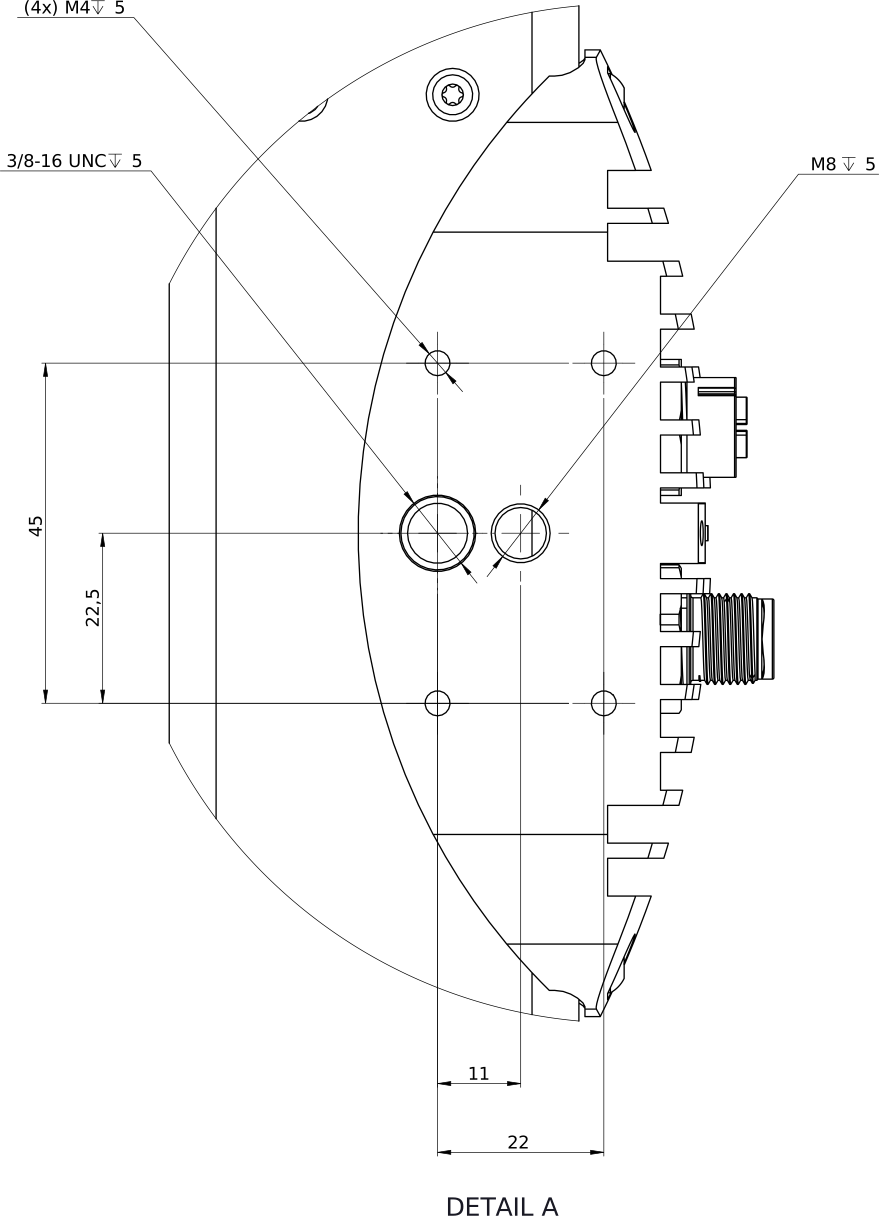
Using a mounting plate of suitable size and 4 M4 screws.
This is the preferred mounting method to ensure rigid mounting of the device to avoid unwanted movement
Using an M8 screw.
On a tripod using a 3/8-16 UNC screw.
To install the device:
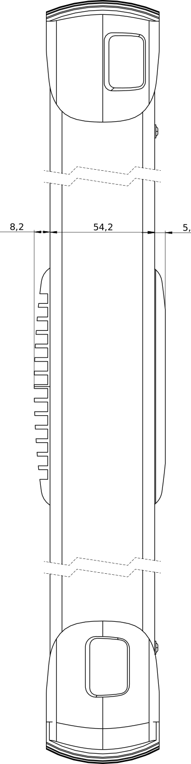
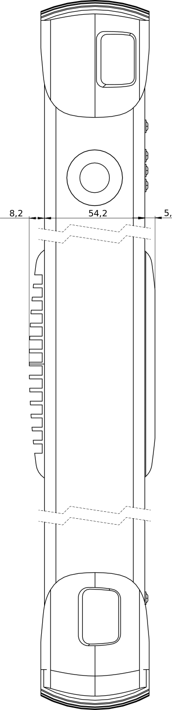
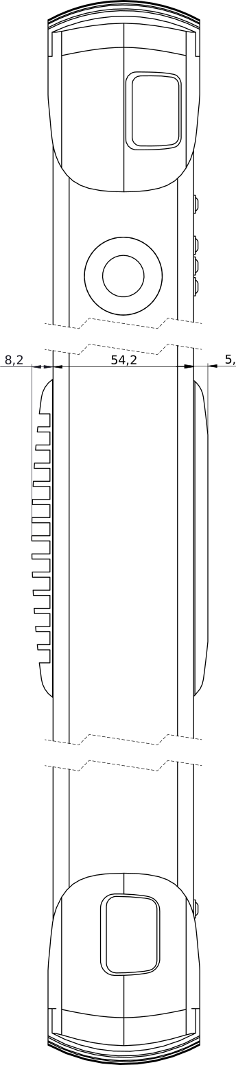
Mount the device using any preferred method. Refer to Dimensions and Illustrations.
When mounting the scanner, ensure that an appropriate scanning distance is set between the scanner and the scanned object and eliminate any potential obstacles.

Figure 2: Mounting plate
Connect the device to the computer or local network and plug it into the power. See the section Powering the device & Data connection for more details.
Download and install the PhoXi Control application from the Photoneo webpage.
Run the PhoXi Control application and try to make your first scan. Please refer to the PhoXi Control user Manual at https://photoneo.com/kb/pxc.
Warning
Hot surface warning. The surface of the processing unit becomes hot to the touch when the device is in use. Mount the device on a metal mounting plate that will act as a thermal bridge to dissipate the heat, or use the carbon body to manipulate the device.
Powering the Device & Data Connection
There are two possibilities for how to power the device:
Using the M12-X Power over Ethernet (PoE) connector (providing both power and data connection)
Using the M12-A 24 V power connector to power the device and the M-12X connector for data transfer

Figure 3: Back panel of the Photoneo scanning device
Powering Through PoE Connector
Connect 1 Gbps capable (not included in the packaging) Ethernet cable to the PoE injector ”DATA” port
Connect the M12-X RJ45 cable to the sensor and to the PoE injector
DATA + POWERportPlug in the power cable of the PoE injector
Note
It is recommended to use a PoE connection to power the device.
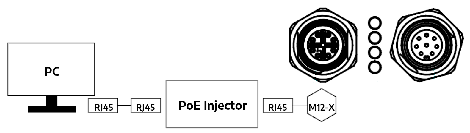
Figure 4: Connection schematics for PoE
Powering by 24 V
Connect the M12-X RJ45 cable to the device and to your computer or switch
Connect the M12-A cable to the device and to the adapter, and plug in the 24 V power adapter
Alternatively, connect the M12-A cable to the device and the open-end wires to the 24 V DIN rail adapter
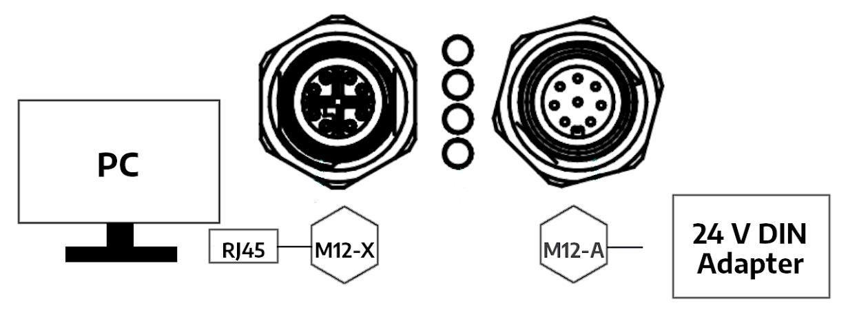
Figure 5: Connection schematics for 24 V power using DIN rail adapter
External Grounding
Safety purposes
The body of the device is constructed from conductive materials: aluminum and carbon. These materials are coated with non-conductive lacquer or anodized aluminum. However, this doesn’t necessarily imply that they serve as effective electrical protective layers. Therefore, relying on them for electrical protection is not assured.
Equipotential bonding is made to protect operators against electric shock. It does not allow two different device’s chassis to have different voltages on them. Connecting these chassis with a conductive wire will bring those chassis to the same voltage potential and protect the operator against electric shock (and protect against ESD as well). Voltages of both chassis will be equal and the operator won’t get hurt by touching both of those devices at the same time.
The point of equipotential bonding is the ground terminal of the building. This is because the Electrical network is (in TT, TN, TNC, and TNC-S cases) tied to the ground. If a dangerous voltage appears on the device chassis, the error current will flow through the ground fault circuit interrupter (GFCI) and switch off the voltage.
EMI reduction
Even though grounding and bonding our sensor is not primarily made for EMI (Electromagnetic interference) reduction purposes, in certain cases, it can improve the EMI behavior of the device. The idea is that the conductive chassis will form a Faraday cage, which will lead the induced current by a path of the smallest impedance to the ground (it is assumed that the intrusive device is connected with the ground directly or by chassis capacity).
To achieve the smallest impedance, we should follow these rules.
The grounding wire must be as straight as possible.
The grounding wire should not be tangled. If the scanner should be moving during the operation, make a half loop only to relax cable bending stress.
Try to use a star topology by connecting the grounding wire of our device directly to the grounding point. Avoid connecting multiple sensors in series.
Avoid ground loops (chassis ground connected in more than one point, for example, the cable shielding and the chassis ground) as they can form a loop antenna and pick up unwanted noise more effectively. If so, the chassis ground should be disconnected at one point to break the loop.
Avoid long or tangled grounding wires. They have higher inductance(and therefore impedance) and are not able to ground high frequencies properly. They can even worsen the EMI.
Required tools:
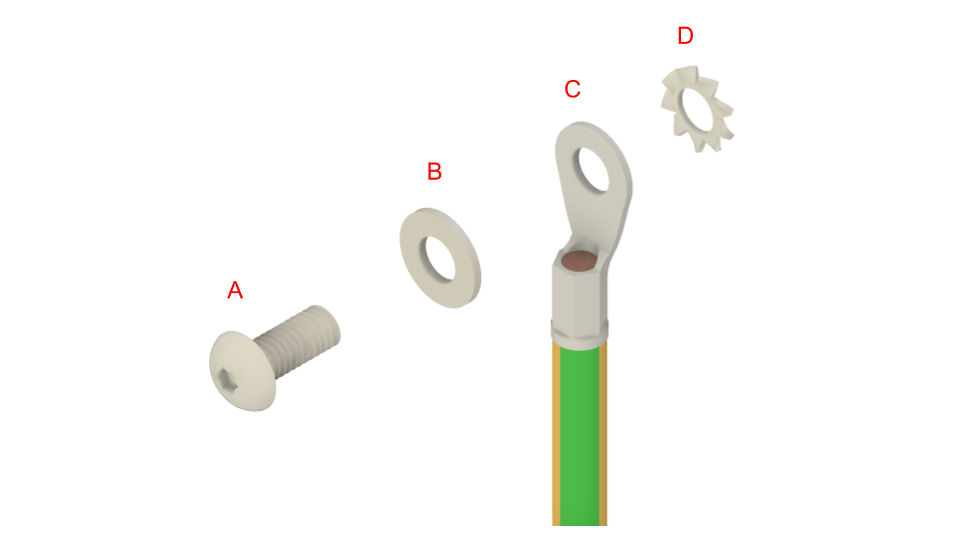
1x Screw M4X10mm (A) - The screw must be long enough to hold washers and lug, but not too long since the hole is blind and has limited depth.
1x Flat washer (4mm hole) (B) - it will make a hard support for a soft cable lug. It will improve the contact quality.
1x Cable lug (4mm hole) © - 2.5-6mm cable (according to the cable used). Lug will manage a good contact between our device and the cable. Lug cable size must be chosen properly, otherwise, the cable won’t be holding well, and the contact will be poor.
1x Fan washer (4mm hole) (D) - this one will bite through aluminum anodization and make good conductive contact.
A screwdriver that will fit the used screw-head.
Lug/cable crimping tool.
AWG11 Copper-stranded wire of the required size (the shorter the better). Use yellow/green stripe-colored wire, as this is the color of a protective conductor according to the IEC 60446 standard.
Instructions:
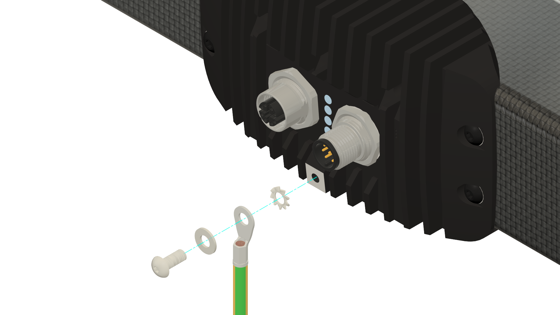
Crimp the lug on the cable, and prepare the screw and washers according to the picture. The fan washer will be in between the scanner and the lug. Its purpose is to bite through the anodized layer and make good contact.
Here is the place where the Grounding terminal is located. Older devices do have this terminal covered with an anodized layer (therefore it is black, not silver).

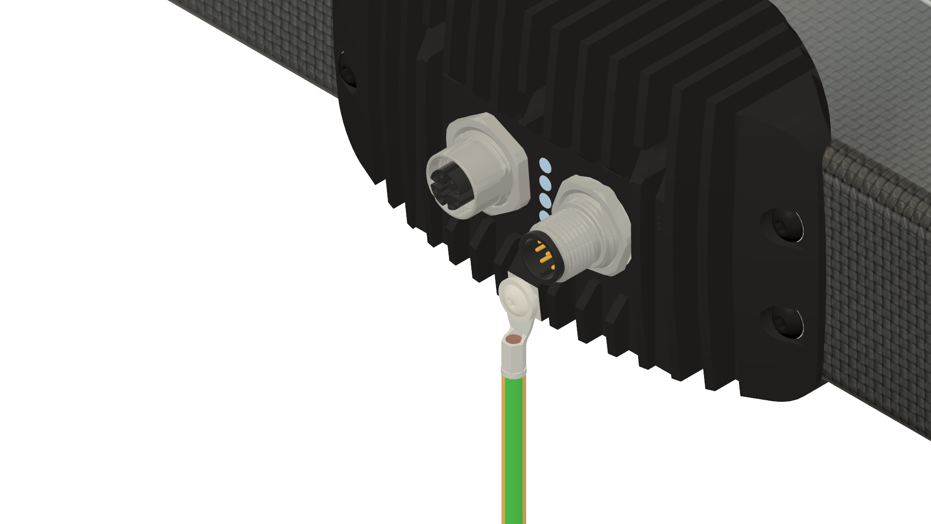
Tight the screw at the recommended 1.3 Nm moment. The cable lug should not be able to rotate. Do not over-tighten the bolt, or the thread in the aluminum body might get damaged.
Connect the device to the grounding terminal in the building. Protective ground should be marked with the following symbol.

Protective ground symbol
Status LEDs
# |
LED Name |
Colors |
Color |
Description |
|---|---|---|---|---|
1 |
POWER |
|
Green |
Power ON and OK |
Red |
Power ON, power on the processing unit not OK |
|||
Off |
No power |
|||
2 |
STATUS |
|
Green |
Firmware ready |
Orange |
Device occupied |
|||
Red |
HW fault |
|||
3 |
ETH1 |
|
Flashing green |
Activity on the link |
Green |
No activity on the link |
|||
Off |
Link is down |
|||
4 |
ETH2 |
|
Green |
Gigabit Ethernet connected |
Off |
No gigabit Ethernet |



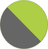

Figure 6: Status LEDs of a device working correctly
Supported Network Topologies
The following network topologies are supported by the Photoneo 3D sensors:
Direct connection to a computer

Figure 7: Direct connection
The sensor connected to a switch

Figure 8.1: Connected to a switch
The following network topology is not supported by the Photoneo scanning device:
The sensor is connected to a router:

Figure 8.2: Connecting the scanner through a router is not supported
Note
Connecting to the scanner via WiFi is not recommended as it is slower and less reliable.
Note
If several 3D sensors are connected to a computer with several Ethernet adapters, using static IP addresses on different subnets is recommended.
Mounting Restrictions
Using external casing for additional Ingress Protection
To protect the device from harsh environmental conditions (high/low temperatures, dust, water jets), it is possible to use an external enclosure.
The effect of the additional (planar) optical element (glass) in front of the device can be split into
a small translation of the point cloud towards the scanning device when compared to the case without the presence of the additional optical element,
a distortion, which is in most practical cases negligible.
Scanner Model |
||||
|---|---|---|---|---|
S |
M |
L |
XL |
|
Translation [mm] |
1.140 |
1.140 |
1.127 |
1.124 |
RMSQ of distortion [mm] |
0.090 |
0.088 |
0.088 |
0.092 |
Max. distortion [mm] |
0.216 |
0.220 |
0.208 |
0.202 |
Max. local relative distortion [promile] |
1.9 |
1.4 |
0.7 |
0.4 |
Max. local rotation [angular minute] |
9.5 |
6.3 |
3.5 |
1.9 |
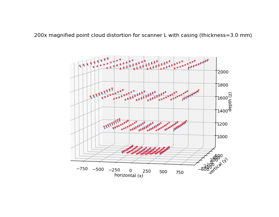
Figure 9: Point cloud distortion for scanner L with casing magnified 200 times (thickness = 3.0mm)
Movement During Scanning
In general, MotionCam-3D (Color) can be mounted on moving constructions or robotic arms, as it can capture dynamic scenes as well as static scenes. The device itself, as well as the scenes, can be in motion or vibrating.
It is possible to mount the PhoXi 3D Scanner on moving constructions or robotic arms, however, it is necessary to stop the movement during the acquisition. Movement of the scanner during the projection of light patterns causes a loss of quality and interferes with depth calculation. Make sure the device and the scanned area are still during the acquisition.
If vibrations are present, use a damping apparatus to isolate the scanner’s mounting from the source of the vibrations. Acceleration and deceleration forces according to the scanner’s environment restrictions should be taken into account when designing the mount for the scanner. The maximum acceleration allowed during operation (not including the scanning process) is up to 20 ms-2.
Strong Electric Field
As a general rule, always isolate low-voltage, logic-type devices such as Photoneo 3D Sensors from devices that are high voltage and generate high electrical noise. Carefully consider the routing of the wiring for the devices in the panel as well. Avoid placing low-voltage signal wires and communication cables in the same tray with AC power wiring and high-energy, rapidly-switched DC wiring.
Clearance for Cooling and Wiring
Photoneo 3D Sensors are designed to be cooled via natural convection cooling. When designing a mount or an enclosure, refer to the CAD models available at https://www.photoneo.com/downloads/device-resources/ to ensure you use the up-to-date device dimensions.
Important
In order to ensure adequate cooling, a clearance of at least 25 mm around the device must be allowed. When planning the placement of the Photoneo 3D Sensor, consider placing heat-generating and electronic-type devices in the cooler areas. By reducing exposure to high-temperature environments, you can extend the operating life of electronic devices considerably.
Important
To ensure optimal performance of Photoneo devices, maintain proper ventilation and unobstructed airflow. This is crucial even within the recommended temperature range (refer to device datasheets for specific temperature limits). Inconsistent or blocked airflow may cause the device to enter a cooling mode in extreme cases, temporarily stopping recordings to prevent overheating.
Note
It is recommended to mount the device on a metal plate that will act as a thermal bridge and dissipate the heat produced by the processing unit away from the scanner.
Turning Off the Device
Before turning off the device, make sure it is not actively scanning - the device is not projecting laser patterns. Turn it off by unplugging it from the power.
Note
It is not recommended to unplug the device from the power while it is actively scanning. This is to prevent possible damage to the projection unit.
Laser Safety Interlock
Note
Not all devices have the Laser Safety Interlock feature. This feature must be enabled per request at Photoneo premises before shipping.
To operate the device, it is necessary to supply a high signal (5 - 24V) on the Pin 8 (OPTO_IN2) on the 24V connector. If no power is present (low signal) on Pin 8 (OPTO_IN2), the projection unit will not emit light.
Please, refer to the Powering the Device & Data Connection subsection for full powering instructions. Laser Safety Interlock can be used in combination with PoE or 24V powering.

24 V connector - view from the mating side
Wire number |
Color |
Function |
|---|---|---|
1 |
White |
DC_IN:+ 24 V |
2 |
Brown |
OPTO_IN2_GND: laser interlock ground |
3 |
Green |
ground |
4 |
Yellow |
– |
5 |
Grey |
– |
6 |
Pink |
– |
7 |
Blue |
– |
8 |
Red |
OPTO_IN2: laser interlock signal 5 - 24 V |
Configuration
Photoneo sensors can be operated via a dedicated application - PhoXi Control or other GigE Vision-compatible 3rd party applications. PhoXi Control application enables users to control Photoneo 3D Sensors manually via a GUI or by a computer program using the provided API or GenICam interface. Alternatively, Photoneo sensors can run in GigE Vision compatible mode in which PhoXi Control cannot be used.
PhoXi Control
The GUI is primarily used to set up the scanning environment, configure advanced scanner parameters, and visualize the output. In addition, the GUI can also be used as a powerful debugging tool for development with the API. Calls to the API trigger the same response in the GUI as user inputs. After triggering the scan by calling the API method, the application will execute the scan, send it as an output of the call, and display it simultaneously in the GUI.
The API serves as a central platform for building custom applications for Photoneo 3D Sensors. In order to facilitate the development process and reduce computing demands, all computations are performed on the device itself.
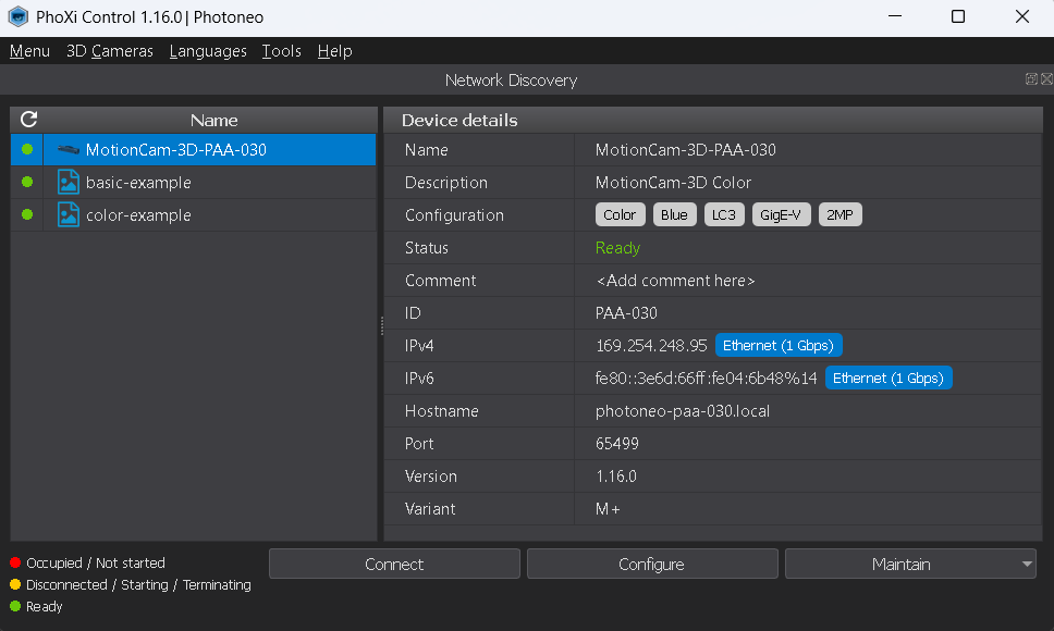
Figure 10: PhoXi Control – Network Discovery
GenICam interface (Discontinued) 
The Generic Interface for Cameras standard is the base for plug-and-play handling of cameras and devices. It was developed by the European Machine Vision Association (EMVA)
GenICam support is provided via the GenTL library that works as a wrapper around the PhoXi Control C++ API. PhoXi Control has to be running to use the GenICam interface.
You can download the latest version of PhoXi Control and the PhoXi Control User Manual from our website at https://www.photoneo.com/downloads/phoxi-control/. User guides for GenICam integrations contain more detailed information and requirements for running the examples.
The complete list of GenICam/GigE Vision settings is documented in the GenICam Settings section at the end of this manual.
GigE Vision 
To enable or disable GigE Vision functionalities, download and install the necessary utilities from the provided corresponding links:
GigE Vision utilities for Windows: www.photoneo.com/dl/gigev-utils-win
GigE Vision utilities for Linux: www.photoneo.com/dl/gigev-utils-lin
Hardware Parameters
Powering the device
The following subsections explain different options for powering a Photoneo 3D Sensor. In case both the PoE and 24 V connector (M12-A) are used to power the device, PoE is prioritized.
Power Over Ethernet Connector
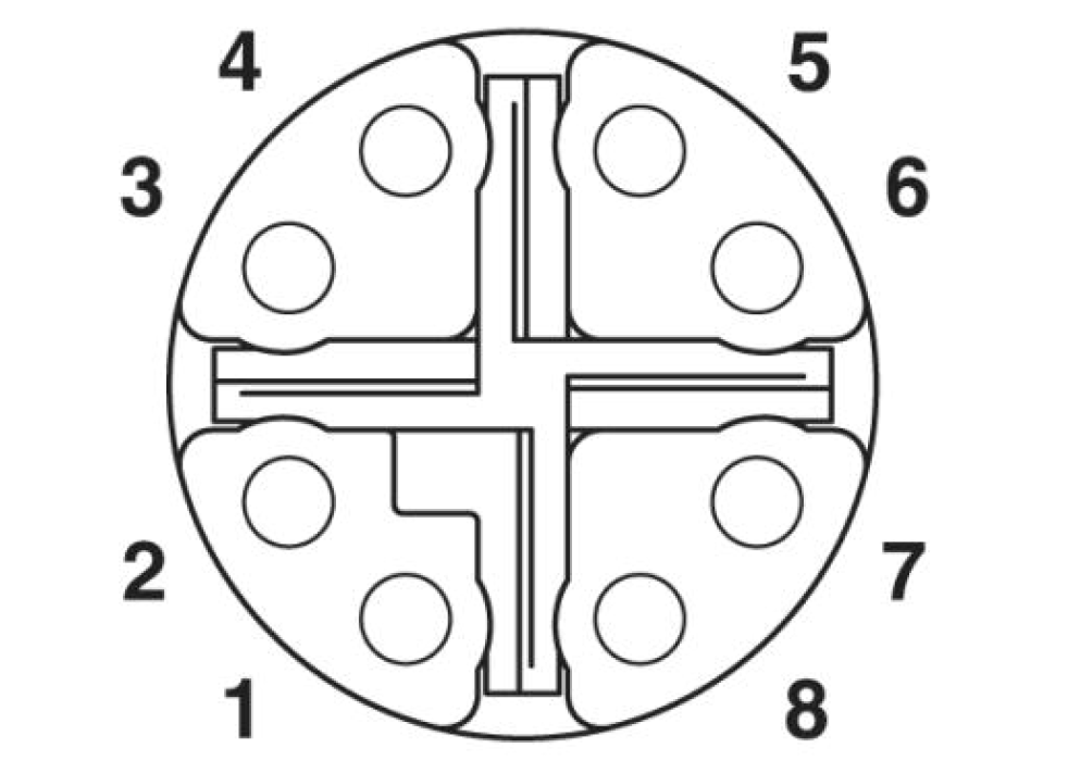
Figure 11: PoE connector pinout, view from the mating side
Connector type: M12 X coded, 1404741

Figure 12: Contact assignments of the M12 and RJ45 plugPowering Requirements
Powering Requirements
PoE Standard |
IEEE802.3at |
Operating voltage Ue DC |
min. 55 V |
Residual ripple maximum (% of Ue) |
0.5 % |
Rated operating current Ie (Imax) |
0.360 A (0.6 A) |
Minimum Power |
33 W |
Shielding |
Fully Shielded RJ45 |
Transfer data rate |
1 Gbit |
Maximum recommended cable length |
20 m (wire cross area 0.14 mm²) |
24 V Power Connector (M12-A)
Figure 13: 24 V Power & GPIO pinout, view from the mating side
Connector type: M12 A coded, M12A-08PMMP-SF8001
Pin |
Pinout |
Function |
|---|---|---|
1 |
DC_IN |
+24 V |
2 |
OPTO_IN2_GND |
*laser interlock ground |
3 |
GND |
ground |
4 |
OPTO_IN1 |
hardware trigger input signal (5 - 24 V) |
5 |
OPTO_IN1_GND |
hardware trigger input ground |
6 |
OPTO_OUT |
hardware trigger output signal (5 - 24 V) |
7 |
OPTO_OUT_GND |
hardware trigger output ground |
8 |
OPTO_IN2 |
*laser interlock signal (5 - 24 V) |
* Laser interlock safety feature must be enabled per request at Photoneo premises before shipping.
Powering Requirements
Operating DC voltage Ue (Umin-Umax) |
24 V (20 - 30 V) |
Residual ripple maximum (% of Ue) |
2 % |
Rated operating current Ie (Imax) |
1 A (2 A) |
Minimum Power |
60 W |
Maximum recommended cable length |
20 m (wire cross area 0.25 mm²) |
Hardware Trigger Characteristics
Hardware trigger provides the user with means of triggering devices by external means - outside of the software environment. More information on the software configuration can be found in the PhoXi Control User Manual. This functionality is mostly used for synchronization purposes:
With external events, such as an object arriving inside the field of view of Photoneo 3D Sensor (i.e. triggered by an optical gate)
With other devices, such as 2D cameras, PLCs, …
With multiple Photoneo 3D Sensors
The hardware trigger is activated by feeding a logical signal to the specified pin of the M12-A connector. The device is also able to signal that it is currently acquiring → this signal can be read from the output pin on the M12-A connector.
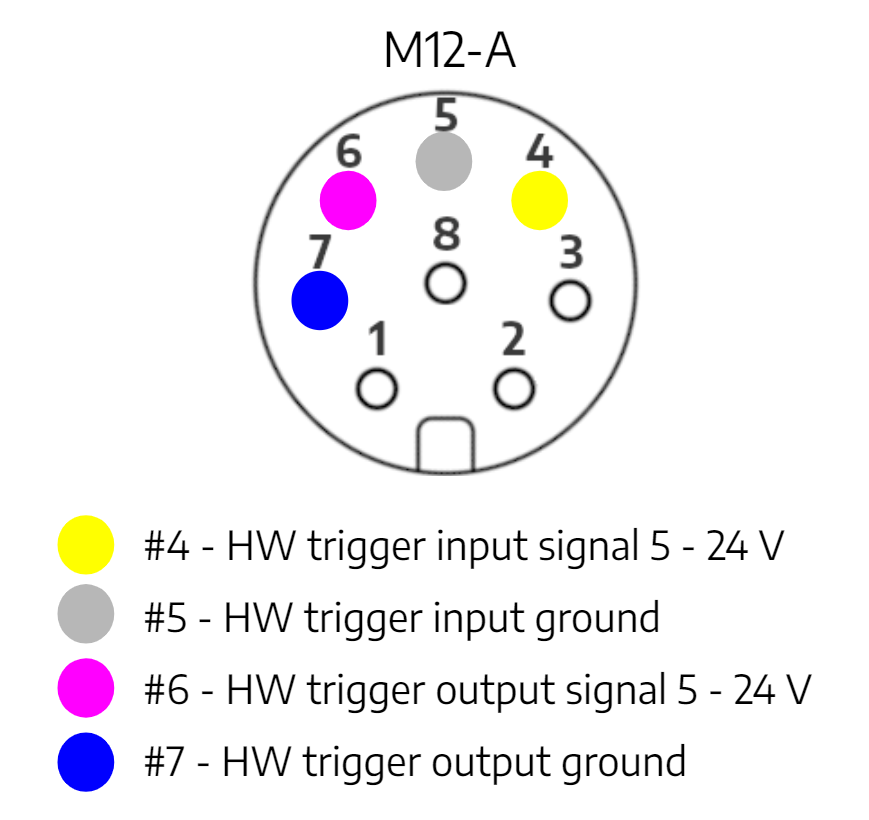
View of the port on the Photoneo 3D Sensor (similar to the previous figure)
The allowed input signal voltage range is 5 - 24 V, depending on the user’s requirements. The output signal needs to be read through a pull-up resistor.
To correctly connect/wire the devices together, please adhere to the following schematics for trigger input and trigger output.
Trigger Input
Circuit Characteristics
Both wiring schematics below are valid. It is recommended to
Use \(R = 0\ \mathrm{\Omega}\ \)if your \(VCC = 5 - 12\ V\)
Use \(R = 4k7\ \mathrm{\Omega}\ \)if your \(VCC = 24\ V\)
The trigger input can be done as a common cathode or common anode. Refer to the diagrams below.
Common Cathode

Common Anode

Figure 14: Trigger input wiring options
Input Signal Characteristics
The trigger input signal causes the device to start the acquisition. In the case of MotionCam-3D the trigger input signal is a transition between logic zero and logic one. Therefore the signal can be:
Falling edge → change from logic 1 to logic 0
Rising edge → change from logic 0 to logic 1
The choice of the signal depends on the specifics of the setup. For example, the setup for a falling edge can be:
The input pin is kept at 24 V and it’s lowered to 0 V to produce the falling edge
The input pin is kept at 0 V and it’s elevated to 24 V for a short period of time. Letting it fall back down produces a falling edge that triggers the device
Whether the device is triggered by a falling edge, rising edge, or both is controlled by a parameter called Hardware Trigger Signal.
Trigger Output
Circuit Characteristics
The trigger output is read through the VCC pull-up. Please refer to the diagram below. It is recommended to
Use a \(R = 10k\ \mathrm{\Omega}\) resistor to read the signal (for example using a PLC)
Use a \(R = 1k6\ \mathrm{\Omega}\) resistor when the MotionCam-3D is daisy-chained with another MotionCam-3D and your \(VCC = 5 - 12\ V\)
Use \(R = 4k7\ \mathrm{\Omega}\) resistor when the MotionCam-3D is daisy-chained with another MotionCam-3D and your \(VCC = 24\ V\)
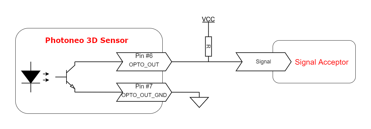
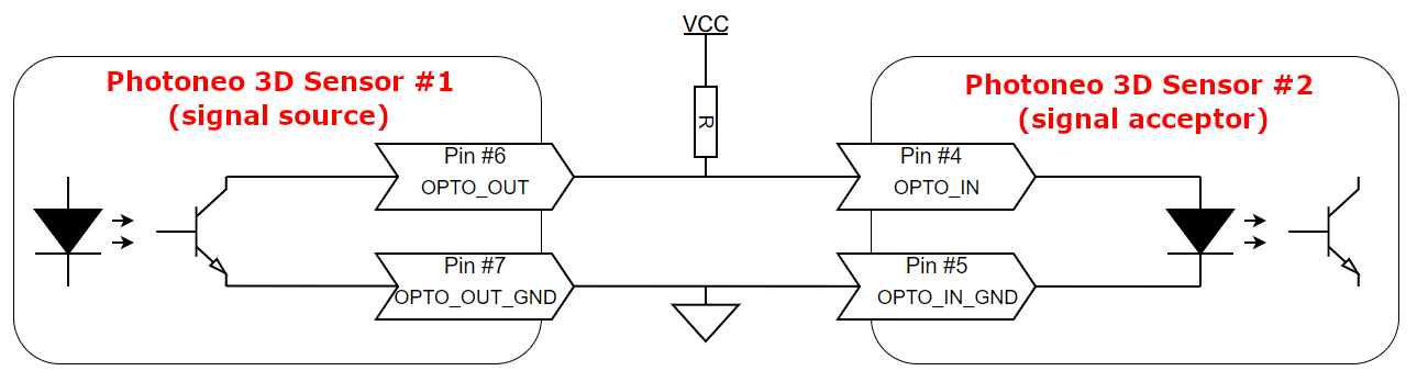
Figure 15: Recommended wiring for trigger output
Output Signal Characteristics
The trigger output signal is used to mark the time during which the device is in acquisition. Once the acquisition starts, the signal changes from logic 0 to logic 1. After it finishes, it changes from logic 1 to logic 0.
The acquisition is defined as follows:
In camera mode → the time during which the laser sweeps the scene and the 3D data are gathered.
In scanner mode → the time it takes to project all necessary patterns as well as LED texture.
Simplified wiring schemes

SEXT A |
Single device triggered by HW trigger - Common Cathode |
SEXT B |
Single device triggered by HW trigger - Common Anode |
MEXT |
Multiple devices triggered by HW trigger independently from each other |
INTSEQ |
Two or more devices triggered sequentially in a daisy chain - triggered by the Sensor #1 |
EXTSEQ |
Two or more devices triggered sequentially in a daisy chain - Sensor #1 triggered externally |
EXTDCL |
Two or more devices triggered sequentially in a loop - daisy chain in a loop |
OUT |
Photoneo 3D Sensor outputs a signal to another device (Signal Acceptor) |
*Resistors Ri and Ro are dependent on the voltage of the power source and type of the connected devices - refer to the sections Trigger Input and Trigger Output.
Ground pins OPTO_IN_GND and OPTO_OUT_GND can be connected to the same ground (of the voltage source) - in this case, OPTO_GROUND (separate from the ground of the sensor itself).
Projection Unit Properties
Projection unit type |
Laser Class 2 - Red |
Laser Class 2 - Blue |
Laser Class 3R - Red |
Laser Class 3R - Blue |
||
|---|---|---|---|---|---|---|
Light source |
Visible red light (laser) |
Visible blue light (laser) |
Visible red light (laser) |
Visible blue light (laser) |
||
Laser class |
2 |
2 |
3R |
3R |
||
Wavelength |
637 nm |
440-455 nm |
640 nm |
440-455 nm |
||
Pulse energy |
18.6 μJ |
72 μJ |
300 μJ* |
89 μJ* |
470 μJ |
|
Pulse length |
1 ms |
5.0 ms |
5.3 ms |
5.3 ms |
||
Projection width horizontal |
47.5° ± 1° |
47.5° ± 1° |
47.5° ± 1° |
47.5° ± 1° |
||
Projection width vertical |
36.0°± 2° |
45° ± 1° |
36.0°± 2° |
45° ± 1° |
||
*Depends on the specific model. Contact our Help Center for more information.
Make sure to check the values found on the back side of your Photoneo 3D Sensor for the exact parameters.
Note
Contact our Help Center or your Photoneo Sales Representative to get more information about the projection unit types that are available for the requested model.
Environmental Conditions
Transport
Ambient temperature |
From -20 °C to 50 °C (max gradient 10 °C/hour) |
Humidity |
From 0 % to 95 % non-condensing |
Atmospheric pressure |
From 1080 hPa to 660 hPa (corresponding to an altitude of -1000 m to 3500 m) |
Caution
Please ensure that the device is always transported in its original casing or that it is properly cushioned for transport.
Operation
Operating temperature for optimal scanning performance |
From 22 °C to 25 °C |
Overall operating temperature |
From 0 °C to 40 °C |
Humidity |
From 0 % to 95 % non-condensing |
Atmospheric pressure |
From 1080 hPa to 660 hPa (corresponding to an altitude of -550 m to 3500 m) |
Maximum acceleration (idle) |
20 ms-2 |
Note
For the correct performance of the device, make sure it has reached its operating temperature. The operating temperature is reached approximately after 45 minutes of the device being powered up or after 10 minutes of continuous scanning in the free run mode, followed by 2 - 5 minutes of cool down to stabilize the temperature.
Degree of Ingress Protection
Photoneo 3D Sensors have the following mechanical protection according to standard EN 60529:
IP65 Mechanical Protection
Completely protected against the ingress of dust (dust-tight).
Protected against low-pressure jets of water from any direction.
Cleaning Instructions
The optical scanning device produced by Photoneo is technically advanced yet a low-maintenance device. To preserve the performance and quality of the scanning, please check and maintain its outer optical parts regularly.
The glasses covering the camera unit and the projection should not be touched by bare hands to avoid staining the glass. This could interfere with light passing through them. If the glass was touched or lightly stained by any other mechanism, wipe the glass with lint-free wipes intended for optical components.
In cases where the device is used in an environment with lots of dust, especially when the dust contains sharp or hard particles that could potentially damage the glass, clean the glasses with a specialized cleaning solution for optical components, e.g.: First Contact™ Cleaning Solution.
To clean the glasses:
Coat the glass with the solution using the applicator. Make sure not to spread it to the edges. The solution immediately dries and creates a film over the glass.
Remove the film from the glass using peel tabs with wooden or plastic tips.
The film removes any dirt or particles from the glass.
|
|
|


Figure 16: Cleaning process of the glass over the camera unit
Scanning Parameters
Datasheet Parameter Definitions
The datasheet defines several performance properties of a Photoneo 3D Sensor. A population of production devices is characterized by the typical and maximum observed values, given a properly maintained device. The typical value represents the performance of the average device, while the maximum value is the upper limit of the population. Some of the performance properties were determined theoretically from a model.
The table values represented in the datasheet are the maximum values. The graphs show both maximum and typical values.
Standard Conditions
The Standard Conditions refer to a stable environment for measurements, characterized by homogenous ambient light, excluding strong or flashing light sources other than the verified device, a stable humidity and stable room temperature (ISO 554), and the absence of shocks or shaking.
3D Sensing Technology
Photoneo 3D Sensor either uses sequential structured light technology or Parallel Structured Light Technology. More information can be found in the section Objects Suitable for Scanning of the Photoneo 3D Sensors - User Manual.
Output Data
Depending on the device used for scanning, the output data structure can differ.
3D points (x y z)
Floating numbers depicting the position of a 3D point in a given coordinate frame. The default coordinate frame has its origin in the 2D camera with the Z-axis towards the scene, the X-axis continuing to the right of the device, and the Y-axis facing downward.
Normals (x y z)
The normal vector for each 3D point can also be calculated. The normal vector is perpendicular to the area surrounding the point.
Depth Map (z)
The “depth” of a point is the absolute 3D distance from the image sensor to the measured point (the ray of light that hits the surface of the object). The DepthMap is, therefore, always in the camera coordinate system and corresponds to the Z coordinate value in the point cloud.
Color Image (RGB)
A 2D RGB texture is available on the MotionCam-3D Color and PhoXi 3D Scanner Gen3 at different resolutions.
Texture (grayscale/RGB)
A 2D texture (LED, Computed, Laser, Focus, Color).
Confidence (float)
For each measured 3D point, the “confidence” value expresses certainty about the accuracy of the point measurements. For example, a confidence value of 0.12 means that the estimated error for a point measurement is 0.12 mm. This value is based on a heuristic method that considers the light conditions for each pixel.
Scanning Distance
Scanning distance is the distance between the sensor and the verification object. It can be expressed in millimeters or simplified into terms such as near, sweet, or far to describe the minimal, ideal or maximal distance of the scanned object from the device.
Point-to-Point Distance
The Point-to-Point Distance is the average lateral distance between the closest neighboring points in the point cloud at the specified distance from the sensor. It can also be interpreted as the average diameter of a patch associated with a single 3D point observed at a specific distance from the sensor
Figures 17 and 18 show the point size as a function of the scanning distance. The point size linearly increases with the distance. Therefore, it is possible to calculate the approximate point size using the Optimal scanning distance (sweet spot) and the point-to-point distance (at the sweet spot) values, which can be found in the datasheet. If \(P_{s}\) is the point size at the optimal scanning distance \(D_{o}\), then we can calculate the approximate point size \(P\) at the desired distance \(D_{d}\) as follows:
\(P\ = \ (\frac{P_{s}}{D_{o}})\ \times \ D_{d}{}_{}{}_{}\)
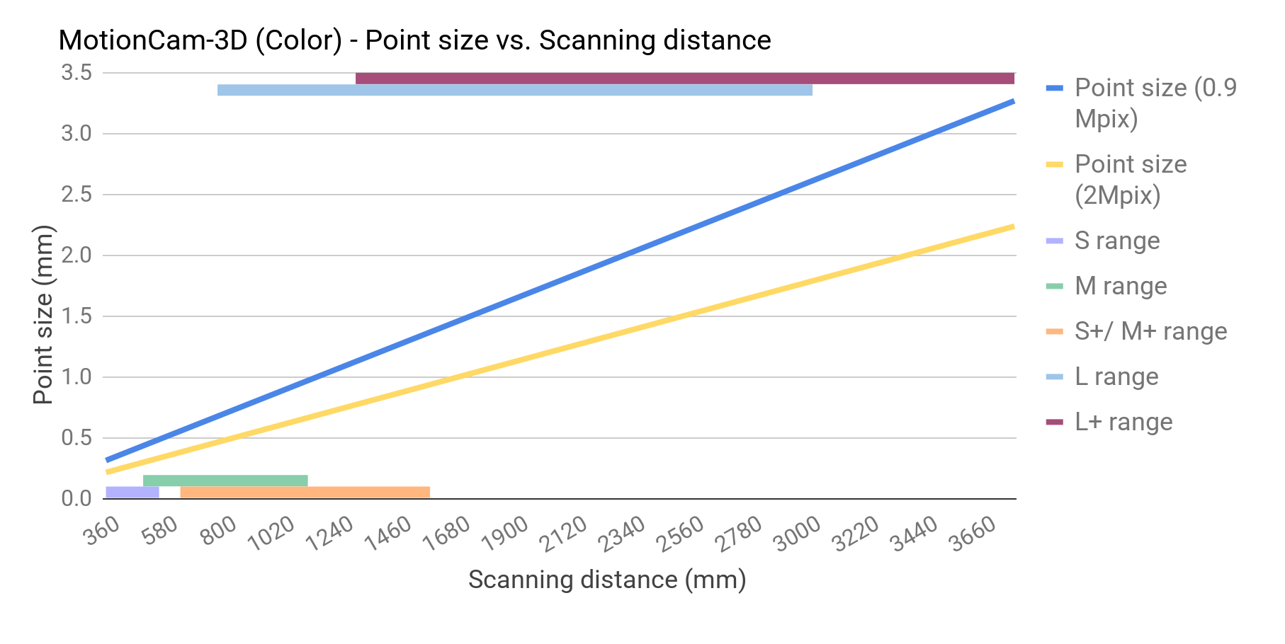
Figure 17: Relationship between scanning distance and point size for the MotionCam-3D (Color) devices
Figure 18a: Relationship between scanning distance and point size for the PhoXi 3D Scanner Gen3 devices
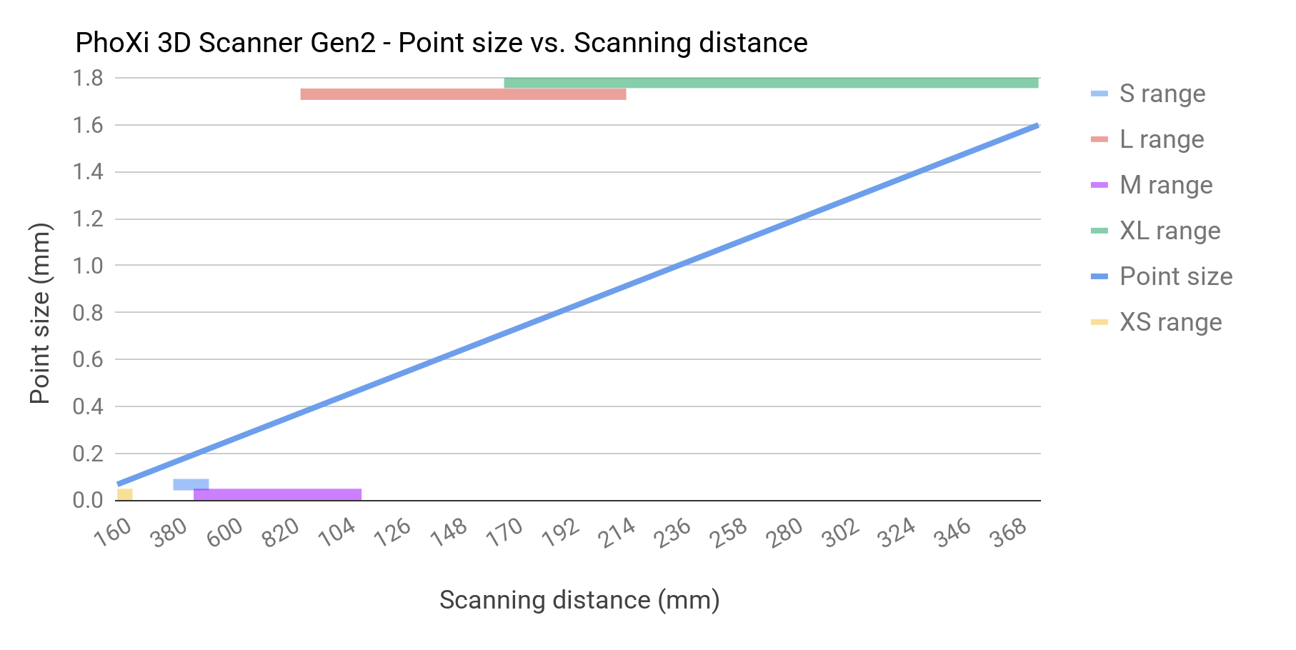
Figure 18b: Relationship between scanning distance and point size for the PhoXi 3D Scanner Gen3 devices

Figure 19: Relationship between scanning distance and point size for the Alpha 3D Scanner devices
Scanning Time
The total Scanning Time is the sum of the time required for acquisition, computation, and transfer.
Depth Map Resolution
The Depth Map Resolution defines the number of pixels of the primary 2D camera used for 3D sensing.
Color Image Resolution
The Color Image Resolution refers to the number of pixels of the secondary RGB camera. The resolution of the RGB camera can be set to one of the predefined values. Note that the Color Image Resolution is independent of the Depth Map Resolution.
Frames Per Second
The Frames Per Second (FPS) expresses the maximum achievable frame rate, i.e., the number of 3D scans per second. The FPS value can be affected by the selected profile or parameters.
Dimensions
The Dimensions are expressed in 3 values that represent the length, height, and depth of the device in millimeters, respectively.
Baseline
The Baseline is the distance between the primary 2D camera and the projection unit.
Weight
Weight of the device (without accessories).
Temperature Working Range
The Temperature Working Range refers to the operational range of temperatures of the Photoneo 3D Sensors. To achieve the optimum scanning performance, the sensor needs to be thermalized within the optimal temperature range (standard atmospheric conditions defined by ISO 554).
Projection Unit Laser Color
The Projection Unit Laser Color describes the color of the laser used in the sensor’s projection unit. The type of the projection unit can have an effect on the scanning performance on specific scenes and objects.
Power
The device can be powered using a Power over Ethernet injector or a 24V adapter. Further information can be found in section Powering the Device & Data Connection.
Processing Unit
The processing unit for Photoneo 3D Sensors is the NVIDIA Jetson TX2. This unit performs all 3D data computations directly on the device, which helps to reduce external computing demands
IP Rating
Indicates the level of protection against solid particles and liquids, as defined by IEC 60529. The first digit rates dust protection, the second rates water resistance; higher numbers mean greater protection.
For more information, visit : https://www.iec.ch/ip-ratings
Data Connection
It is recommended that the device be connected to a 1 Gbit network to ensure sufficient data flow.
Tools for Infield Maintenance
Photoneo 3D Sensors offer a variety of tools for infield maintenance.
Maintenance Tool
Supported on MotionCam-3D, MotionCam-3D Color, PhoXi 3D Scanner, Alpha 3D Scanner devices
Required pattern - Yes
Marker pattern
Can be purchased from Photoneo
Printing is possible but not recommended as even small scaling printing inaccuracy can lead to incorrect calibration
Command line application executable via PhoXi Control GUI and API
Marker Dots Correction
Supported on MotionCam-3D, MotionCam-3D Color, PhoXi 3D Scanner, Alpha 3D Scanner devices (shipped after 05-26-2025)
Required pattern - Yes
4 or more Marker dots required (must be purchased from Photoneo)
GUI, API
GigE*
Autonomous Maintenance
Supported on MotionCam-3D Color (shipped after 05-26-2025)
Required pattern - No
GUI, API
GigE*
*Limited functionality - feature can be activated without status reporting
Using one or combination of the tools is recommended:
During system setup, before starting operations
If the device experienced extensive vibration or physical shock (transport, robot collision)
After major environmental changes, like a relocation or temperature/humidity fluctuation
As a part of a precision-focused workflow, where you might want to run a quick check regularly (recommended once or twice a year, or during general system maintenance sessions)
Maintenance Tool
Maintenance Tool is a Photoneo software used to validate 3D Sensors by acquiring a marker pattern, verifying calibration, and adjusting it if needed. It requires a marker pattern printed on a high-quality surface and the device to be running for at least 45 minutes. Detailed manual can be found in Tools for Infield Maintenance section in PhoXi Control User Manual.
Marker Dots Correction
Marker Dot Correction is a feature that helps maintain a 3D Sensor’s point cloud at a fixed position relative to permanently installed marker dots. It requires a Photoneo 3D Sensor (shipped after May 26, 2025) with Firmware 1.15 or higher, and specific Photoneo marker dots (65x65mm or 140x140mm). Detailed manual can be found in Tools for Infield Maintenance section in PhoXi Control User Manual.
Autonomous Maintenance
Autonomous Maintenance is a feature for MotionCam-3D Color devices (shipped after May 26, 2025) with firmware 1.15 or higher and for PhoXi 3D Scanner Gen3, designed to maintain long-term measurement accuracy without manual intervention or external markers. It requires a static scene during calibration checks and the device to be running for at least 45 minutes. Detailed manual can be found in Tools for Infield Maintenance section in PhoXi Control User Manual.
For more information on how to use and activate each of the Tools for Infield Maintenance, please check the same name section in the in PhoXi Control User Manual.
Compliance with Standards
Photoneo 3D Sensors conform to the following standards and test specifications. Please note that the certification status may change without notification. Consult your local Photoneo representative if you need additional information related to the latest listing of exact approvals.
CE
Photoneo 3D Sensors satisfy requirements and safety-related objectives according to the EC directives listed below. This CE mark is supported by tests conducted by the manufacturer.
Laser Classification
The Laser class of the devices is determined according to EN 60825-1:2014 Equipment Classification and Requirements standard. The laser class was tested by an independent certification body.
Photoneo 3D Sensors are Laser Class 3R or Laser Class 2 devices. All devices are labeled according to their respective class following rules given by the harmonized standard.
Details about the laser device used can be found in the section Projection Unit.
If necessary, please contact Photoneo for a written Declaration of Laser Class for your specific device.
Dimensions and Illustrations
Bottom View: Mounting Plate
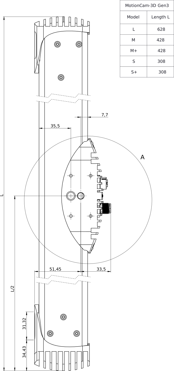


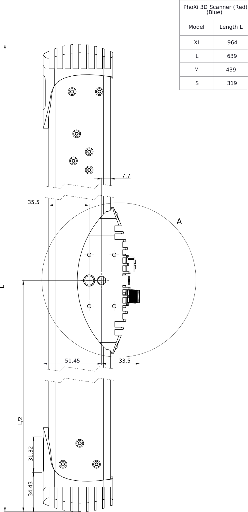
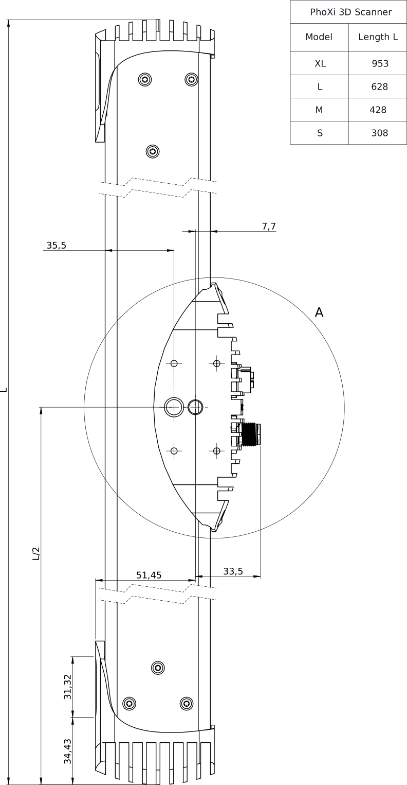
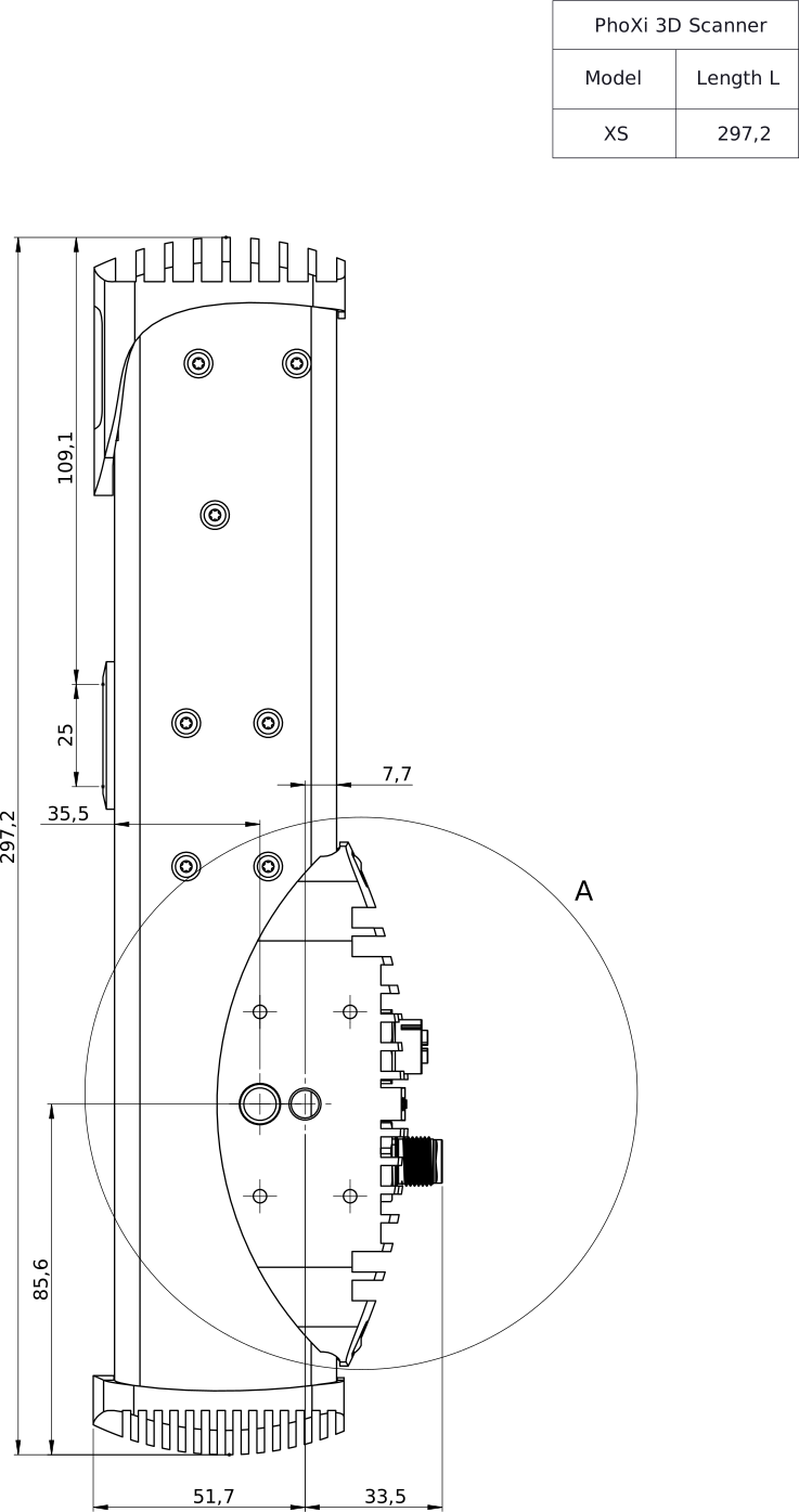
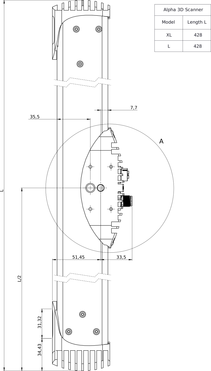
Bottom View: Detail



Front View: Projection Unit and Camera Unit



Warranty
A standard 1-year warranty applies. Full warranty conditions are stated in the General Terms and Conditions on the Photoneo website: https://www.photoneo.com/kb/tc
GenICam Settings
The complete list of GenICam / GigE Vision settings, generated from the Photoneo settings descriptor.