How to begin
You are in the right place to begin with your Photoneo 3D Sensor.
If you have just unpacked your device, this guide walks you through the first essential steps:
verify what is included in the package,
connect and power the sensor correctly,
follow key safety recommendations,
and get ready for first operation.
Use this page as your starting point before moving to the full user manual and advanced documentation.
Scope of delivery
Photoneo 3D Sensor (MotionCam-3D, MotionCam-3D Color, PhoXi 3D Scanner, Alpha 3D Scanner)
Box and cushion (it is recommended to keep the box and cushion for further transport of the device)
Quick Start Guide
According to the specific part numbers in the order:
Desktop PoE injector (input: 90 ~ 264 VAC, output: 33.6 W, 56 V, IEEE802.3at), power cable 1.8 m)
Ethernet cable M12-X male - RJ45 male, 5 m, PUR
Operation of the Device
Use the PhoXi Control application on your computer, or a GigE Vision-compatible 3rd party application to operate the Photoneo 3D Sensor. PhoXi Control allows users to control the device either manually through a graphical user interface or programmatically through the provided API. Download PhoXi Control and GigE Vision examples at https://photoneo.com/downloads/phoxi-control/.
Safety
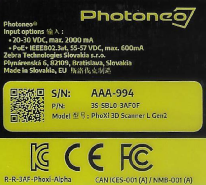
Photoneo scanning device is a Laser Class 3R device or a Laser Class 2 device. Class 3R lasers are considered safe when handled carefully. Class 2 lasers are considered safe for normal operation. See the label on the back of the device to determine its laser class.
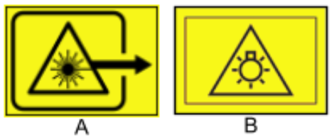
Warning
A - This device is a laser product. Do not deliberately look into the laser beam. This may cause injury to the retina. The use of protective eyewear is normally not necessary. The laser class label is present on the back of the device.
Warning
B - Do not stare at the operating lamp. May be harmful to the eyes.
The device described in this documentation may be operated only by qualified personnel. Qualified personnel are those who, based on their training and experience, are capable of identifying risks and avoiding potential hazards when working with this device.
Connecting the Device
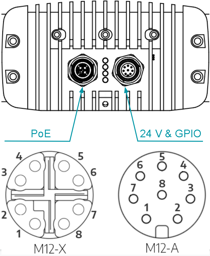
The device can be connected and powered in 2 ways:
Power over Ethernet (Data + Power)

Recommended powering option, using PoE injector and 1 Gbps Ethernet cables
Connect the Ethernet cable from the device to the data + power port on the PoE injector
Connect the Ethernet cable from the data port on the PoE injector to the PC
Ethernet (Data) + 24V (Power & GPIO):
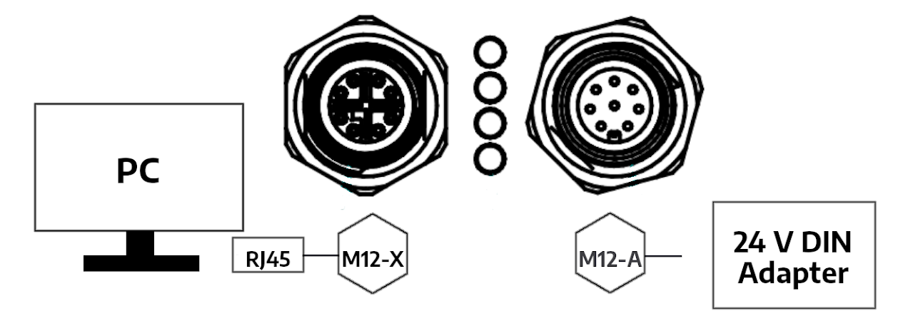
Connect the device by Ethernet cable directly to the PC
Use 24V power adapter|- The power connector provides additional I/O functionality
Disconnecting Device
Always disconnect from the device in PhoXi Control or other applications using the GigE standard before physical disconnection of the device. Make sure the device is not scanning before turning off the device.
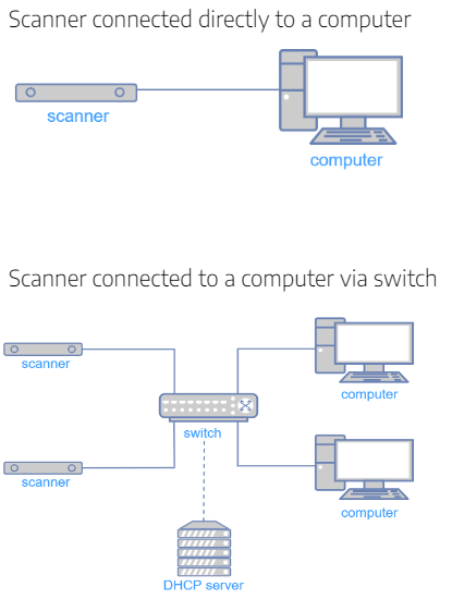
Supported Network Topologies
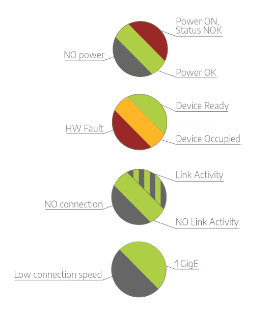
Status LEDs
Different colors of Status LEDs on the back of the device indicate the following states of the device:
M12-A Coded - 24V & GPIO Pinout
Pin |
Pinout |
Function |
|---|---|---|
1 |
DC_IN |
+24 V |
2 |
OPTO_IN2_GND |
laser interlock ground1 |
3 |
GND |
ground |
4 |
OPTO_IN1 |
hardware trigger input signal2 |
5 |
OPTO_IN1_GND |
hardware trigger input ground |
6 |
OPTO_OUT |
hardware trigger output signal2 |
7 |
OPTO_OUT_GND |
hardware trigger output ground |
8 |
OPTO_IN2 |
laser interlock signal1,2 |
1 laser interlock requires a special firmware package
2 5 - 24 V
Powering the device
PoE |
DC |
|
|---|---|---|
PoE Standard |
IEEE802.3at |
— |
Operating voltage Ue DC at the device1 |
min. 55 V |
24 V (20 - 30 V) |
Rated operating current Ie (Imax) |
0.36 A (0.6 A) |
1 A (2 A) |
Minimum power |
33 W |
60 W |
Shielding |
Recommended |
— |
Transfer data rate |
1 Gbit |
— |
Maximum recommended cable length |
20 m (wire cross area 0.14 mm²) |
20 m (wire cross area 0.25 mm²) |
1 accounting for the voltage drop
Mounting Instructions
Warning
Hot surface! The surface of the processing unit becomes hot to touch when the device is in use. Mount the device on a metal mounting plate that will act as a thermal bridge to dissipate the heat or use the carbon body to manipulate the device.
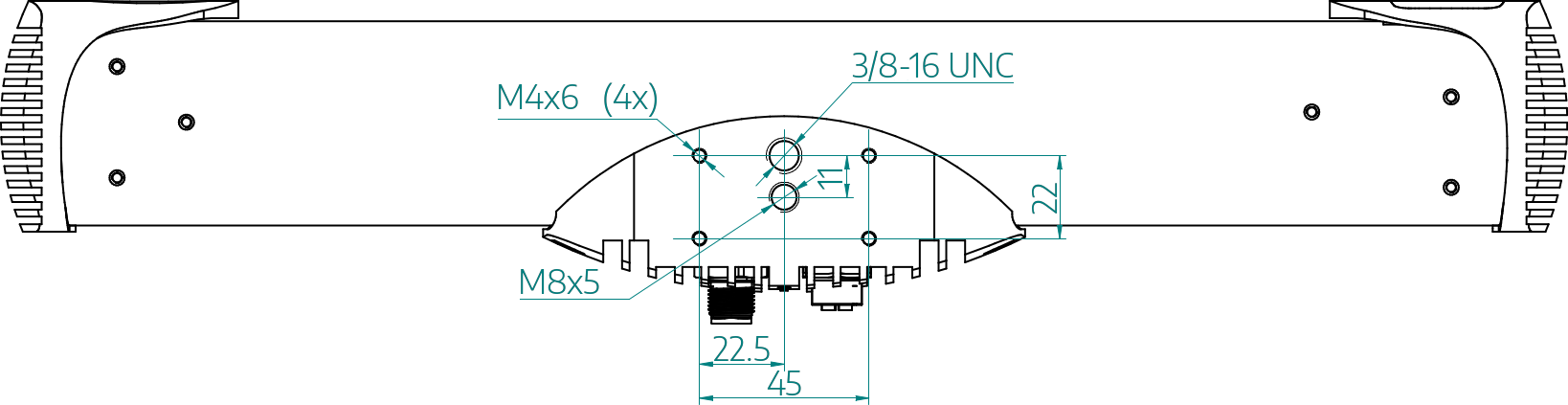
Use 4x M4 screws with a metal mounting plate of suitable size - preferred mounting method for heat dissipation.
Use an M8 screw.
Use a 3/8 - 16 UNC screw with a tripod.
Ensure that mounting construction is rigid enough to avoid vibrations when scanning static scenes (static mode)
Allow clearance around all heatsinks of 25 mm for natural convection cooling.
The full operating temperature of the device is 0 °C to 40 °C
The operating temperature for the optimal scanning performance is 22 °C to 25 °C.
Separate the device from high-voltage devices and devices generating high electrical noise.
Accessories Options
Warranty
Warranty conditions are stated in General Terms and Conditions on the Photoneo website: https://photoneo.com/kb/terms-conditions