Specifying how and where to pick an object is a crucial step in Bin Picking Studio (BPS) solution configuration. Path planning performance and the overall success rate of bin picking depends on finding the most optimal setup.
Bin Picking Studio defines two fundamental entities - the tool point and the gripping point. Together with the defined grasping method, they specify the bin picking routine.
The tool point is a property of the tool (gripper), whereas the gripping points are defined on the object to be picked.
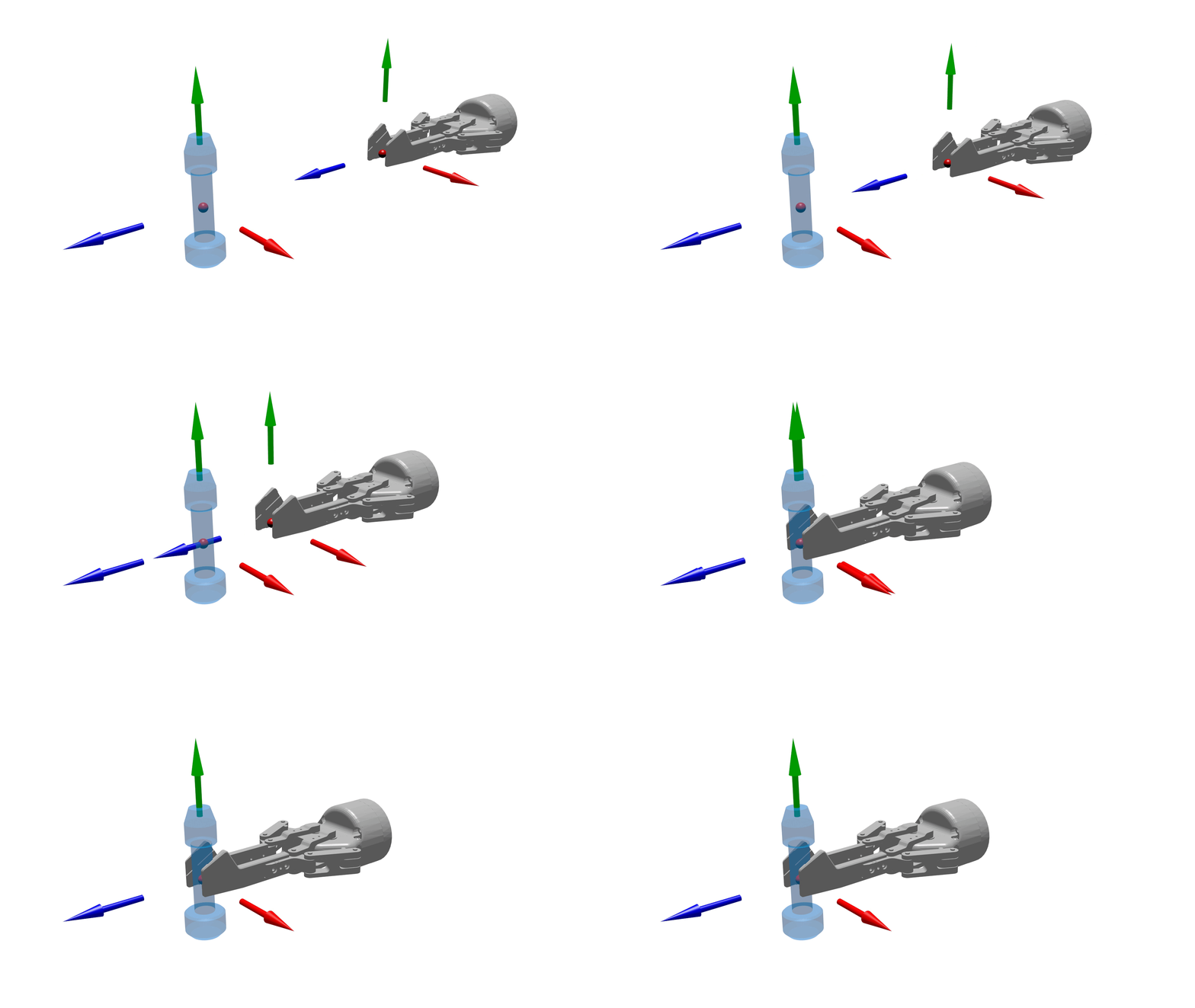
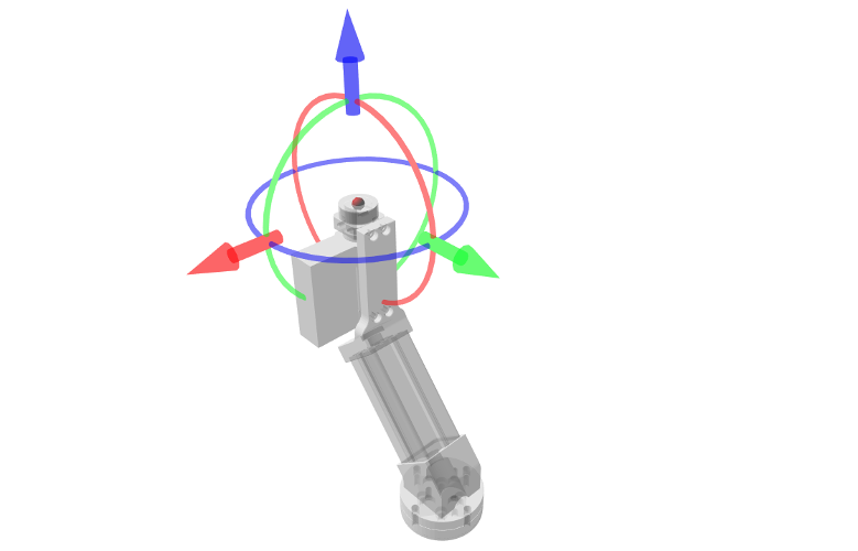
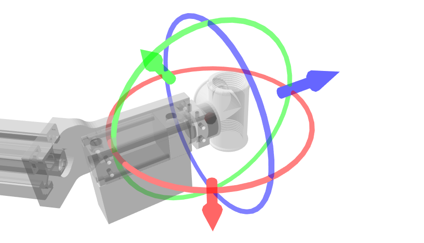
During the grasping action, the tool point and one of the gripping points become one - their coordinate systems are overlaid (see Figure 1 below). The tool point and a gripping point define the place of contact between the gripper and the picked object.
Figure 1 - The alignment of the coordinate system of the tool point with the coordinate system of the gripping point during a grasping action
Incorrectly defined tool point and gripping points may cause unnecessary redundancy of picking configurations and a slow-down of overall bin picking performance.
Contents
1 Definitions
1.1 Tool point
A bin picking routine executed by a robot consists of dozens of trajectory points that the robot’s tool center point (TCP) goes through. The trajectory points, however, do not define the TCP’s location in cartesian space. They are defined in joint space - each point defines the precise angle of rotation of all the individual joints of the robot.
The definition of the TCP is still important though - Bin Picking Studio uses its own tool point definition instead of relying on the TCP as defined on the robotic controller.
The tool point is defined with respect to the origin of the CAD model of the gripper. This origin must be located in the place where the gripper is mounted onto the robotic flange. Its orientation is also important - the Z-axis of the tool point’s coordinate system should point out of the gripper in a positive direction.
BPS currently supports a single tool point definition.
1.2 Gripping point
The locations of suitable gripping points depend on the shape of the picked object itself, the material it is made of, and the gripper used for grasping.
A gripping point is defined with respect to the origin of the picked object’s CAD model.
BPS supports an unlimited number of gripping points for a single picked object.
Note: Specifying a gripping point is only necessary for CAD-based solutions. In an Anypick solution, BPS takes care of finding suitable gripping points automatically.
Remember that changes to the tool point affect how all gripping points are approachable. Changes made to a single gripping point have no influence on the other gripping points.
1.3 Invariance
In addition to an accurate definition of the tool point and the gripping points, it is important to understand another property of the gripper and the picked object - the invariances when rotating around an axis.
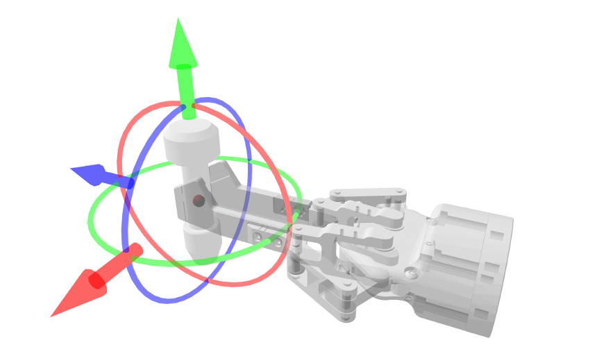
Take a look at the picked object in Figure 2 below. It is symmetrical around its Y-axis (the green arrow). It does matter how the object is rotated if we need to pick it from the top or from the bottom but it is clearly the same when we are picking it from the side with a two-finger gripper. Thus we call this object invariant for any rotation around an axis (axis Y in this particular case).
To leverage symmetries in the picked object, set up invariances for a gripping point to define a series of points along any axis or a combination of axes.
Figure 2 - An axis of invariance of the picked object (as pertaining to a particular gripping point) & an axis of invariance of the gripper (i.e. the tool point)
The tool point of the gripper may also have invariance of its own. Consider the two-finger gripper in Figure 2 above. As illustrated, the gripper is able to grasp the picked object in its original position or when rotated by 180 degrees around its Z-axis (the blue arrow). In contrast to the picked object, this particular tool point is not invariant for any rotation around the symmetry axis but it has precisely two configurations which are the same (invariant) - no rotation and a rotation of 180 degrees.
Setting up correct tool point invariances helps us achieve the best bin picking performance.
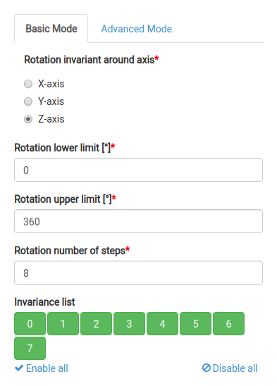
Note: Invariances are generated by splitting the specified range of rotation (Rotation lower limit to Rotation upper limit) evenly into Rotation number of steps. If this split results in the last step (e.g. at 360 degrees) overlapping with the first (e.g. at 0 degrees), these two are considered one and the last one is not shown. In some cases, some steps may not be graspable if the object (or even the gripper) has an uneven feature at some angles of symmetry (consider a symmetrical metallic object to be picked using a magnetic gripper but having one side plastic or holy and thus non-magnetic.) For these cases, some invariances may be easily disabled and as such will not be used for grasping.
1.4 Multiplying invariances
In Figure 2above, when a gripping point has 8 invariances thanks to its rotational symmetry, for example, and the tool point has 2 because it is a two-finger gripper with symmetrical fingers, the total number of ways the picked object can be grasped is 16.
In this example, the invariance axis of the gripping point and the invariance axis of the gripper are orthogonal to each other and so there is no redundancy. This is a valid setup for this scenario.
As illustrated in Figure 3 below, if a flat magnetic tool point or a suction cup is used which is invariant for any rotation around its Z-axis (has multiple invariances set up), and the object it picks is also invariant for any rotation around the same axis, the picked object should not have a gripping point defined with invariances enabled for that axis.
If we were to specify additional invariances on a gripping point around that axis, for example 8, combining these with the tool point’s invariances would result in 64 possible combinations, mostly overlapping ones. This is redundant and thus inefficient for computation in the bin picking pipeline. Redundant invariance definitions will reduce bin picking performance in deployment.
Figure 3 - Incorrect setup - The rotational invariance of the magnetic gripper (left) is along the same axis as the rotational invariance of the gear object being picked (right), which is, in this particular case, redundant
There are cases where setting up invariances around the same axis for both the tool point and gripping point are valid. We just need to be careful not to create unwanted redundancies that would lower bin picking performance.
1.5 Leveraging invariances
The gear object in Figure 3 above may be picked by either its bottom or top surface by the magnetic gripper. This scenario is described in more detail in an example below. In cases such as this, there is a choice of how to set up the gripping points:
We may specify two separate gripping points, one on the bottom surface and one on the top surface. There is no need for invariances because the gripper is already invariant (tool point invariance around the Z-axis). This setup would suffice.
We may choose to leverage the fact that, for the purposes of bin picking with a magnetic gripper, this object is also symmetrical when flipped 180 degrees around any horizontal vector passing through the centroid of this object. Thanks to this property, both gripping points may be defined using one symmetry point with two invariances. In this case, one gripping point would specify both attachment possibilities.
Whereas specifying two separate gripping points is a valid approach, leveraging invariances around a single symmetry point has its advantages. If we need to manipulate the parameters of grasping, for example, we can do this in one place by editing the one gripping point with invariances. We do not need to replicate each setting change in two separate gripping points. Moreover, when the tool point changes, we will have fewer gripping points to adjust to it if we are leveraging invariance definitions.
On the other hand, using separate gripping points gives us the option to set different priorities for them.
2 Example tool points
In the examples below, we are demonstrating the most common tool point setups for two types of grippers.
2.1 Two-Finger gripper
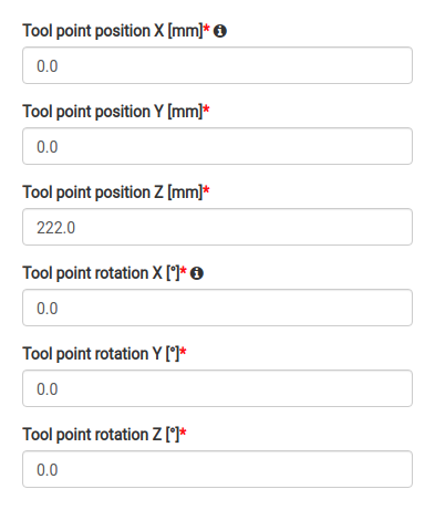
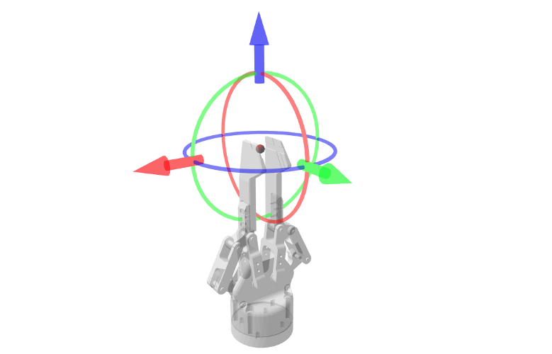
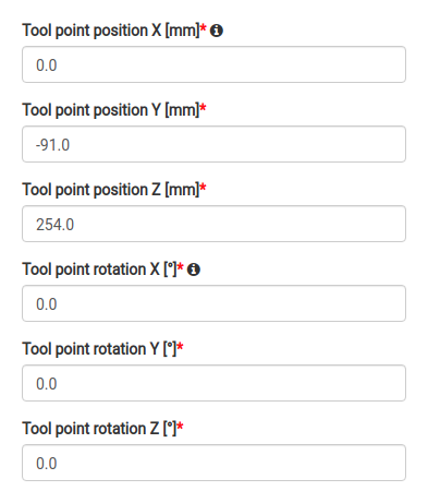
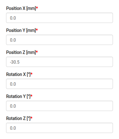
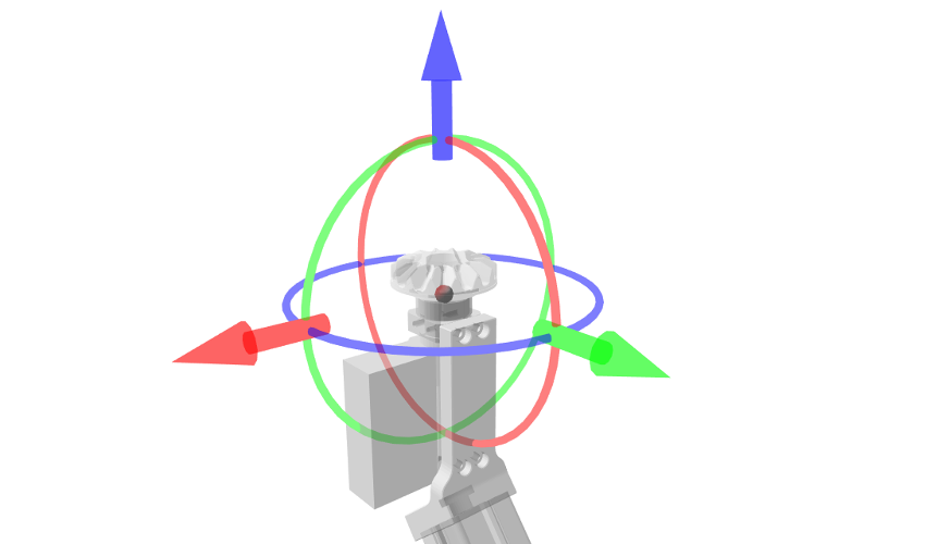
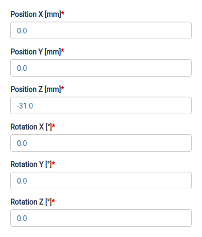
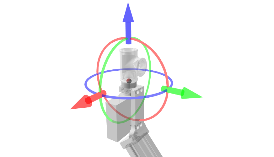
This two-finger gripper has a tool point located between the fingertips as shown in Figure 4 below (the red ball). In this particular example, the tool point is directly above the origin of the CAD model. Therefore, it is easy to specify using an offset on the Z-axis.
Figure 4 - Two-Finger gripper - Tool point definition (left) and its visualization (right)
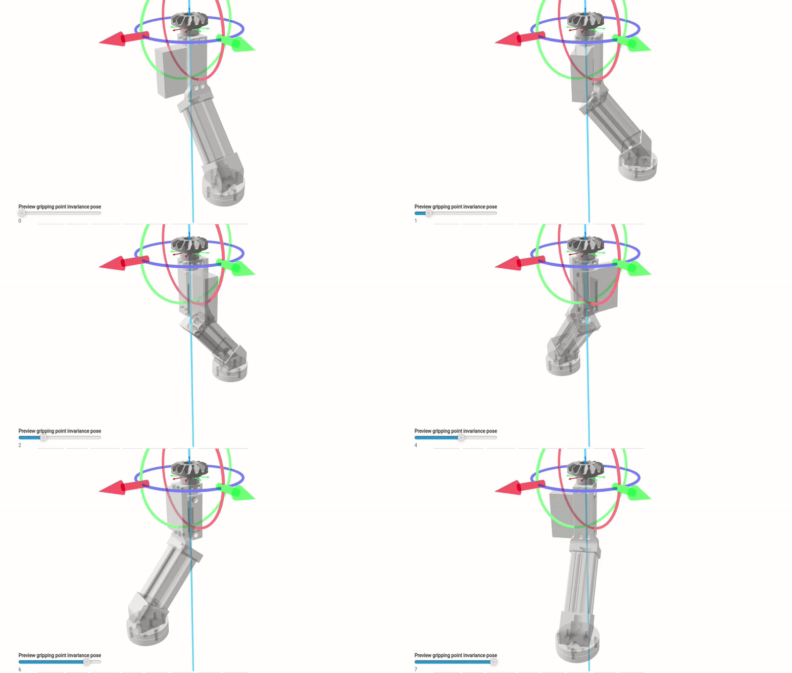
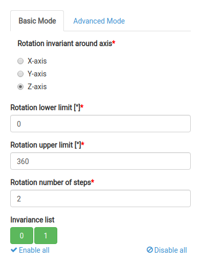
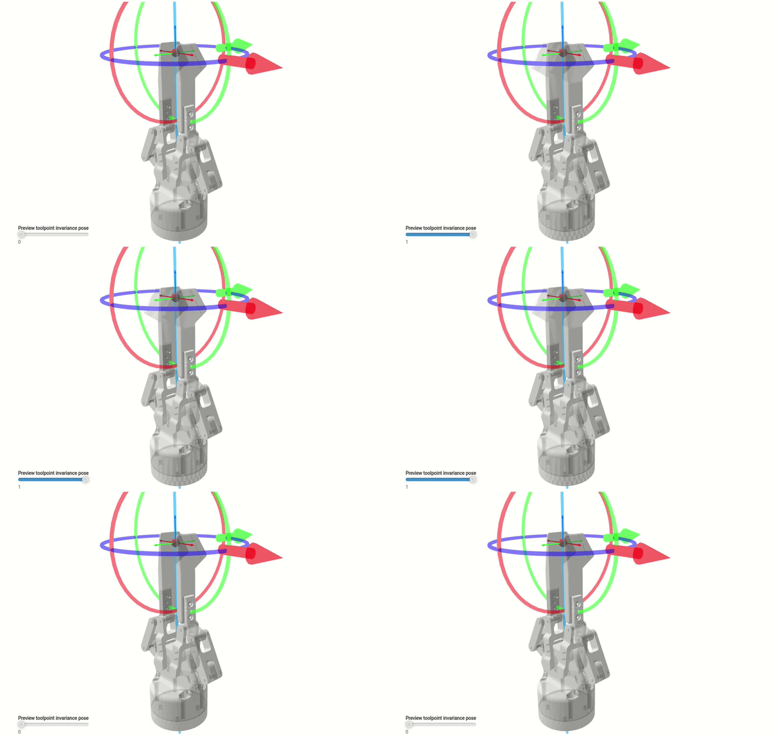
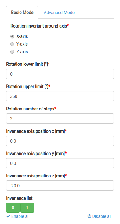
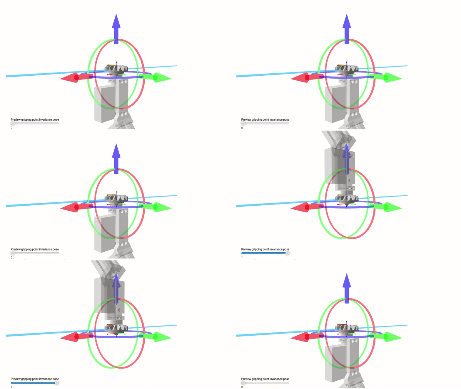
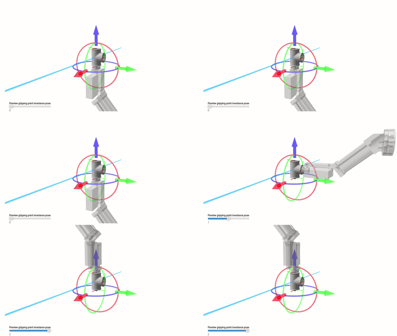
The tool point is invariant for (some) rotations around the Z-axis (the axis of invariance is rendered blue in Figure 5 below). This particular gripper has only two suitable invariant positions and so the parameter Rotation number of steps is set to 2. You can preview the tool point’s invariance poses using the slider in the visualizer.
Figure 5 - Two-Finger gripper - Tool point invariance definition (left) and the visualization of both tool point configurations (right)
2.2 Magnetic gripper
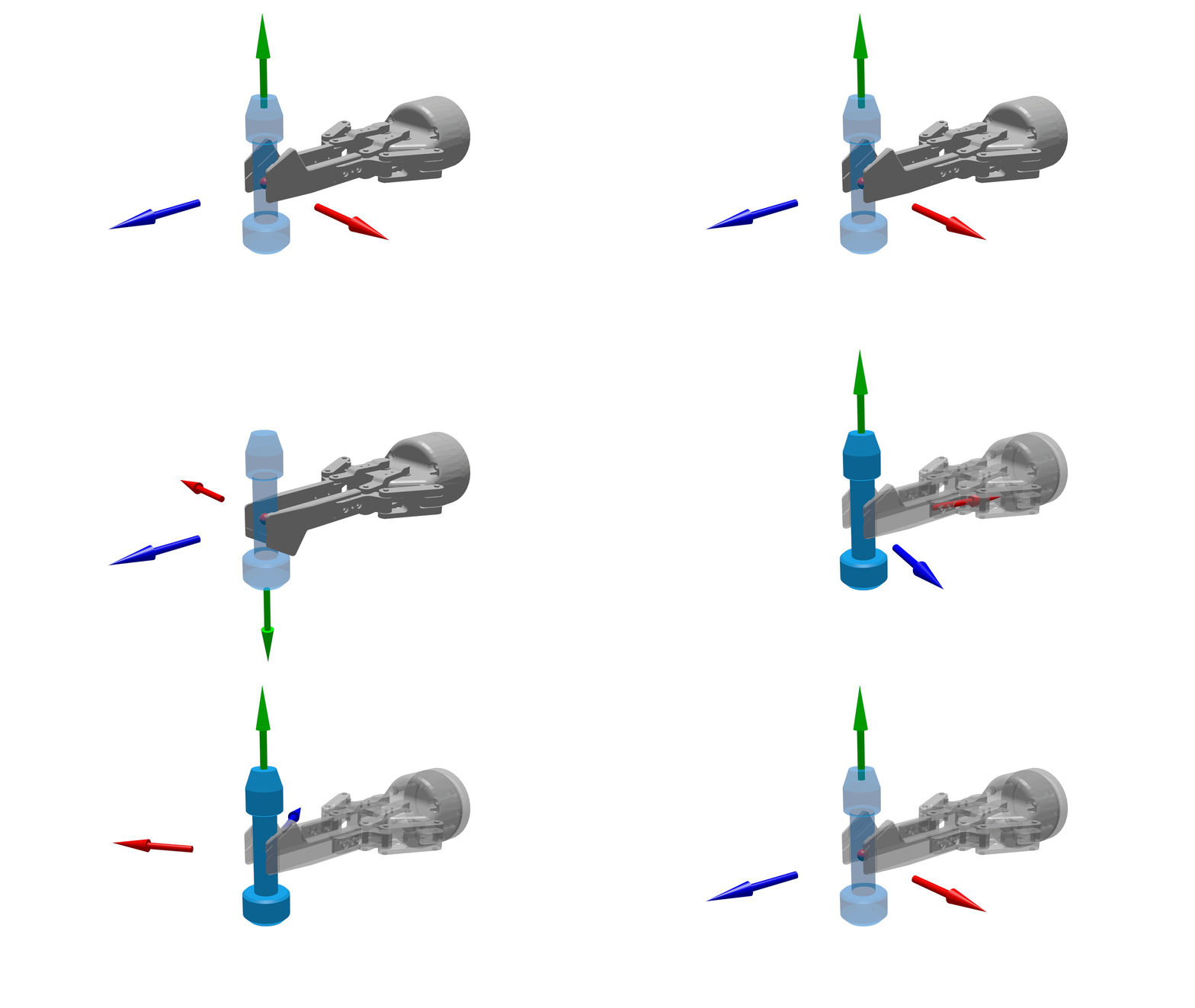
In this example, we will set invariances for a magnetic gripper with a shape resembling a hockey stick. The gripper’s tool point is located in the middle of the contact area of the magnet. Because of the gripper’s eccentric shape, the tool point is offset from the origin not only in the Z-axis but also in the Y-axis.
Figure 6 - Magnetic gripper - Tool point definition (left) and its visualization (right)
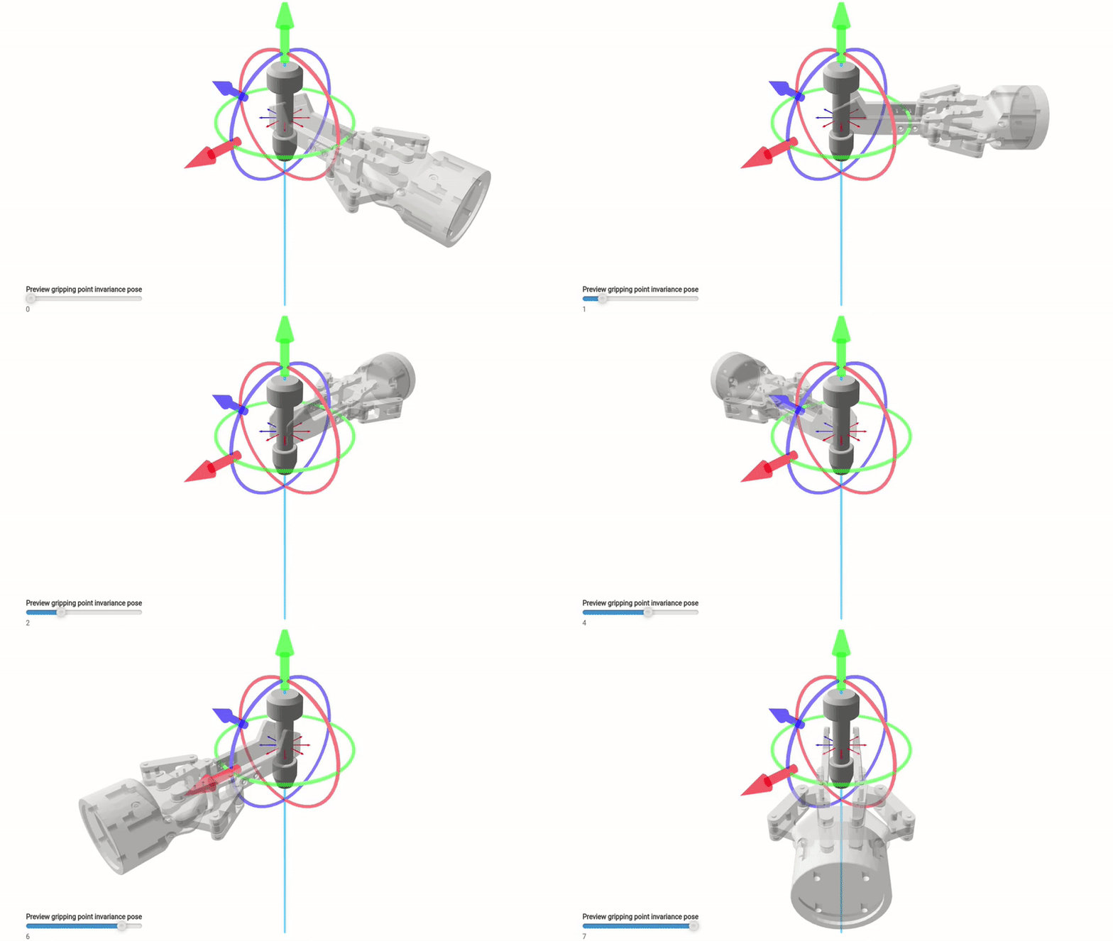
The tool point is invariant for any rotation around the Z-axis because the contact area is a flat round magnetizable disc. It does not matter how the gripper is rotated around the Z-axis of the tool point. The contact area is always the same because its contact plane is perpendicular to the Z-axis of the toolpoint, i.e. the axis of invariance (rendered blue in Figure 7 below). The rotation range is unlimited (the default limits are honored) and as such, this gripper has infinite suitable positions. With a higher value of Rotation number of steps, the probability of successful path planning increases. On the other hand, values set too high slow down the bin picking performance. The default value of 8 rotation steps is adequate in this case. You can preview the tool point invariance poses using the slider in the visualizer.
Note: The same recommendations apply to a single suction-cup gripper if the suction cup were in the place of the magnet.
Figure 7 - Magnetic gripper - Tool point invariance definition (left) and the visualization of all tool point configurations (right)
3 Example gripping points
In the examples below we demonstrate how to define suitable gripping points for several picked objects based on the type of gripper used for grasping.
3.1 Cylindrical object #1
We wish to pick an object of cylindrical shape using a two-finger gripper. In this scenario, the most suitable gripping point lies in the middle of the object on the axis around which the object is symmetrical, as shown in Figure 8 below.
Figure 8 - Cylindrical object - Gripping point definition (left) and its visualization (right)
To be able to pick an object from multiple angles, several gripping points may be defined in different places on the gripper. However, the object is symmetrical around its Z-axis, and so it is simplest to define a single gripping point and enable rotation invariance around the Z-axis for it. The default values are adequate in this case. You can preview all possible gripper poses for this gripping point using the slider in the visualizer.
Figure 9 - Cylindrical object #1 - The definition of gripping point invariance (left) and the visualization of all gripping point configurations (right)
3.2 Cylindrical object #2
This gear object of cylindrical shape will be grasped by a magnetic gripper. A magnetic gripper requires that the ideal place of contact should be a flat area on the object to ensure the most reliable grip. The object has two such surfaces - the top and the bottom face. The gripping point is defined in the middle of the bottom face as shown in Figure 10 below.
Figure 10 - Cylindrical object #2 - The definition of a gripping point (left) and its visualization (right)
To ensure that these objects may be picked reliably when they are randomly orientated in a bin, a second gripping point should be defined on the top face of the model. However, for the purposes of gripping point definition, the object is symmetrical around both its X and Y axes. As explained earlier, it is beneficial to leverage this symmetry and define this pair of gripping points as invariances 180 degrees apart around a single point of symmetry.
To achieve this, the value of parameter Rotation number of steps must be set to 2 (to cover both the top and the bottom face) and the z-position of the axis of invariance must be offset to go through the centroid of the object. By default, the z-position of the invariance is 0, which is in the origin of the object and as such unsuitable in this case. We need to specify the point of symmetry in the centroid of this particular object’s CAD model. You can preview all the possible gripper poses for this gripping point using the slider in the visualizer, as illustrated in Figure 11 below.
Note: The gripping point should avoid having invariances defined around the Z-axis in this scenario. The gripper should already have its own invariances specified around the same axis because it is invariant as to how it attaches to any gripping point. Specifying additional invariances on the same axis for the gripping point itself would cause redundancy and slow down computation, as explained earlier.
Figure 11 - Cylindrical object 2 - The definition of gripping point invariance (left) and the visualization of both gripping point configurations (right)
3.3 T-shaped object
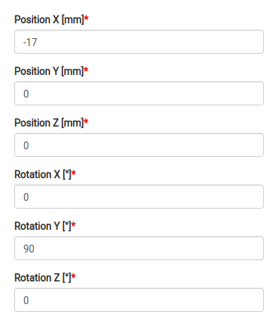
This common T-Fitting object may be picked by a magnetic gripper. The openings of the T-Fitting can be considered as suitable grasping points as there is enough surface area in a plane in each of them.We choose to define a gripping point in the middle of the bottom opening as shown in Figure 12 below.
Figure 12 - T-shaped object - The definition of a gripping point (left) and its visualization (right)
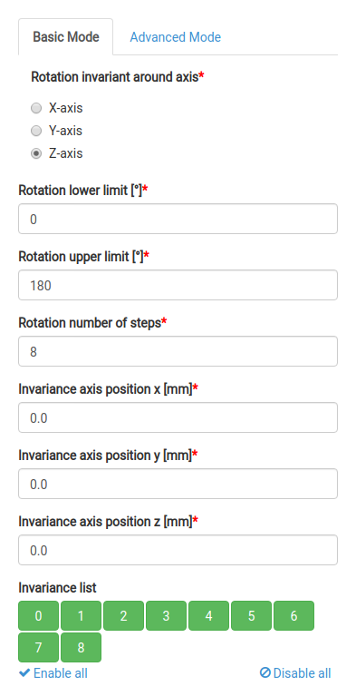
Once again, more gripping points may be defined, one for each opening. But since the object is partially symmetrical around its X-axis (because each opening is equidistant from the centroid), this symmetry could be leveraged for invariances. Because of the shape of the object (it is not completely symmetrical), we must limit the range of symmetry. This can be easily done by setting the parameter Rotation upper limit to 180 degrees. Since the origin of this particular CAD model is in its centroid and the axis of invariance goes though it by default, all that’s left to do is choose the correct Rotation number of steps, which is 2.
Note 1: As explained earlier, no rotational invariances should be specified on the Z-axis (the blue arrow) for this gripping point if the magnetic gripper itself is already invariant on the same axis.
Note 2: We could define the same behavior by keeping the default (full) range of symmetry (0-360 degrees) with 4 Rotation number of steps and disabling the one invariance on the incorrect side of the object in the invariance list (e.g. invariance 3 equivalent to 270 degrees, if that is indeed the unsuitable side). The resulting performance of this approach would be equivalent to the limited-range setup outlined above.
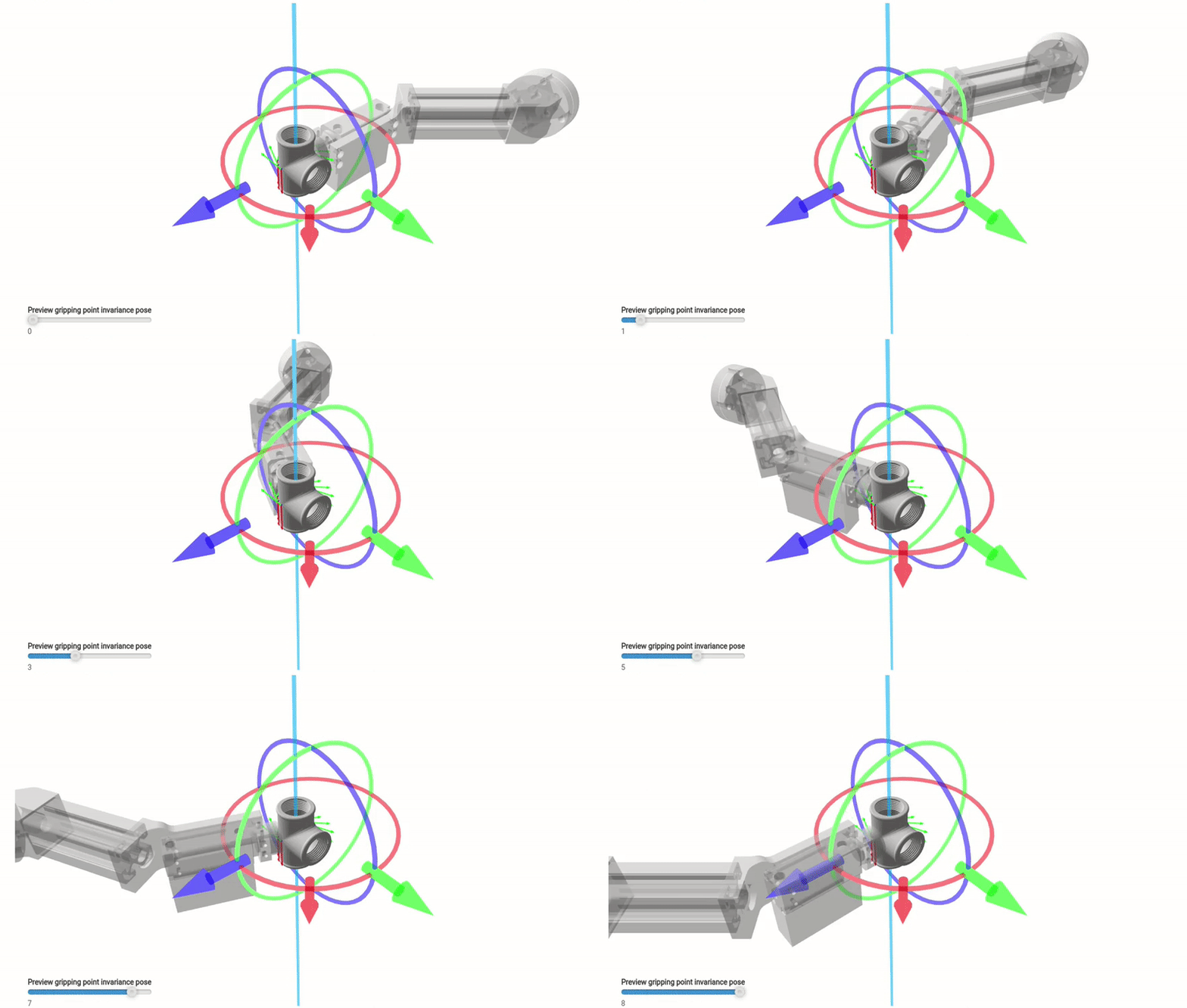
Figure 13 - T-shaped object - The definition of gripping point invariance (left) and the visualization of all gripping point configurations (right)
Unordered objects in a bin can lie in any possible orientation. Even though we have specified three invariances of a gripping point, it is unlikely that we will be able to pick all objects with this setup. Whenever all three openings are not pickable by the robot (e.g. they are occluded, at a wrong angle, etc.), BPS will be forced to leave the object in the bin.
Therefore, we must ensure that we have a gripping point defined for every possible object rotation. There is no more invariance left for us to leverage on the first gripping point so we are forced to define a second independent gripping point. The second gripping point will be defined with invariances on the axis going through the two opposite openings of the T-Fitting (the X axis in our case, perpendicular to the Z axis of symmetry of the previously defined gripping point). The gripping point is offset so that it lies on the surface of the object (see Figure 14 below).
Figure 14 - T-shaped object - The definition of a second gripping point (left) and its visualization (right)
With the gripping point defined in this way, the object is again partially invariant around the X-axis. We need to exclude the angles where the middle opening is located. We can do so either by limiting the Rotation upper limit to 180 degrees or by disabling the invariances for which the gripper would collide with the picked object (i.e. the middle opening of the T-Fitting). Both solutions result in equivalent bin picking performance.
Figure 15 - T-shaped object - The definition of the invariance of the second gripping point (left) and the visualization of all gripping point configurations (right)