PhoXi Control User Manual
PhoXi™ Control 1.17
User Manual
User Manual for PhoXi Control version 1.17 based on PhoXi Control version 1.17.0.
All rights reserved.
No part of this publication may be reproduced, stored in a retrieval system, or transmitted in any form or by any means, electronic, mechanical, photocopying, recording, or otherwise, without prior written permission of the publisher.
Copyright © 2014-2024 by Photoneo s.r.o., Bratislava, Slovakia
Copyright © 2026 by Zebra Technologies Slovakia s.r.o., Bratislava, Slovakia
Photoneo™, PhoXi™ Control, PhoXi™ 3D Scanner, MotionCam-3D are registered trademarks of Zebra Technologies Slovakia s.r.o.
Microsoft, Windows, Windows 10, and Visual Studio C++ are either trademarks or registered trademarks of Microsoft Corporation.
Linux is a trademark of Linus Torvalds.
NVIDIA and CUDA are either trademarks or registered trademarks of NVIDIA Corporation.
OpenGL is a trademark of Silicon Graphics, Inc.
All other nationally and internationally recognized trademarks and tradenames are hereby recognized.
About This User Manual
This manual is intended for users who want to familiarize themselves with PhoXi Control software for MotionCam-3D, MotionCam-3D Color, PhoXi 3D Scanners, and Alpha 3D Scanners. PhoXi Control provides both a graphical user interface (GUI) and an application programming interface (API).
The MotionCam-3D (Color) is a high-resolution and high-accuracy 3D camera that uses a patented CMOS sensor and Parallel Structured Light technology developed by Photoneo. It provides the scanning quality of structured light devices with the ability to scan static and dynamic scenes at the speed of Time of Flight devices. Additionally, output from the RGB camera unit on the color models is mapped on the point cloud, adding an important layer of information for further processing. PhoXi 3D Scanner is a compact yet powerful 3D scanner with state-of-the-art performance in terms of precision, noise, and overall efficiency. It can be used for scanning a wide variety of objects, making it a universal tool for all kinds of industrial applications, mainly automated object manipulation and inspection. Alpha 3D Scanner takes advantage of the structured light technology, providing high-quality 3D point clouds for a great variety of machine vision tasks, making it a perfect choice for scanning large objects with a simple shape, such as boxes or containers in measurement, inspection, and similar applications.
This manual is based on the Photoneo 3D Sensors on firmware version 1.17. Using a Photoneo 3D Sensor on a different version may result in slight differences. It is recommended to use the newest firmware version available at Firmware Updater. Consult the Versioning Guide to see the newest firmware version for your device.
Visit www.photoneo.com for the most up-to-date information and documents.
Please read the PhoXi Control User Manual before using the software, and the Photoneo 3D Sensor User Manual to become familiar with the safety and assembly instructions before using the devices.
Introduction
This user manual will first guide you through the use of PhoXi Control Graphical user interface (GUI) and the API, and then provide a quick scanning guide with references to further resources. Additionally, alternative ways of operating Photoneo 3D Sensors are referenced or described.
Photoneo sensors can be operated via:
PhoXi Control
GUI
API
GenICam (discontinued)
GigE Vision protocol
PhoXi Control application enables users to control Photoneo 3D Sensors manually via the GUI or by a computer program using the provided API or GenICam interface. Alternatively, Photoneo sensors can run in GigE Vision compatible mode in which PhoXi Control cannot be used.
PhoXi Control
The GUI is primarily used to set up the scanning environment, configure the device parameters, and test the output. In addition, the GUI can also be used as a powerful debugging tool for development with the API, since the calls to the API trigger the same response in the GUI as the user inputs. After triggering the scan by calling the API method, the application will execute the scan, send it as an output of the call, and display it simultaneously on the GUI.
The API has been designed to serve as a central platform for the development of custom applications. To facilitate the development process as well as to reduce computing demands, all 3D data computations are performed on the device itself. The postprocessing of the data (e.g. Localization of object) happens on the user’s computer.
GenICam interface (discontinued) 
Important
GenICam interface was discontinued and removed from PhoXi Control 1.16.4 and onward.
The Generic Interface for Cameras standard is the base for plug-and-play handling of cameras and devices. It was developed by the European Machine Vision Association (EMVA)
GenICam support is provided via the GenTL library that works as a wrapper around the PhoXi Control C++ API. PhoXi Control has to be running in order to use the GenICam interface.
The available examples for Python and Halcon support can be found in the installation directory:
On Windows OS, the path to the GenTL directory is usually:
Program Files/Photoneo/PhoXiControl-1.16.x/API/Examples/GenTL
On Linux OS, the path to the GenTL directory is usually:
/opt/Photoneo/PhoXiControl-1.16.x/API/GenTL
User guides for GenICam integrations contain more detailed information and requirements for running the examples.
GigE Vision 
GigE Vision functionalities can be turned on and off. For that please download and install the necessary utilities, that you can find on the corresponding links:
GigE Vision utilities for Windows : www.photoneo.com/dl/gigev-utils-win
GigE Vision utilities for Linux: www.photoneo.com/dl/gigev-utils-lin
Common Terms
Clarification of several terms used in this document.
Photoneo 3D Sensor |
General term for PhoXi 3D Scanner or MotionCam-3D (Color). |
device |
General term for PhoXi 3D Scanner or MotionCam-3D (Color). |
MotionCam-3D |
General term for MotionCam-3D devices including the MotionCam-3D Color if not stated otherwise |
2D camera |
Refers to the 2D camera unit inside PhoXi 3D Scanners. |
image sensor |
‘Image sensor’ refers to the CMOS sensor inside the 2D camera unit. More information about camera components can be found in Photoneo 3D Sensors User Manual |
RGB camera |
Refers to the 2D RGB camera unit inside the MotionCam-3D Color and Phoxi 3D Scanner Gen3. |
Getting Started
Computer Requirements
Please ensure that your computer meets the minimum recommended requirements in order to run PhoXi Control smoothly.
Processor |
Any x64 architecture, Intel or AMD but Intel Core i7 or Ryzen 7 for best performance. (Processor performance affects the responsiveness of the application) |
Operating system: |
Only 64-bit platform Windows 10 / 11 Ubuntu 18 / 20 / 22 / 24 |
RAM: |
Recommended 16 GB (minimum 2 GB for the application connected to 1 device) |
SSD: |
128 GB (Minimum 4 GB free disk space) |
GPU: |
GeForce GTX 1060 3 GB or similar external graphics card with OpenGL v 3.0 support. |
Note
Photoneo 3D Sensors have a very high resolution mode producing up to 3 million 3D points, therefore the requirements made on the graphical performance of your graphics cards are higher. Old or slow graphics cards can reduce the performance of the 3D viewer.*
Supported Compilers
To use the API, the following compilers are supported:
Windows OS:
Visual Studio 14 2015 Win64
Visual Studio 15 2017 Win64
Visual Studio 16 2019 Win64
Visual Studio 17 2022 Win64
Ubuntu 18:
g++ 7.4.0
Ubuntu 20:
g++ 9.3.0
Ubuntu 22:
g++11.3.0
Ubuntu 24:
g++ 13.2.0
Installation
Download the latest version of PhoXi Control: www.photoneo.com/downloads/phoxi-control
By installing and using PhoXi Control, you agree to the End User License Agreement (EULA), which can be found in the installation directory.
While the installer will prompt you to uninstall any existing version of PhoXi Control, this step can be ignored as Multiple versions of PhoXi Control can be installed on one computer. However, only one instance can run at a time.
To install PhoXi Control on Windows, proceed as follows:
Double-click the downloaded
*.exeinstallation file.Follow the setup wizard and restart the computer if this is your first installation of PhoXi Control.
Run PhoXi Control as a standard Windows application. The application automatically starts after the computer starts.
Note
The user is able to install PhoXi Control with or without the included file camera examples or the API. This can be changed during the Choose Components part of the installation process.
Shortcut folder:
C:\\ProgramData\\Microsoft\\Windows\\Start Menu\\Programs\\Photoneo PhoXi Control
Installation folder:
C:\\Program Files\\Photoneo\\PhoXiControl-<version>
Application data folder:
%AppData%/PhotoneoPhoXiControl/
To install PhoXi Control on Ubuntu, proceed as follows:
Unpack the downloaded *.tar file.
$ tar -xvf PhotoneoPhoXiControlInstaller-<version>-Ubuntu[22 20 18]-STABLE.tar.gz
Make the file executable and then execute with sudo. The installation requires the user to accept EULA, to do this automatically, pass the –accept flag to the installer script.
$ chmod +x PhotoneoPhoXiControlInstaller-<version>-Ubuntu[22 20 18]-STABLE.run

$ sudo ./PhotoneoPhoXiControlInstaller-<version>-Ubuntu[22 20 18]-STABLE.run

$ sudo ./PhotoneoPhoXiControlInstaller-Ubuntu-<version>.run --accept /opt/Photoneo/PhoXiControl-<version>
Successful installation output will show you the installation path and will ask you to reboot.
Restart your computer.
$ sudo reboot
Run PhoXi Control from a command line or from a launcher.
$ PhoXiControl
Installation folder:
/opt/Photoneo/PhoXiControl-<version>
Application data folder:
/home/<username>/.PhotoneoPhoXiControl
Multiple Versions of PhoXi Control
Multiple versions of PhoXi Control can be installed on one computer. This is achieved by choosing different installation directories during the installation. The process is as follows:
Windows
On Windows, the installer asks for a path where the application should be installed. By default, this path is:
C:\\Program Files\\Photoneo\\PhoXiControl-<version>
When another version of PhoXi Control is being installed, a different path should be specified, for example:
C:\\Program Files\\Photoneo\\PhoXiControl-custom
Linux
Ubuntu installer automatically installs PhoXi Control in the following folder:
/opt/Photoneo/PhoXiControl-1.16.x
To install PhoXi Control to a different folder, pass it as an argument to the install script:
$ sudo ./PhotoneoPhoXiControlInstaller-1.16.x-Ubuntu.run /your/custom/path
To match the old behavior of the Ubuntu installer use the original location:
$ sudo ./PhotoneoPhoXiControlInstaller-1.16.x-Ubuntu.run /opt/Photoneo/PhoXiControl
Important
PhoXi Control path environment variable is set to the latest installed version of PhoXi Control, not the most recent PhoXi Control version (Example: User installs PhoXi Control 1.16 and then installs PhoXi Control 1.12). This may affect access to certain features only available in the newest release and are dependent on the path defined in the environment variable.
Note
Starting with PhoXi Control 1.17, a warning notification appears if an application utilizing a newer version of the PhoXi API attempts to connect to a running instance of PhoXi Control. This alert is designed to prevent unexpected behavior, communication errors, or missing settings that may occur due to version mismatches between the API client and the host application.

Running the Application
By default, PhoXi Control starts automatically after the operating system is started. Users can change the default application behavior by setting up specific environment variables or by command line parameters.
Disabling GUI or 3D Viewer
Disabling GUI or the 3D Viewer is used mainly in the following situations:
Need to save computer resources or when the computer has insufficient performance (3D Viewer)
Applications with their own GUI using only the API
Desired behavior |
Action needed |
Permanently disable GUI |
Set environment variable: |
Permanently disable the 3D Viewer only |
Set environment variable: |
Temporarily disable GUI |
Run script:
> %PHOXI_CONTROL_PATH%\\bin\\support\\PhoXi_Control_as_background_process.bat
$ /opt/PhotoneoPhoXiControl/bin/support/RunPhoXiControlOnBackground.sh
|
Temporarily enable GUI (when permanently disabled by the environment variable) |
> %PHOXI_CONTROL_PATH%\\bin\\support\\PhoXi_Control_enable_gui.bat
|
Command Line Parameters
PhoXi Control can be started with the following command line parameters:
-minimised
PhoXi Control will be started minimized.
-lock
Used to lock the application against unauthorized use. The application will ask you to set up a password and then to restart. Users are prompted to enter a password every time they start the application. The API can connect to the device only after the password is entered.
-unlock
Removing the authorization request after the application startup. The application prompts you to enter the password and then restarts. This means PhoXi Control can be used without authorization.
-kill
Any instance of PhoXi Control will be switched off.
-forceRun
Used together with -kill. While -kill alone stops all running instances of PhoXi Control, additional argument -forceRun ensures that a new instance of PhoXi Control will be started as next.
Example command:
PhoXiControl -kill -forceRun
Graphical User Interface
Overview
The initial window of the application is called Network Discovery. It displays a list of all the devices available on the network. A new connection to the device opens a new Device window. Device windows can be organized by dragging the window title. The application minimizes itself into the system tray. To close the application, use the Menu or right-click on the system tray icon and select the option to Turn off PhoXi Control.
The version of the PhoXi Control is displayed in the title bar of the GUI window.
Drop-down menus
This chapter explains the use of drop-down menu items.
Menu

Network Discovery
Opens the Network Discovery window. After a successful connection to the device, the Network Discovery window is usually hidden in the background.
Open File Camera
Loads 3D scans in *.praw format into a new File Camera, which remains available until the application is shut down.
Add device via Address
Allows adding Photoneo 3D Sensor into PhoXi Control via its IP address
Lock GUI
Option to protect GUI against unauthorized use.
Turn Off PhoXi Control
Shuts down the application. (Using the standard close window button will only minimize the application).
3D Cameras
A list of active devices. Allows switching between windows of the connected devices or virtual File Cameras.
Languages

Switch between supported languages.
Tools

Marker Patterns
This option opens a directory containing folders with marker patterns and their metadata.
Marker patterns are used for changing the coordinate space and device calibration (multiple devices together, hand-eye calibration, calibration with an external 2D camera)
Marker patterns come in 5 sizes that are intended for different scanning distances. The applicable scanning distances for each pattern are stated in the name of the corresponding pdf file.
This option opens a directory containing folders with marker patterns and their metadata.
Marker patterns are used for changing the coordinate space and device calibration (multiple devices together, hand-eye calibration, calibration with an external 2D camera)
Marker patterns come in 5 sizes that are intended for different scanning distances. The applicable scanning distances for each pattern are stated in the name of the corresponding pdf file.
Options

Switching between different color themes.
Disabling default warning behavior.
Reset application look
The application remembers your preferences for showing UI components. Use this function to reset PhoXi Control to the default layout. Useful mainly when switching between monitors with different DPI and resolutions.
Help
Switch to Admin

This function is only used by Photoneo staff during remote sessions to temporarily set admin privileges.
About
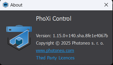
Displays the current PhoXi Control application version and links to the Photoneo web page.
Third Party Licenses button displays a comprehensive overview of the 3rd party licenses.

Network Discovery

The Network Discovery window lists all available devices on the network. After the application starts, please wait a moment until all devices are found, or click on the refresh button in the upper left corner above the displayed devices.
If your device is not listed, please make sure that it is turned on and connected to the network. After a short time, the device will appear on the list. The time required to discover a newly powered device should be under 3 minutes. The time required to discover the device after it was disconnected or the connection was lost should be under 45 seconds.
If no device is shown on your list, please check your network configuration. See the chapter Configuring Device Network Settings for more information.
Selecting a device will display its details such as Name, Description, Configuration, Status, and ID, as well as its network settings, firmware version and model.
Configuration shows the hardware specifications of the given device. Possible tags you can see in the Configuration field are:
Alpha - represents the Photoneo Alpha 3D Scanner
Color - represents the devices with built in RGB camera
Red - represents the color of the laser
Blue - represents the color of the laser
LC2 - represents the Laser Class 2 (used with Photoneo Scanner Gen 2 and MotionCam-3D)
LC3 - represents the Laser Class 3 (used with Photoneo Scanner Gen 2 and MotionCam-3D)
GigE-V - represents the possibility to connect to the device through GigE-V
Interlock - represents the activation of the interlock feature
#MP - represents the maximal supported resolution of the device
Through API, this information can be found under the name “features”. Configuration and features are only available for PhoXi Control version 1.16.2 and higher, as well as firmware version 1.16.2 and higher.
It is possible to “Pin Device” by right-clicking a device in the list. Pinned device will always show on the top of the list. It is also possible to pin a File Camera.

Not all information is available for File Cameras or for devices with an older firmware version. For example, a comment field in the network discovery allows the user to describe the device with a custom message (up to 1024 characters). This is possible only for devices with firmware versions higher than 1.9.0. A comment can be added by right-clicking the Comment and selecting Edit comment.
The status field has three different “Occupied” states :
Occupied by me (via PhoXi Control): Indicated simply as “Occupied” (means the user is already connected)
Occupied by someone else (via PhoXi Control): Displayed as “Occupied” with a red box showing the IP address
Occupied via GigE Vision interface: Displayed as “Occupied” with a red box labeled “GigE Vision” (and the IP address if provided by the device).
IPv4 and IPv6 address rows contain dynamic interface labels. The labels dynamically change color: red for non-routable addresses, orange for sub-1Gbps interface speed, and blue for normal operation (1Gbps).
Device States Overview
The following list represents all the possible device states. It is only possible to connect to a device in Ready state.
Not started |
The device has just been plugged in or was restarted. After a few seconds, the status will change to Starting. |
Starting |
The device is starting its operating application. After a few moments, the status will change to Ready. |
Ready |
The device is ready for a new connection. |
Occupied |
The device appears as occupied after the connection is established. Only one connection at a time is permitted. It is not possible to connect to an occupied device. |
Terminating |
The device is being terminated after the user disconnects from the device. After a few moments, the status will change to Starting and Ready. |
This list can also be found in the lower left corner of the Network Discovery window.
Connecting to the device

To connect to a device, simply double-click on the device name or select it and click Connect. It usually takes about 2-5 seconds for the device to connect; however, based on the internal state of the device, it can take up to 1 minute. Once the device is connected, a new Device window will open and its status in Network Discovery will change from Ready to Occupied. Therefore, if you share a device with other users, make sure you disconnect from it after you finish using it.
Please ensure that you are using a wired network connection to the device. WIFI connections are not recommended due to lower speed and reliability.
Relationship Between GUI and API
Connection to the device via API causes the GUI to open the Device window similar to when connecting via the GUI. When you connect to the device through the GUI, it is possible to work with the device through API.
File Cameras
Every 3D scan captured by PhoXi 3D Scanner or MotionCam-3D can be saved into a Photoneo RAW ( *.praw) file. The main advantage of this native format is that it contains all the information about the scanning configuration and additional information about the device. All other formats can be exported from *.praw files.
Additionally, dynamic scans taken by MotionCam-3D can be saved into a Photoneo MotionCam-3D RAW (*.pmraw) file. This format is capable of creating a file camera consisting of a single file but containing many scans.
Single or multiple *.praw files can be loaded into PhoXi Control either by using the menu or by dragging & dropping the files anywhere on the GUI. Opening N *.praw files will create a new virtual device called File Camera. This virtual device behaves in a very similar way to a regular device. In case of drag-and-dropping multiple *.praw files or opening a *.pmraw file, you can use “Previous frame” and “Next frame” buttons, which replace the “Trigger” button, to cycle through the frames.
While looking at the last scan, you can press Right Arrow to seamlessly move to the first scan. Respectively, you can move to the last scan by pressing Left Arrow, while looking at the first scan.

PhoXi Control already contains 2 example file cameras, which contain 1 or more captured frames and can be used for testing purposes.
Note
The scanning parameters for File Camera are read-only, as these scans have already been taken and processed.
Network Discovery window offers specific options for File Cameras when right-click is used or by using a keyboard shortcut:
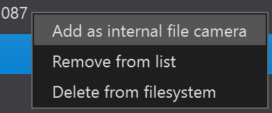
Add as internal file camera
Internal File Camera remains in Network Discovery even after you restart the PhoXi Control application. Otherwise, the File Camera is present only until the end of the application.
Remove from list (Delete key)
This option will remove the File Camera from the list of devices, but keep underlying files on disk.
Delete from the filesystem (Shift + Delete keys)
This option will remove the File Camera from the list of devices and also delete underlying files from the disk.
Setting the order of scans in an internal file camera
After creating an internal file camera using a group of scans, it is possible to define the order of the loaded scans using an order.cache file in the directory of the internal file camera which can be found at:
%AppData%/PhotoneoPhoXiControl/File3DCameras/<file camera name>
Create a file order.cache and open it in a text editor. The order of the scans being loaded in the internal file camera can be defined as follows:
Defining the order by name (alphabetical order)
Line 1:
order_by_name
Defining the order by the last modified date/time
Line 1:
order_by_modified_timecustom
Defining a custom order (files not mentioned will be skipped)
Line 1:
scan_1.prawLine 2:
scan_14.praw
Note
The file camera needs to be set to an Internal File Camera in order to order.cache config file to affect the order. Scans loaded to PhoXi Control by Menu → Open File Camera or by dragging the scans will be normally loaded in the order they were selected in their original directory.
Scanning Settings and *.praw Files Compatibility
The scanning settings are applicable to the device depending on its FW version. A *.praw file contains complete data about the scan, including scanning settings. It needs to be noted that older versions of PhoXi Control might not display all parameters of devices with newer FW.
Offline Inspection of P(M)RAW Files
Users can inspect and extract image data from proprietary Photoneo RAW files (.praw and .pmraw) offline, without requiring an active instance of PhoXi Control or a connected physical device.
PhoPrawExtractor — a command-line utility included directly in the PhoXi Control installation folder for quick extraction. It can be located at
C:\\Program Files\\Photoneo\\PhoXiControl-<version>\\bin\\.PrawReader — a Python module distributed within the
phoxi-apipackage, providing flexible options for exporting data into generic formats for further processing and visualization.
Configuring Device Network Settings

To ensure the smooth operation of the device with your computer, make sure you follow the guidelines for hardware setup and network connection described in the next sections. Before you connect your device to any network, make sure you know how the network is set up or have the administrator of your network do it for you.
Connect the network cable to the device first, then connect the power cable.
Network Media
Always use cables of a Cat5e category or higher that support Gigabit Ethernet or 10 Gigabit Ethernet standards. Do not use cables of the Cat5 category as their speed is usually 10 - 100 Mbps, which is too low to obtain a good scanning performance. To distinguish these two types of cables you can try
reading the labeling on the PVC jacket,
using the Test speed tool,
and looking at the IPv4 and IPv6 address rows in the Networks Discovery tab which contain dynamic interface labels based on the connection speed.
WiFi connections are not recommended and may result in random disconnection.
If you are connecting your device to a switch, make sure it is able to run at 1 Gbps or more.
Network Topology
We recommend connecting Photoneo devices directly to a computer or a local network, ideally keeping them air-gapped.
Photoneo devices use Zeroconf technology for service discovery. However, this technology is generally not routable outside of local sub-networks. Therefore, the supported network topologies are
Direct connection between the user’s PC and Photoneo 3D Sensor.

Star topology with one or more user PCs and one or more Photoneo 3D Sensors connected to a switch, all on a single local subnet. The switch has to be able to run at 1 Gbps or more.

If you connect your device to your network via a router, it will not be accessible since routers usually connect two different subnets. Zeroconf technology is routable only in the same subnet.

Network Configuration
If you are not sure how your network works or how to set up an IP address assignment, contact your network administrator.
Photoneo 3D sensors are network devices, therefore, they need a unique IP address so that any other computer on the same network can identify them, and communicate with them. IPv4 addresses usually serve this purpose.
There are three ways the device can obtain an IPv4, and how it can be discovered in the network:
Dynamic IP assignment via DHCP (Dynamic Host Configuration Protocol). Ask your network administrator if you have a DHCP server available on your network.
Dynamic IP assignment via Zeroconf technology (for networks without DHCP). Thanks to Zeroconf technology the device is assigned an IPv4 address automatically and can be discovered on the network with no further input from the user. IPv4 addresses assigned by Zeroconf come from the 169.254.0.0/16 network as described in RFC 3927. Some Ubuntu systems require a Link-local connection for the correct Zeroconf IP address assignment.
Static IP address assignment. A static IP address has to be set up manually. Ask your network administrator for a valid and available IPv4 address before configuring it. Be careful not to set an IP address outside of the network you are currently in, as this would make the device in the network undiscoverable. Once you set a static IP address for your device, write it down and store it in case you need to use the device in a different network or want to change your network parameters in the future.
Note
Zeroconf network discovery works with Link-local connections on Ubuntu OS. Using Zeroconf without a Link-local connection may result in IPv4 addresses not being assigned correctly. Symptoms include missing IPv4 address in the corresponding field in PhoXi Control and command ip addr show <INTERFACE-NAME> not showing 169.254.x.x IPv4 address. Read instructions on how to create a Link-local connection in the section Troubleshooting.
Note
A fixed IPv6 Link-local address is assigned to each device. The address starts with fe80:: and can also be used to connect to the device. IPv6 connection is preferred over IPv4.
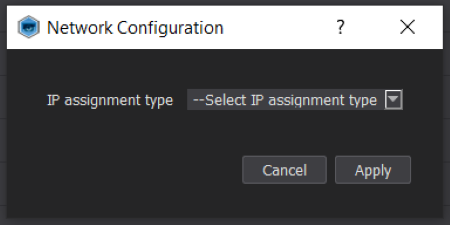
The three different IP assignment types are reflected in the PhoXi Control setup. The configuration can be done by clicking the Configure button in the lower part of the Network Discovery window. You can select between DHCP and Static IP. The device restarts after every change in network configuration.
Choosing Static IP changes the window where, IP address, Gateway, Subnet mask, and DNS can be set up. Please note that setting an invalid IP address will make the device undiscoverable on the network, so make sure the IP address is valid and not outside the subnet you are on.

By default, the devices use DHCP for IP assignment. On networks with no DHCP, the IP will be assigned by Zeroconf.
Using Zeroconf technology for service discovery does not rely on any specific PhoXi Control configuration - the IP assignment type can be left blank or set to DHCP. After the device is connected to a network without a DHCP server, it should already be available in PhoXi Control. The only requirement for Zeroconf to work correctly is to have Avahi installed on Linux systems and Bonjour service on Windows systems.
If a device is moved from a network with a static IP address assignment to a network with a dynamic IP address assignment, before the device is disconnected, its IP assignment type should be changed to DHCP.
Checking Computer Network Configuration
Note that the IPv4 addresses used in the following pictures are just for illustrative purposes and may not work on your network.
Windows |
|
Automatic DHCP method |
Static IP |
|
|
|
|


Ubuntu |
|
Automatic DHCP method |
Static IP |
|
|
|
|


Network Environment Variable for IPv4 Preference
If it is possible, the device always establishes a connection via IPv6. To prefer an IPv4 connection before an IPv6 connection, set the environment variable:
PHO_PREFER_IPV4 == ON
Adding device via Address

A device can be added using its IP address in the Menu -> Add device via Address which displays the following dialog. A device added in such a way will carry a different icon and user-defined name DirectConnection-<User-defined>

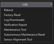
Utils
The Utils button (previously Maintain) is located at the very right-bottom corner of the Network Discovery tab and offers a list of functions to control the device. A device must be selected to use this option.
Warning
Rebooting device disconnects anyone currently using the device.
Reboot
Reboot restarts the device.
Factory Reset
Factory Reset restores the device to its factory state.
Note
This will remove all user profiles and applied calibration patches.
Log Downloader
The Log downloader allows the user to download logs from the device directly from the PhoXi Control GUI.
Verification Report
View the Verification report for the selected device. This report confirms the successful completion of the final quality check.
Maintenance Tool
Maintenance tool is a Photoneo software for validation of Photoneo 3D Sensors based on the acquisition of a marker pattern. It is used to verify device calibration and adjust it if necessary. Find out more in the Maintenance Tool section.
Autonomous Maintenance Reset
Autonomous Maintenance Reset restores the device’s calibration to its factory state without impacting the user profiles or other settings.
Sensor Alignment Tool
This tool is a command-line application designed for the spatial alignment of multiple Photoneo 3D Sensors. It calculates and applies the spatial transformations to align two or more scanners into a single, shared coordinate system. For more detailed information, see Sensor Alignment Tool.
Device Window
The Device Window is the main screen used to control the device. It is divided into 3 sections:
Main controls (red)
Device settings pane (green)
Visualisation pane (purple)
Status bar (yellow)

Main Controls
This pane provides the basic functions and advanced tools for triggering and saving scans and for safe disconnection from the device.
Acquisition Modes - Triggering Scan

Single scan mode (default)
The device waits for the trigger command to capture a 3D scan.
Use the Trigger / Set and Trigger / Trigger Diagnostics button
The Set and Trigger button automatically temporarily saves changes made in the Device Settings or Structure tabs and triggers a scan.
Trigger Diagnostics takes a special scan that contains the most information, and can take longer to compute. See Diagnostic scan chapter for more information.
Trigger, Set and Trigger and Trigger Diagnostics are 3 settings for the same button. Settings are changed through the dropdown menu accessible through the small arrow next to the button.
Trigger Auto-Maintain is a dedicated button for Autonomous Maintenance. This feature is available only on MotionCam-3D devices shipped after the 26th of May 2025 and on PhoXi 3D Scanner Gen3.
Free run mode
The device performs consecutive scans at maximum speed (if not slowed down by the Maximum FPS setting).
To turn the free run mode on or off, use the button Free run.
When the device is in Free-run mode, you can pause and restart the acquisition with the Pause / Start button.
Photoneo 3D Sensors can also use a hardware trigger to acquire scans. In hardware trigger mode, the scan is triggered by a signal change on a specific GPIO pin. More information can be found in the section Hardware trigger.
You may prevent the device from taking a scan by using the Pause button at any time. Using this function is more intuitive in the API, where a secondary application may prevent the first application from triggering the scan.
Tip
Once the window is open, hit F5 or the Trigger button to trigger a scan.
Assistant
The Settings Assistant guides you through a step-by-step process to find the ideal settings for the specific scene.
Tip
For a step-by-step visual demonstration, you can watch our video tutorial on how to use this feature here.
You can pick one or multiple dimensions:
1 - Exposure - Adapts to the light conditions, environment, and scanning distance
2 - Material & Object Type - Adapts to object material by adjusting core scanning methods
3 - Exposure Fine Tuning - Refines the light settings around the best option from previous step
4 - Enhance & Clean up - Perfects the scan by increasing the level of detail and decreasing noise
Once you select each of these dimensions, the Settings Assistant initiates an automated process to explore the best parameters within each chosen category.
For each dimension you pick, the Assistant performs the following actions:
Step |
Action |
Outcome |
|
The Assistant automatically captures several frames, each using a different scanning profile relevant to the selected dimension (e.g., 9 different exposure settings). |
A gallery of several distinct scans is generated for your review. |
|
It analyzes each of the frames, reporting the scanning time and the number of points in the resulting point cloud. |
You receive comparable data to help you evaluate the trade-offs between speed and number of points for each profile. |
|
Based on its analysis, the Assistant highlights one of the profiles as the recommended best choice. |
You get a suggestion, but the final decision remains in your hands. |
|
Based on your final selection, a new, optimized custom profile can be created and saved. |
This delivers a “plug-and-play” experience, providing you with the best possible scanning parameters in just a few minutes. |
This systematic process ensures you can quickly fine-tune your scanning setup for optimal quality and performance, tailored precisely to your object and environment.
Settings Assistant guide
- Use the Assistant button to initialize the Settings Assistant tool.
 Settings Assistant for
<Device SN>will open. The following windows contains two tabs Scan generation and Best scan selection which are switched automatically throughout the process.
- Choose one of 4 dimensions (1 - Exposure, 2 - Material & Object Type, 3 - Exposure Fine Tuning, 4 - Enhance & Clean up) or use the default order as represented by the numbers enumerating each of the dimensions starting with the 1 - Exposure (recommended).

- Hit the Generate scans button. The tool will automatically capture several scans with different parameters according to the chosen dimension.

- Afterwards, a new file camera named
<Device SN>-<dimension>(in our casePHA-125-Exposure) will be connected.
- The Settings Assistant automatically switches to the Best scan selection tab, where you can compare individual scans. Each scan is represented by a button that displays its scanning time and the number of points in the point cloud (taking the selected resolution into account). Scans are sorted based on the total scanning time from shortest to longest. One scan is always designated as the reference scan, and another is marked as Suggested based on a combined rank of the scanning time and the amount of point cloud data it contains. You can cycle through the scans by using the buttons, the blue arrows, or the ← and → arrow keys on your keyboard.
Tip
Hovering over each scan’s button will display its Acquisition, Computation, and Transfer times, as well as any adjusted parameters.

- Select the best scan. In the image below, for example, the first scan was suggested but the user chooses the 6th scan.

- Provided you have the best scan selected, you can use the Save into profile button to save the current parameters (optional at this point). If you are satisfied with the result, you can opt to exit the Settings Assistant by selecting the Exit button. To continue optimizing the scanning parameters, use the Optimize further button which takes you back to the Scan generation tab.
- Once you are back in the Scan generation tab, you can repeat the same process by selecting another dimension.

- You can exit the Settings Assistant using the Exit button which closes all the related windows and file cameras. You will be prompted to either save all the generated scans or exit without saving the scans.Make sure you saved your profile before exiting the Settings Assistant or otherwise the parameters will be lost.

- To view the created profiles, refer to Scanning Profiles section.
Saving 3D Scans
PhoXi Control allows you to save scans both manually and automatically. The automatic saving mode is called recording.
The output can contain:
Point cloud: an organized set of 3D points.
Normals: for each captured 3D point, the normal vector expresses the orientation of the captured surface.
Depth map: the depth data for each pixel.
Texture: grayscale intensity or RGB values for each 3D point.
ColorCameraImage: 2D RGB texture captured by the color camera unit in MotionCam-3D Color and PhoXi 3D Scanner Gen3
Confidence data: the data expressing the estimated noise of the acquired point.
Split RGB Channels: control over production of channel files for Texture and ColorCameraImage.
Information about the device, such as the ID number or calibration data of the image sensor
Information about the 3D scan, e.g. duration, scanning parameters, coordinate system
All these data can be stored only in the native Photoneo RAW formats ( *.praw or *.pmraw). They can be opened later in PhoXi Control as a File Camera and converted to any other supported file format.
Other scan formats (PLY, PTX, TIF) are capable of storing only partial information, usually only point cloud, normals, and texture. The saving options dialog enables the user to choose from output structures saved in each file format.
List of Supported Formats
Photoneo RAW data format (*.praw)
MotionCam-3D RAW data format (*.pmraw)
Stanford’s PLY (*.ply)
Including an option to save PLY file with optional MESH
Leica’s PTX (*.ptx)
Text file (*.txt)
Raw images in tif (*.tif)
For each format, you can choose which data to store (point cloud, normals, texture…). For further information, see the Saving Options section below.
Saving Single Scan Manually
After triggering a scan, use the Save button to open the saving dialog. Choose one of the supported formats and saving directory.

Saving Scans Automatically - Recording
Firstly, use the saving options dialog to define the destination and file formats in which the acquired scan should be stored. Using *.txt format to save data during recording is not recommended. Afterwards click the Record button to start or stop automatic recording.
When recording is used in free run mode, the disk writing speed may limit the number of stored frames and some frames might be skipped and not stored. This usually happens when multiple file formats are being saved at once or when compression is used to save *.praw files. If this occurs, the status bar in PhoXi Control displays the message “Scans cannot be saved, they are generated faster than the computer can process them. Consider changing saving options.”.
Recording Options
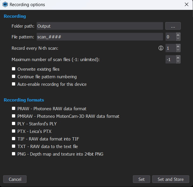
Use the button Recording Options to configure how the 3D scans and corresponding data are saved.
The Folder path and File pattern fields are used by automatic recording. The folder path defines the destination where the scans will be saved. The file pattern defines the name of the files, hash signs will be replaced by a counter starting at the defined value. The image on the right depicts the settings that will save the scan with the name scan_0000. Other possible tags in the File patterns include {file_index}, {device_id}, {frame_id}, {timestamp}, {date_time}, {frame_start_timestamp}, and {frame_start_date_time}. These tags enable dynamic insertion of session-specific variables into filenames. Users can also define the frequency of saved scans by changing the N parameter. Additionally, the number of scans can be limited by the Maximum number of scans parameter. Use the checkboxes on the left to select all the formats in which the scan should be saved during automatic recording. Use the Options buttons on the right to define which data should be saved when using the selected file format.
Tip
Any scan in a *.praw / *.pmraw format can be converted into any other format by loading it into PhoXi Control and choosing a different file format in the saving dialog.
Specifics of File Formats
An Explanation of the Confidence map can be found in the 2D Image Tabs section
Using a text file to save data may result in longer saving time, depending on the speed of your SSD or HDD. The same is true when the binary format is not used in the PLY format.
TIF file is one-dimensional, therefore it creates multiple files for each stored component.
Understanding Scanner Outputs - Topology of the 3D Scan
The point cloud acquired by PhoXi 3D Scanners is topologically organized according to the image sensor. An image from the image sensor is called texture. There is one computed 3D point for each pixel in the texture. If any point from the scene is not illuminated by projection (usually because of shadows) the corresponding pixel has no 3D value (its coordinates are [0, 0, 0]) and is called a “zero 3D point”.
For example, the pixel at position [x= 2010, y =350] in the texture is the (2064*350 + 2010) = 724410-th point in the point cloud.
PhoXi Control also allows unorganized point clouds to be saved. In unorganized point clouds, the “zero 3D points” are omitted and not saved; therefore, the topology is lost. If you have an unorganized point cloud and would like to restore its organization, you will need to iterate over the point cloud and find a corresponding pixel in the depth map by comparing the Z value.
Understanding MotionCam-3D Output - Topology of the 3D Scan
On MotionCam-3D the relationship between the number of pixels on the image sensor and the number of points in the point cloud is not 1:1. The ratio depends on the Sampling and Output Topologies.
Diagnostic recording
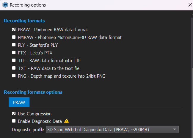
This tool serves to save scans for diagnostic purposes independently from the client application. The setup allows choosing how often and where the scans are saved, and what information is contained within them. Open the Recording Options and select PRAW format. Then scroll down and you can see the possibility of recording Diagnostic Data.

When the maximum log file size is surpassed, deletion of *.praw files will commence, beginning with the oldest *.praw file. This tool can save:
3D scans
3D scans with diagnostic data
3D scans with full diagnostic data (default, recommended)
2D outputs
2D outputs with diagnostic data
Note
Different diagnostic profiles have different performance impact, resulting in higher processing or transfer time.
Diagnostic Scan

The user can also trigger a single diagnostic scan. Click on the drop-down arrow next to Trigger and select Trigger Diagnostic.
This scan saves the most amount of information. It can take longer to compute and the user is notified about the diagnostic frame by a yellow taskbar.
Note
Diagnostic scan should be saved in PRAW format.
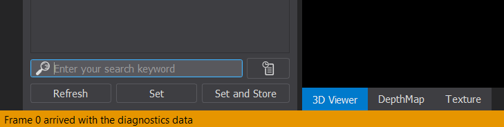
After saving the scan with the Save button, it can be sent to Photoneo Support.
Tools
Test Speed
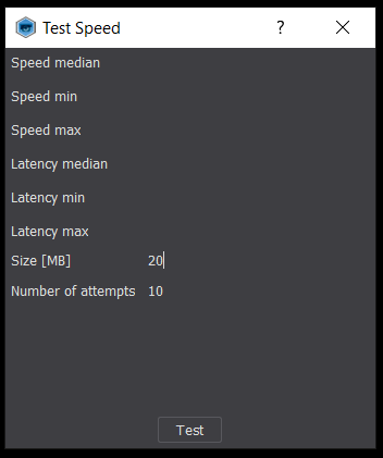
This tool can be used to measure the transfer speed between the device and the computer running PhoXi Control. Use the default settings for Size [MB] and Number of attempts in case you don’t suspect any connection issue.
If you suspect there is a slow connection speed, change the parameters Size [MB] and Number of attempts to lower values.
The result of the test is shown as Speed and Latency with their minimal, maximal, and median values. On 1 Gbps networks, the expected speed should be around 100 MB/s with a latency below 6 ms.
Low speeds significantly prolong the overall scanning time. Check if the network cables are of a Cat5e category or higher. Lower-category cables have a speed of around 10 MB/s.
Tip
Besides the ability to use the Test Speed, IPv4, and IPv6 address rows in the Network Discovery tab contain dynamic interface labels. The labels dynamically change color: red for non-routable addresses, orange for sub-1Gbps interface speed, and blue for normal operation (1Gbps and higher).
View
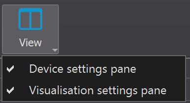
Toggle the visibility of GUI components:
Device settings pane:
The pane on the left side contains device settings.
Visualisation settings pane:
The pane on the right-hand side contains options to change the visualization of the point cloud.
Device Logout
Clicking the Logout button disconnects PhoXi Control from the currently selected device. Closing PhoXi Control without disconnecting from the device may produce a warning when the next connection is established

Select Frame

This setting is only available for viewing File Cameras. It opens a new window where you can select the index of the *.praw or a specific scan in a *.pmraw file that will be displayed after the next scan is triggered. The file is selected based on the order of the files in the directory (index starts with 0).
Device Settings Pane

Contains the scanning profiles selector and scanning parameters (tab Settings).
Allows control of the output data received from the device (tab Structure).
The set of scanning parameters and profiles depends on the firmware version of your device. This User Manual is based on FW version 1.16.5.
Scanning Profiles

Scanning profiles allow users to easily change multiple scanning parameters at once. There are several profiles pre-configured with different scanning parameters for different uses. Factory profiles are not editable, and cannot be deleted or renamed, however, it is possible to clone them and edit the cloned profile. A different set of factory profiles is available for MotionCam-3D and PhoXi 3D Scanner. It is also possible to define custom profiles.
Use the cog  button to enter the advanced configuration.
Select - switch to the chosen profile.
Save current settings - save your current settings in a new profile.
Duplicate - create a new duplicate profile from your selected profile.
Delete - delete user-created profile.
Rename - rename the user-created profile.
Mark as startup profile - the device will be started with this user profile.
Reset to factory settings - resets settings to factory default.
Export to GigEV UserSet - Export a selected user profile as a GigEV UserSet
Export - save a user profile into the *.phop file.
Export all - saves all user profiles into a *.phop file.
Import - imports a user profile from a *.phop file.
Using a Custom Profile
Use the button
and create a new profile from the existing one, which is closest to your use case. You might want to mark it as a startup profile as well.Modify the desired parameters to your needs.
Use the Set and Store button below to store the settings in your custom-made profile permanently.
Scanning Parameters
The set of scanning parameters available depends on the version of the firmware installed on the device. This manual is based on firmware version 1.16.5.
The scanning process consists of three phases: capturing (or acquisition), processing (computation), and transfer.
Scanning parameters are divided into several groups. These groups differ depending on the device as shown below.
PhoXi 3D Scanner

General Settings - settings that control the operating mode of PhoXi 3D Scanner
Capturing Settings - these options change exposure times and methods of projecting light patterns.
Color Settings* - settings for 2D RGB camera unit.
Processing Settings - these options affect the computation of the point cloud and allow the setting of filtering criteria such as the region of interest.
Coordinate Settings - defines the coordinate space for the point cloud.
*only with the PhoXi 3D Scanner Gen3
MotionCam-3D

General Settings - settings that control the operating mode of MotionCam-3D (camera or scanner mode)
Color Settings* - settings for 2D RGB camera unit
Camera Mode - settings for acquisition in camera mode
Scanner Mode - settings for acquisition in scanner mode
Processing Settings - point cloud computation and filtering (ROI)
Coordinate Settings - define the coordinate space for the point cloud
*only with the MotionCam-3D Color
The total scanning time is the sum of the time required for acquisition (defined by capturing settings), computation (defined by processing settings) and transfer (defined by Output structure).
The use of scanning parameters is described in the Scanning Guide - Parameters at the end of this User Manual.
Controls
Search box (Ctrl+F)
Search setting by name. Search box offers auto-suggestions based on all available settings for the connected device.
Set button (Ctrl+S)
Sets scanning parameters for the current session only. Settings are discarded after the device is disconnected.
Set and store button (Ctrl+Shift+S)
Stores scanning parameters permanently to the device’s memory (applies to the current profile).
Refresh button (Ctrl+R)
Retrieves current settings for the selected profile from the device’s memory.
Structure

Output structure lets you choose what kind of data will be retrieved from the device. Any changes to the output structure will affect the transfer stage. The read-out time can be sped up by selecting only the data which you need for your application.
PointCloud |
The point cloud is a set of measured 3D points. Each 3D point has the coordinates X, Y, and Z in the point cloud coordinate space (see Coordinate settings). The point cloud has a topology that depends on the device in use. On PhoXi 3D Scanners each point in the point cloud corresponds to the pixel on the image sensor. On MotionCam-3D the points are organized in superpixel topology - 2 or 4 3D points per one superpixel in irregular patterns or can be interpolated into a grid topology that resembles that of the scanner. Unmeasured points (pixels) caused by shadows are given the default coordinates [0, 0, 0]. Based on the saving options, these unmeasured points might or might not be saved. The point cloud can be examined in the 3D Viewer tab. |
NormalMap |
The normal vector for each 3D point can also be calculated. The normal vector is perpendicular to the area surrounding the point (see Normal estimation radius). Normals can be inspected in the 3D Viewer tab after selecting the display parameter in the right pane. |
DepthMap |
The “depth” of a point is the absolute 3D distance from the image sensor to the measured point (the ray of light that hits the surface of the object). The DepthMap is, therefore, always in the camera coordinate system and corresponds to the Z coordinate value in the point cloud. Note: Even when you change the point cloud coordinate space, the DepthMap always shows the distance (depth) in the camera coordinate system. |
Texture |
Texture is the 2D photo of the scene. The texture is either in grayscale (in the red spectrum - the source of the illumination is either LED diode or laser projection) or Color captured by the RGB camera unit on MotionCam-3D Color and PhoXi 3D Scanner Gen3 (source of the illumination is either ambient light or internal white LED). The texture is also used to color the 3D point cloud. |
ConfidenceMap |
For each measured 3D point, the “confidence” value expresses certainty about the accuracy of the point measurements. For example, a confidence value of 0.12 means that the estimated error for a point measurement is 0.12 mm. This value is based on a heuristic method that considers the light conditions for each pixel. |
EventMap |
EventMap is a 2D output available only on MotionCam-3D. For each measured point, it shows the time when it was captured. The time is in milliseconds and is measured from the beginning of exposure - each point can have a value from 0 up to the total duration of exposure - i.e. 10 ms. |
ColorCameraImage |
This output is only accessible on the MotionCam-3D Color and PhoXi 3D Scanner Gen3. When set to true, it outputs an image from the RGB camera unit in the resolution specified in the Color Settings in the settings tab. |
Note
Adjusting the resolution of the ColorCameraImage can affect the performance of the MotionCam-3D Color and PhoXi 3D Sensor Gen3.
Search history


 icon situated next to the search bar at the bottom of the Device Settings Pane allows the user to open the Search history window. This window contains the recent search inputs and can be very helpful when reusing a specific parameter repeatedly.
In the bottom right corner of the window, 3 buttons are available:
 - Dock the Search history window
 - Delete selected history (DEL key)
 - Clear search history
Docking the Search history window will result in the search history being available under the search bar.
Visualization pane
This pane displays the output from the device in various views. After the Device window is opened, hit F5 or press the Trigger scan button in the main controls to trigger the scan. The output is provided as a 3D point cloud (3D Viewer tab) and a set of corresponding data as 2D images (all other tabs). The view can be switched using the tabs at the bottom. Each view has its own display settings on the right. These settings do not change the data themselves, just their visualization.

3D Viewer
Use this tab to inspect the point cloud and obtain a general overview of the scanned scene.
OpenGL support
In case that OpenGL does not have the required version necessary to visualize 3D point cloud, the following error message will appear. It provides additional information about the current setup for your computer and notifies you that the given version of OpenGL does not meet the requirements to showcase 3D point cloud.
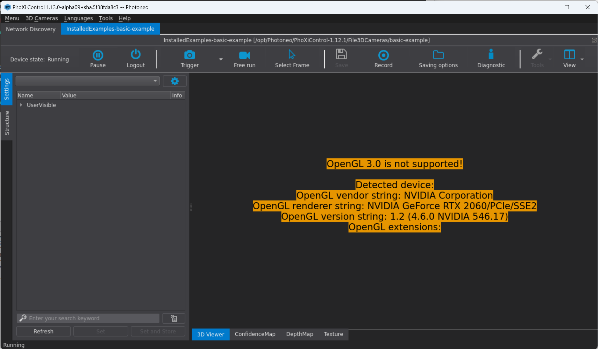
3D Viewer can be disabled. Refer to Disabling GUI or 3D Viewer.
Changing the Visualisation
Reset view |
Resets the camera to the default position. |
Screenshot |
Allows the user to save a *.png screenshot of the 3D Viewer window. |
Intensity |
Select the data source for coloring the point cloud:
|
Visualization settings |
Adjusting the brightness and contrast of the scene.
|
Show normals as ticks |
This checkbox allows the rendering of normal vectors for selected 3D points. The selection of 3D points can be adjusted using the Stride setting and the length of the vectors by the Length setting. |
Coordinates |
Displaying the coordinate system:
|

*If after checking the Axis you do not see anything different, try zooming out in your 3D point cloud. Because the coordinate system origin is at the camera, you may not see the arrows representing axes if your current camera position aligns.
Transformation matrix
Transformation matrix |
Show the transformation matrix from “Point Cloud Space” to the currently chosen “Camera space” (or vice versa). Point Cloud Space is a general term used for the currently chosen Coordinate Space (CameraSpace, MarkerSpace, RobotSpace, CustomSpace or PrimaryCameraSpace). See the Coordinate settings section to understand the essential terms (ColorCamera, PrimaryCamera, CameraSpace, Marker space). |
Intrinsic Parameters
The Intrinsic parameters section within the Visualization pane displays the effective Camera Matrix and Distortion Coefficients based on the currently selected CameraSpace. This feature allows users to easily view and copy these critical calibration values directly from the GUI interface.


Frame Information
Frame information section |
Shows information about the current frame, such as
|
Note
The displayed frame information also depends on the FW version of the device. Above presented frame information is present in FW 1.16.
Given information can also be edited by the user. Right-click on any of the information and click on the Content editor. This then opens a new window called Frame info editor.
After hitting Apply the information is updated in the Visualization pane.
3D Viewer Controls
Left mouse button drag |
Rotates the point cloud around the selected point of focus. By default, the selected point of focus is the camera position. |
Mouse wheel or Vertical right mouse button drag or Keys: [ ] |
Zooms in/out. |
Mouse wheel drag or Hold SHIFT + left mouse drag |
Moves the point cloud. |
Hold CTRL + left mouse drag |
Tilts the point cloud. |
F |
Sets the point of focus to the point under the mouse cursor. This is the point around which the scene is rotated. |
R |
Resets the view to default. Used to center the view on the point cloud. |
Key: + |
Increases the size of the points. |
Key: - |
Decreases the size of the points. |
File Camera Controls
Left arrow |
Previous frame |
Right arrow |
Next frame |
Shift + left arrow |
Go 10 frames back |
Shift + right arrow |
Go 10 frames forward |
Home |
Go to the first frame of the file camera |
End |
Go to the last frame of the file camera |
2D Image Tabs
Confidence Map
This tab displays the predicted error of depth measurement for each pixel (corresponding 3D point). Darker areas on this map show parts of the scene that have been scanned with lower error rates, while brighter areas show parts of the scene where errors may have occurred, suggesting that these sections of the scene may be problematic. The Confidence Map serves as a tool for estimating inaccuracy in millimeters. It can be used to find places where the inaccuracy is high and then trim them away using the Max Inaccuracy (mm) setting.
To see the confidence map, it is necessary to turn on the Confidence Map checkbox in the output structure and then trigger a new scan. Set the Maximum value threshold in the right pane to a reasonably small number, e.g. 0.5. Then hover the mouse cursor over the image to see the value of the specific pixel (its corresponding 3D point).

Depth Map
This view shows the scene as a gray-scaled image in which the intensity of every pixel represents the distance of the measured point from the camera. The depth value of the pixel under the cursor is shown on the right side pane as the current pixel value. The image can be made more readable by adjusting the settings on the right side of the window, as explained below. This view can also be used to measure the distance between 3D points by dragging a line between corresponding pixels with the right mouse button.

Texture
The texture is a 2D photo of the scene. Intensities from the texture are used to color the point cloud.

Event Map
Event Map displays time information about when each 3D point was acquired. The measurement starts and ends together with the acquisition of 3D data which is achieved by sweeping a laser line over the object and modulating pixels in the camera sensor. Each point in EventMap can only have values ranging from 0 to Exposure time ( ie 0 - 10 ms).
The time information is useful for applications where movement plays a role. MotionCam-3D can scan objects moving at high speeds, however, depending on the speed and direction of the movement, the resulting point cloud can be distorted. Combining the information from the EventMap with information about the speed and direction of the object is necessary to reconstruct the point cloud.

ColorCameraImage
After setting ColorCameraImage to true, a Color 2D image tab will appear at the bottom of the Visualisation pane. It is the native RGB image from the RGB camera unit in the MotionCam-3D Color and PhoXi 3D Scanner Gen3. Its resolution can be altered in Color Settings.
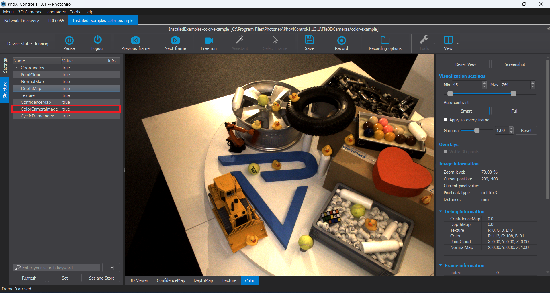
2D Image Tabs Visualisation Controls
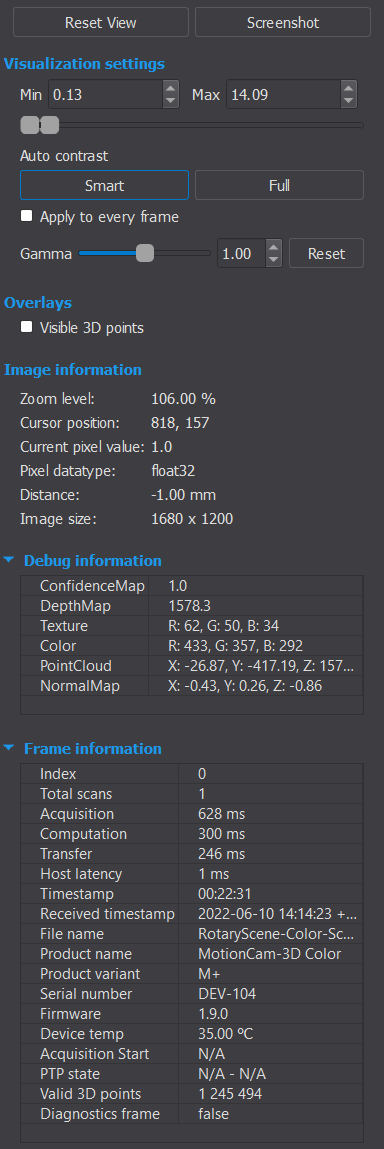
The top part of the 2D image tabs visualization controls and the Frame Information are the same as in the 3D viewer visualization controls.
Overlays
Visible 3D points |
Creates an overlay of visible 3D points on the currently opened 2D image tab |
Image Information
Zoom level |
Current zoom level of the image. |
Cursor position |
Position of the pixel under the cursor. |
Current pixel value |
Value of the pixel under the cursor. |
Pixel datatype |
Represents the data type of the image. |
Distance |
The distance between two points. You can measure the distance between two points by dragging a line between them with the right mouse button. The computation takes into consideration the position of the points in 3D space. |
Image size |
Image size in pixels |
Debug Information
When hovering over a specific pixel with a mouse cursor, the debug information pane displays values of all of the available output maps for the current pixel.
Controls
Button: Set default view |
Resets the image position and zoom to default values. |
Button: Restore default settings |
Restores the default settings for Intensity settings. |
Left mouse button drag |
Tilts the scene. |
Mouse wheel |
Zooms in/out. |
Right mouse button drag |
Draws a line between two pixels and computes the distance between the two corresponding 3D points. |
Measuring tool
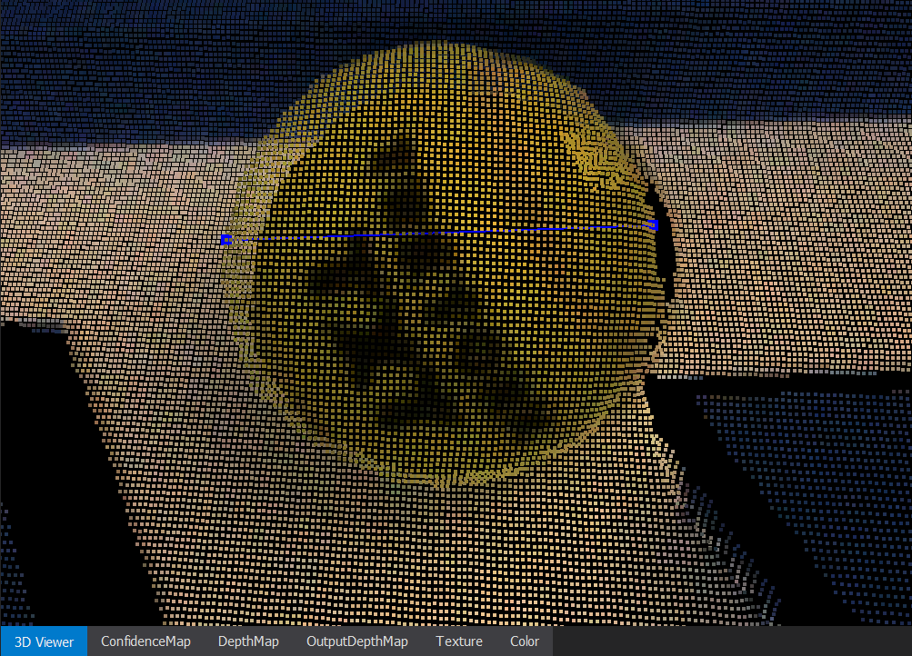
The Measuring tool allows you to quickly measure the distance between two selected points. Using Right mouse button drag, you can draw a line between two pixels, and the tool will compute the distance between the corresponding 3D points. Once placed, the points can be repositioned by clicking and dragging them with the left mouse button to a desired location, as long as it corresponds to a valid 3D point.

After selecting the two points for distance calculation, you can move them around in all 2D Image Tabs, except the 3D Viewer tab. The 3D Viewer tab allows you to visualize the placement of the points in XYZ, but adjustments must be made in one of the 2D Image Tabs.
Undock Device Tabs
This feature allows the user to observe more device windows while working with multiple devices and/or file cameras by opening more undocked tabs side by side.

This feature allows the user to undock a device tab from the main PhoXi Control base tab and position it anywhere on the screen. In the case shown below, all 4 tabs can be moved separately and the user can adjust both the width and height of the window.

Example of 4 simultaneously observed undocked tabs.
Additionally, the user can also dock the individual tabs in the PhoXi Control base tab and use it in a split-screen view. In another case shown below, all 3 tabs are docked and the user can adjust the width of the individual windows.

Example of 3-way split-view within PhoXi Control
Status bar
In the lower part of the Device Window, you can find the Status bar. Status bar is the communication tool of PhoXi Control, where all the info messages, warning messages and error messages will be shown.

Messages have a pre-determined structure:
Type of message
Info - no special color change, no need to change any settings or anything in the scene you are scanning.
Warning - yellow status bar. This might be the warning that you have diagnostic data turned on, which may not be desirable, or that the device is paused while you are trying to trigger a scan. Therefore you may have to change settings.
Error - red status bar. You need to change settings or something in the scene to continue scanning correctly.
(code of message) - code of the message. It is written in brackets.
Message text - Description of the problem.
Here are the most important or most common messages you can see on your Status bar:
Info |
Scan triggered for frame [frame number] |
Info |
Frame [frame number] arrived |
Info |
Scan saved successfully |
Info |
Settings set successfully |
Warning |
Unpause the device before triggering a scan. |
Warning |
Unpause the device to record. |
Warning |
Frame [frame number] arrived with the diagnostic data |
Warning |
Saving - with the diagnostic data… |
Warning |
Scan saved successfully - with the diagnostic data |
Warning |
Scans cannot be saved, they are generated faster than the computer can process them. Consider changing recording options. |
Error |
Failed to set settings! |
Error |
Error while saving scan for frame: [frame number]! |
Error |
Image corrupted! |
Error |
Marker pattern was not recognized (3D-Based)! |
Tools for Infield Maintenance
Photoneo 3D Sensors offer a variety of tools for infield maintenance.
-
Supported on MotionCam-3D, MotionCam-3D Color, PhoXi 3D Scanner, Alpha 3D Scanner devices
Marker pattern required
Command line application executable via PhoXi Control GUI and API
-
Supported on MotionCam-3D, MotionCam-3D Color, PhoXi 3D Scanner, Alpha 3D Scanner devices (shipped after 05-26-2025)
4 or more Marker dots required
GUI, API
-
Supported on MotionCam-3D Color (shipped after 05-26-2025) and PhoXi 3D Scanner Gen3
No markers or marker board required
GUI, API, GigE
Using one or combination of the tools is recommended:
During system setup, before starting operations
If the device experienced extensive vibration or physical shock (transport, robot collision)
After major environmental changes, like a relocation or temperature/humidity fluctuation
As a part of a precision-focused workflow, where you might want to run a quick check regularly (recommended once or twice a year, or during general system maintenance sessions)
Maintenance Tool
Maintenance tool is a Photoneo software for validation of Photoneo 3D Sensors based on the acquisition of a marker pattern. It is used to verify device calibration and adjust it if necessary.
Prerequisites
Maintenance tool requires a marker pattern (A2, A3, A4, A5, S30) printed on a flat, high-quality surface (e.g. float, tempered and heat strengthened glass, PCB board, Komatex, Metal board - Aluminium/steel, etc.). The default scaling (100%) of the marker pattern is recommended. Using incorrectly scaled marker patterns may lead to inconclusive or incorrect calibration patches.
The device should be running for at least 45 minutes before maintenance.
Using Maintenance Tool
In the Network Discovery window, select the desired camera (do not connect) and click Utils (previously Maintain) in the lower right corner. Then, choose Maintenance Tool to automatically connect and open the Device Window and Maintenance tool console.
The Autonomous Maintenance Reset restores the device’s calibration to its factory state without impacting the user profiles or other settings.
The marker pattern should be statically placed in front of the device (for example not held in hand). Place the pattern in optimal focus distance (See Marker Pattern chapter to see which marker pattern size is recommended for your camera, as well as ideal distance for the given marker pattern).
Note
It is recommended to change the user profile to DEFAULT and use command adjustPower, to automatically set the optimal scanning parameters.
To trigger a scan, either use the command trigger, or press t, and then ENTER key on your keyboard in the console after connecting to the camera. Do not trigger a scan in Device Window - information from that scan will not be sent to the Maintenance tool.
It is necessary to cover as much of Field of View (FOV) as possible. Otherwise it will not be possible to continue maintenance of the device.

The image above shows the most optimal placement of the marker pattern for the scans. However, the exact placement or the number of layers depends on the size of the marker pattern chosen by the user, as it is necessary to cover as much of the Field of View (FOV) as possible. If the marker pattern is larger, fewer scans are necessary to cover the FOV.
Starting with PhoXi Control 1.17.0, the Maintenance Tool supports multiple identical validation targets present in the scene at the same time. You can place several copies of the same marker pattern into the scanner’s field of view. The tool will automatically recognize and use all the recognized patterns. This helps to reduce the number of frames needed. Support for multiple identical patterns is enabled by default.
After the acquisition is done, enter the command analyze. The analysis results in one of the following options:
Calibration patch is available. Please continue with uploading the patch (via command
patch)Calibration patch is available. It is strongly recommended to continue with uploading the patch (via command
patch)The MaintenanceTool is unable to fix the calibration, please contact the support.
Scans of pattern are not well distributed and do not cover scanning area homogeneously. Please, add scan(s) of the validation target to improve the scanning volume coverage.
Scans of the pattern do not sufficiently cover the projection range. Please, add scan(s) of the validation target to improve the projection range coverage.
If the marker pattern is too small for the size of the device, during the command analyze it will show a histogram of coverage.
After patching the calibration, exit the Maintenance tool using the command exit. If you also wish to disconnect from the camera, use the command exit disconnect.
If it is necessary, it is possible to revert any calibration of the camera back to its original factory settings using the command restore.
Maintenance tool is also available to use through API.
Marker Dots

Marker Dot Correction is a Photoneo feature used to maintain a point cloud from a 3D Sensor at a “fixed position”, with respect to marker dots permanently installed in the scene.
Prerequisites
Photoneo 3D Sensor (shipped after 05-26-2025) running Firmware 1.16 or higher
Marker dots, which are purchased from Photoneo. Marker dots come in two sizes (mm):
65 x 65 for Scanners of sizes S, S+, M, M+ and L
140 x 140 for Scanners of sizes L, L+, and XL
The device should be running for at least 45 minutes before maintenance.
Marker Dot Correction Process

4 or more Marker dots need to be rigidly placed in the FoV of the Photoneo 3D Sensor according to the Correct Marker Dot Placement and Conditions for Recognition.
Marker Dot Correction can be controlled in the GUI (Processing Settings → Marker Dot Correction) or using the PhoXi API as demonstrated in the MarkerDotCorrectionExample.cpp
The Reference Recording mode saves the position of the marker dots. Reference Recording is stored even after disconnecting from the device or turning the device off. Only factory reset or failed attempt to record a new Reference Recording erases the reference.
After the device contains the reference recording, automatic mode can be used which automatically recognizes the marker dots in every scan and performs an adjustment so the point cloud remains fixed at the learned position. This operation is performed by the FW of the device. (Computation time: <150ms)
If the Marker Dots are not visible the last calculated correction is applied.
If the correction application was a success, the result is stored in the scan’s metadata. If the correction exceeds acceptable configurable thresholds, the device will send out an alert. Use the Maintenance Tool to verify the performance of the device. The Maintenance Tool patch invalidates the last Reference Recording.
For diagnostic purposes, a small log is generated and stored on the device. The logs are being overwritten and can be retrieved via the LogDownloader utility and sent to Photoneo for analysis.
For time-sensitive applications, switching between active and passive mode is recommended (for example, switching to Active mode for one scan in every 1000 scans in Passive mode). The passive mode does not check the positions of the marker dots in the scene. It only applies the last known correction.
The change between the initially recorded and recognized position of the marker dots is defined in millimeters and exceeding a definable threshold triggers a warning. See more in the Marker Dot Shift Threshold.
Operation Modes
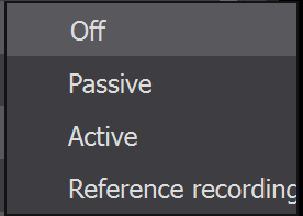
Marker Dot Correction has 4 Operation modes:
Off - the Marker Dot Correction functionality is not used
Passive - apply the last calculated metric and coordinate correction
Active - capture marker dots, calculate and apply metric and coordinate correction
Reference Recording - capture reference (this mode should be used only once, at the beginning of the correction)
Marker Dot Shift Threshold
Marker Dot Correction has Max Marker Shift (<double>) - maximal permitted pixel shift of the markers (with regards to Reference Recording). This prevents the correction application in case of dots being moved by accident. It is not recommended to raise this value above 25 pixels.
Correct Marker Dot Placement and Conditions for Recognition

The Marker Dots can be shown in the scene by placing them in the scene or mounting them. Each Dot has 4 mounting holes in each of the corners.
The Minimum number of dots in the scene is 4.
The minimal distance between the leftmost and rightmost Dot should be at least half of the calibration volume (half of the angular range covered by the projection)
The Marker Dots should not be clustered in one place. PhoXi Control will warn the user about the incorrect placement of the Marker Dots.
Marker Dots help the device to calibrate its position during the process of recording scans. The marker dots should not be placed in a collinear position - in a single line in space (the distance from the device [depth] is not considered when checking the collinearity of the Marker Dots). The collinearity of the dots is checked during Active mode, not during Reference Recording.
A new Reference Recording has to be acquired in case of a change (e.g. position of the device, dots have been repositioned)

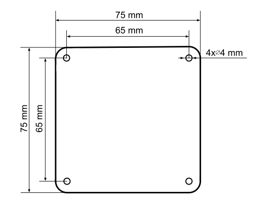
Marker Dots Correction can be used via PhoXi API using the MarkerDotCorrectionExample.cpp. (See the API Examples section).
Autonomous Maintenance
Autonomous Maintenance is a feature tailored for the MotionCam-3D Color (shipped after 26th of May 2025) and for PhoXi 3D Scanner Gen3. It maintains long-term measurement accuracy without manual intervention, external markers, or production stops. This feature leverages the hardware enhancements to monitor the calibration condition, identifying and correcting alignment issues over time.
Requirements
MotionCam-3D Color or PhoXi 3D Scanner Gen3 with firmware version 1.16 or higher (shipped after 26th of May 2025).
Static scene (only during calibration checks).
The device should be running for at least 45 minutes before maintenance.
- For firmware versions prior to 1.17, the device temperature must be within ±10 degrees Celsius of its internal calibration temperature, which is approximately 35°C. You can verify the device’s temperature in the Frame Information. If this condition is not met, an error message will be displayed. As of firmware version 1.17, this temperature constraint has been removed.

Maintenance mode can be used to check and improve consistency of the device calibration.
Off: Maintenance is inactive.
Auto: Autonomous maintenance mode acquires additional patterns to check calibration consistency, thus it takes longer time. If possible, it adjusts certain calibration parameters to improve the consistency of the device calibration. The procedure requires a static and well scannable scene. This mode is available only on devices with Color camera manufactured or serviced with firmware version 1.15.0 or higher and shipped after May 2025. If your device was produced earlier, it does not support this feature.
Using Auto-Maintenance via PhoXi Control GUI
Use parameters to enable the Auto-Maintenance mode

Use the predefined Trigger Auto-Maintain trigger option
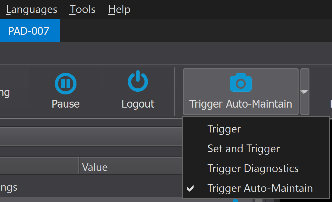
Status messages:
The status messages are displayed in the very bottom part of the PhoXi Control.
Autonomous Maintenance was successfully performed

- Autonomous Maintenance failed (for example, the scene moved)
 Usually, this is caused because the device or the scene has moved during the acquisition, the scene does not contain enough 3D data or the 3D parameters are set incorrectly (e.g. under/over exposure. If changing parameters or changing setting does not help, it is recommended to perform a factory reset. If the issue persists, contact our Help Center.
Autonomous Maintenance can be used also via PhoXi API as demonstrated in the AutonomousMaintenanceExample.cpp. (See the API Examples section).
API
Introduction
PhoXi API provides the building blocks necessary for developing your custom C++ or C# application for working with Photoneo devices. All API functionalities are provided directly by the PhoXi Control application, therefore, PhoXi Control has to be always running for your custom application to work with the device.
Starting with PhoXi Control version 1.17.0, we also offer the PhoXi Python API. Documentation for the Python API is maintained separately in the PhoXi Python API section of this Knowledge Base.
The following guide focuses on C++ and C# integrations. It shows how to use the API in several examples. You may start your development based on one of the examples and modify it to suit your specific needs. Microsoft Visual Studio 2015 and CMake are used to demonstrate how to run the API examples.
The technical documentation is located in the file API/API_Manual.html inside the application installation directory.
On Windows OS, the path to the API directory is usually:
Program Files/Photoneo/PhoXiControl-1.16.x/API
On Linux OS, the path to the API directory is usually:
/opt/Photoneo/PhoXiControl-1.16.x/API
Prerequisites
CMake version 3.10 or above. You can download CMake from the following link: www.cmake.org/download/
API Examples
API examples contain source codes together with build instructions (CMake) to bootstrap the development of your custom application based on the PhoXi API.
Full API example, which contains all functionalities provided by the API for the PhoXi 3D Scanner. Settings that are specific for MotionCam-3D are showcased in the MotionCamChangeSettings. For better readability, specific functionalities are provided in the form of additional examples. All examples are located in corresponding folders in the application installation directory in API/examples/CPP or API/examples/C_Sharp.Example name |
C++ |
C# |
You will learn how to |
|---|---|---|---|
ApplyCustomProjection |
✓ |
|
|
AutonomousMaintenance |
✓ |
✓ |
|
BrighteningTexture |
✓ |
|
|
CAPI |
✓ |
|
|
ChangeColorSettings |
✓ |
✓ |
|
ChangeSettings |
✓ |
✓ |
|
ChangeProfile |
✓ |
|
|
ConnectAndGrab |
✓ |
✓ |
|
DaisyChain |
✓ |
|
|
Early Transfer |
✓ |
|
|
ExternalCamera |
✓ |
|
|
GetISCalibParams |
✓ |
|
|
GetProfiles |
✓ |
|
|
GetTemperatures |
✓ |
|
|
JointMarkerSpace |
✓ |
|
|
MarkerDotCorrection |
✓ |
|
|
MaintenanceCommands |
✓ |
✓ |
|
MinimalOpenCV |
✓ |
|
|
MinimalPcl |
✓ |
|
|
MotionCamChangeSettings |
✓ |
✓ |
|
MovementCompensation |
✓ |
|
|
PointCloudCalculation |
✓ |
✓ |
|
PTPTime |
✓ |
✓ |
|
ReadPointCloud |
✓ |
|
|
Recording |
✓ |
✓ |
|
ReprojectionToExternalCamera |
✓ |
|
|
RotatedCalibration |
✓ |
|
|
TwoScanners |
✓ |
|
|
TwoScannersMultithread |
✓ |
✓ |
|
WinForms |
✓ |
|
|
Full API Example |
✓ |
✓ |
|
Running the Examples
Windows OS
To run the examples on the Windows operating system you will need CMake and Microsoft Visual Studio:
Copy the content of any of the directories, e.g.
API/examples/CPP/ConnectAndGrab_CPPto your custom directory (This is only necessary when you want to edit the source code. Originally, the source code is located inside the Program Files directory, so you will need admin rights to change the file).Launch CMake:
Choose the source and destination directory.
Click the Configure button, specify
Visual Studio 14 2015 Win64or newer as the generator for the project, and confirm with the Finish button. Supported toolsets are v120 and v140 ( also compatible with v141 and v142).

Wait until the configuration is completed, then click the :guilabel:`Generate`button.
In the destination directory, open the file ConnectAndGrab.sln.
Set the project ConnectAndGrab as a StartUp Project (in the right context menu).
Rebuild the solution in Visual Studio (Menu → Build → Rebuild Solution).
Make sure that the PhoXi Control application is running.
In Visual Studio, hit F5 to run the example (
Menu → Debug → Start Debugging)While the example is running, switch back to the PhoXi Control application - every frame captured by the camera is displayed in the Viewer pane.
Linux OS
Copy the folder with the example to your home directory.
$ cd ~
$ cp -r /opt/Photoneo/PhoXiControl-1.16.x/API/examples/CPP/FullAPI/ ./FullAPI
Create a new directory for the build.
$ mkdir dev
$ cd dev
Prepare your project with CMake. The build type can also be Debug.
$ cmake ../FullAPI . -DCMAKE_BUILD_TYPE=Release
Compile the program.
$ make
Run the program.
$ ./FullAPIExample_Release
API and Multiple Versions of PhoXi Control
When multiple versions of PhoXi Control are installed on one computer, the exact path to the PhoXi Control installation directory has to be specified in the find_package(PhoXi) command in the project’s CMakeList.txt file, e.g.:
$ find_package(PhoXi REQUIRED CONFIG PATHS "C:/Program Files/PhotoneoPhoXiControl-second")
Note
Starting with PhoXi Control 1.17, a warning notification appears if an application utilizing a newer version of the PhoXi API attempts to connect to a running instance of PhoXi Control. This alert is designed to prevent unexpected behavior, communication errors, or missing settings that may occur due to version mismatches between the API client and the host application.
Logs
PhoXi API creates a PhotoneoLogFiles folder in the current project directory. To change the directory where this folder should be created please use the environment variable PHO_LOG_FILES_DIR.
Examples:
Absolute path:
PHO_LOG_FILES_DIR=C:\\my_logs
All logs from the client application will be saved in C:\my_logs\PhotoneoLogFiles
Relative path:
PHO_LOG_FILES_DIR=my_app_logs
Client application that runs from folder C:\\my_app will create logs in C:\\my_app\\my_app_logs\\PhotoneoLogFiles
Scanning Guide
How to Scan
Arrange the scene for optimal scanning quality. See Factors Affecting the Quality of Scan.
Put the device into optimal scanning distance. Consult the datasheets which can be found on the Photoneo website for further details.
Adjust scanning parameters for optimal results. See Scanning parameters.
Factors Affecting the Quality of Scan
The quality of the scan depends on a number of different factors. The devices provide a variety of settings that help to perform an optimal scan. Before you decide to change the scanning settings, try to rearrange the scene to ensure the best conditions for scanning. Changing the position of the device with regard to the scene can also make the results of the scan better.
Distance: Closer objects have a better spatial resolution and generally have less noise.
Material albedo (reflectivity): Material with a higher albedo provides a better signal-to-noise ratio. Albedo is defined as a measure of the material’s reflectivity or the degree to which the material will reflect the incoming radiation. The higher the albedo, the more radiation the material reflects from its surface. Generally, brightly colored materials have a higher albedo than darker colored ones, but color alone is not the most reliable indicator of albedo, because radiation has many components outside the visible spectrum.
Strong ambient light: Indoor ambient light generally does not influence the scan very much. However, very strong light such as direct sunlight might be a problem, especially when scanning outdoors. Try to remove all direct sunlight, e.g. by closing window blinds or by moving the installation to a different place. Additionally, Ambient Light Suppression can be used with specific Photoneo 3D Sensors.
Reflections: Non-glossy, matte materials are typically scanned with high-quality results. Even semi-glossy objects are scanned with almost optimal quality. However, glossy, shiny, smooth-sanded, or polished objects often produce specular (mirror-like) reflections - the projected light is reflected out of the sight of the camera. These reflections can significantly lower the scan quality in the corresponding parts of the scan. Additionally, this reflected light can also be reflected onto other parts of the scene. In such cases when the parts are illuminated by reflections from other parts, these secondary “interreflections” can interfere with regular reflections and produce “ghost artifacts”. Metal parts with a high-gloss (or mirror-like) finish are particularly difficult to scan.
Note
A rule of thumb - Take a flat piece of the material you wish to scan and try to look into it as you would into a mirror. If you are able to recognize the shape of your head in the reflection, the material is glossy. In scenes containing such objects, some of them may not be scanned optimally.
When scanning glossy objects, find a position where the light from the projection unit does not illuminate other objects in the scene as this causes interreflections.
Translucent objects: It is possible to scan semi-translucent objects to a certain extent, however, the scattering of light inside the material may reduce the accuracy of the scan of the object’s surface. Materials with a high degree of translucency (near transparent) cannot be scanned.
Assessing the Quality of the Scan
First, do a quick visual check of the scan in the PhoXi Control application. Switch to the 3D Viewer tab. Do you see all parts of the object? Use the mouse to rotate the scene or the mouse wheel to zoom in or out.
For a more advanced assessment, switch to the Confidence Map. This tab displays the estimated deviation of the measured distance. Darker map areas have been scanned with lower error rates, while brighter areas show parts of the scene in which the error rate might be higher, indicating that these sections may be problematic.
Scanning Parameters
Before using any of the devices, it is useful to become familiar with the basics of structured light projection. Please ask your sales representative for more detailed materials and webinars on this topic.
The scanning process consists of three phases:
Capturing (or acquisition)
Processing (computation)
Transfer
Scanning parameters cover the first two phases: capturing and processing. The transfer is affected by the amount of selected data as defined in the Output structure. In addition, scanning parameters also contain settings for changing the coordinate system of the point cloud.
Capturing parameters (MotionCam-3D, MotionCam-3D Color)
General Settings |
||
Operation mode |
Camera Scanner 2D |
MotionCam-3D can operate in 3 modes controlled by this setting.
|
Laser Power |
0 - 4095 |
Controls the intensity of the projected light. By default, it is set to the highest possible value. Decrease the value in case of overexposure. Note: The ‘Laser Power’ setting, adjustable from 0 to 4095, controls the relative output of the laser. Note that the actual power output can vary between individual devices, even when set to the same ‘Laser Power’ value. |
LED Power |
0 - 4095 |
Enables to decrease the LED light intensity used to capture texture. Useful for cases when the texture is used for extracting additional information and is experiencing overexposure. |
Maximum FPS |
0 - unlimited |
Useful for limiting FPS in freerun mode. If you want to allow scan every 10 seconds, set Maximum FPS to 0.1. |
Hardware Trigger |
true/false |
Usually used when two or more devices need to be synchronized. When MotionCam-3D is in hardware trigger mode and a scan is triggered, the acquisition will start after a specified edge of the signal is detected on the trigger input pin. MotionCam-3D can also signalize to other devices that it is acquiring by keeping the trigger output signal in the high state. |
Hardware Trigger Signal |
Falling Rising Both |
Specifies what type of signal is used to trigger MotionCam-3D. |
Maintenance Mode |
Off Auto |
|
Projection Offset (Left/Right) |
0 - 512 |
This parameter narrows the area covered by the projection, shortens the shutter window, and thus limits the ROI of the device. It determines the number of projection columns that are cut off from the left/right side of the projection. The total width of the projection is 512 columns. It is useful for cases where the surroundings of the scanned object interfere with the scan or are unnecessary for further use of the point cloud. Additionally, the sensor’s shutter window length is adjusted to match the narrowed projection, allowing less ambient light to enter the sensor. This parameter can help in scenes with extreme ambient light levels. |
ISO |
100-360 |
This value can be adjusted to modify the primary sensor’s sensitivity to light. Higher ISO means the image will be brighter, however, high ISO values introduce noise which can affect the quality of the texture and also of the point cloud. Adjusting this parameter can improve performance on scenes with high levels of ambient light. |
Early Transfer (MotionCam-3D Color only) |
Off ColorCameraImage |
Early Transfer is a latency-optimization feature designed for high-performance processing pipelines. When enabled, the device transmits the selected texture/image data as a separate frame as soon as it becomes available, before the rest of the 3D data is ready.
When this option is selected, ColorCameraImage must be enabled in Output Structure. We recommend setting Camera Space = ColorCamera to achieve 1:1 alignment between 3D data and the ColorCameraImage/Texture without additional processing. |
Log Level |
Trace Debug Info (default value) Warning Error Critical No Logs |
Different levels of logging. High logging level may subtly affect runtime. |
Color Settings (MotionCam-3D Color, PhoXi 3D Scanner Gen3) |
||
White Balance (Color Settings) |
Allows users to adjust individual red, green, and blue channels’ presence in the RGB texture and ColorCameraImage. It also contains different custom presets to choose from and can be turned off completely. |
|
ROI (region-of-interest) (Color Settings) |
ROI settings allow the user to specify a region, an area, of the scan to focus on. This allows the user to disregard anything outside the given specified region, which in turn decreases the size of the scan and makes it possible to transfer, while also keeping higher resolution of the scan. The settings consist of four numbers:
These numbers represent the X and Y coordinates of the start and the end of the ROI. Note: To take this setting into consideration, you need to turn the ROI Mode to “Custom”. Otherwise the coordinates in this setting will not be taken into account. Note: ROI is also available through API |
|
Exposure (Color Settings) |
0.32 - 100 ms |
This setting allows the user to adjust the exposure of the RGB camera unit in the MotionCam-3D Color and PhoXi 3D Scanner Gen3 independently from the 3D data acquisition. |
ISO (Color Settings) |
50 - 12800 |
This value can be adjusted to increase the RGB sensor’s sensitivity to light. Higher ISO means the image will be brighter, however, high ISO values introduce noise which can affect the quality of the RGB data. |
Gamma (Color Settings) |
0 - 1000 |
The brightness of the RGB data can be adjusted by applying gamma correction. It will be applied after hitting Set or Set and Store By altering these settings, data are changed also in the API, while the gamma correction in the Visualisation setting pane only affects the way the data is displayed in the GUI. |
Resolution (Color Settings) |
1288 x 730 1932 x 1096 2576 x 1460 3864 x 2192 |
This setting will not affect the resolution of the 3D data. It only changes the resolution of the ColorCameraImage (Color in the 2D image tab). If the Camera Space is set to ColorCamera, the depth map resolution is determined by the ColorCameraImage resolution and it is used as Texture. |
Remove False Colors |
true/false |
Solution to address falsely colored points caused by occlusions in the perspective of the color camera unit |
ROI Mode |
Standard Extended Custom |
Note: ROI Mode is available also through API |
Camera Mode (MotionCam-3D, MotionCam-3D Color) |
||
Exposure |
10 - 100 ms |
Data acquisition time: In the camera mode, the duration of the laser line sweeps across the scanned area. |
Resolution (Read-only) |
1120 x 800 1288 x 730 1932 x 1096 2576 x 1460 3864 x 2192 |
Resolution of the depth map. It is a read-only parameter:
|
Sampling Topology (Read-only) |
Standard |
Defines the topology of sensor pixel modulations used for 3D data computation. Currently, only “Standard” sampling topology is supported. |
Output Topology |
Raw Irregular grid Regular grid Full grid |
Defines the structure of the point cloud.
|
Coding Strategy |
Normal Interreflections High-frequency Sparse |
Coding strategy changes the shape of the patterns modulated by the camera sensor (MotionCam 3D) with the aim of lowering interreflections in the scene. The coding strategy optimized for Interreflections uses advanced digital coding that enables the repression of some diffuse interreflections. Interreflections Coding strategy makes the projected light stripes very similar in width, while Normal makes the stripes go from very thick to very thin across the projected patterns. High-frequency is used to suppress interreflections on shiny objects. Additionally, it is useful for scanning of semi-transparent surfaces. Sparse Coding strategy uses Photoneo’s unique COMPIS (Computational Image Sensor) and the Parallel Structured Light technology to enhance signal readouts on transparent, translucent, and glossy surfaces. Suitable for static scenes only and is available only on MotionCam-3D (Color) product line, using the Camera mode. MotionCam-3D - uses a Normal strategy by default. Interreflections Coding Strategy has a lower effect than the Phoxi 3D Scanner. |
Texture Source |
Laser Laser (Enhanced) LED Color |
Determines the way the Texture is acquired.
|
Scanner Mode (MotionCam-3D, MotionCam-3D Color) |
||
Resolution (Read-only) |
1680 x 800 |
Resolution of the depth map. It is a read-only parameter:
|
Shutter Multiplier |
1 - 50 |
Increases scanning time and amount of used light by repeating the projection of each pattern. Shutter Multiplier helps with
|
Scan Multiplier |
1 - 10 |
Increases scanning time by repetition and averaging the scanning sequence. Scan Multiplier helps to increase the signal-to-noise ratio and brings higher contrast in situations where a high dynamic range is required and a shutter multiplier leads to overexposure. |
Coding Strategy |
Normal Interreflections High-frequency |
Coding strategy changes the shape of the projected light patterns with the aim of lowering interreflections in the scene. The coding strategy optimized for Interreflections uses advanced digital coding that enables the repression of some diffuse interreflections. Interreflections Coding strategy makes the projected light stripes very similar in width, while Normal makes the stripes go from very thick to very thin across the projected patterns. High-frequency Coding strategy is suitable for scenes containing reflective surfaces. MotionCam-3D - uses a Normal strategy by default. Interreflections Coding Strategy has a smaller effect than the Phoxi 3D Scanner. |
Coding Quality |
Fast High Ultra |
Determines the number of used patterns and the subpixel accuracy:
This parameter also influences both scanning and processing time. Selection between Ultra and High should be made based on specific scenes. Ultra is usually useful for long-distance scanning with the L or L+ models. |
Texture Source |
LED Computed Computed (Enhanced) Laser Laser (Enhanced) Focus Color |
Determines the way the Texture is acquired.
|
Exposure |
10 - 40 ms |
In scanner mode, the length of exposure of one pattern. (16 patterns + texture by default). |
Capturing parameters (PhoXi 3D Scanner, Alpha 3D Scanner)
General Settings (PhoXi 3D Scanner, Alpha 3D Scanner) |
||
Log Level |
Trace Debug Info (default value) Warning Error Critical No Logs |
Different levels of logging. High logging level may subtly affect runtime. |
Capturing Settings (PhoXi 3D Scanner, Alpha 3D Scanner) |
||
Basic / Shutter Multiplier |
1 - 50 |
Increases scanning time and amount of used light by repeating the projection of each pattern. Shutter Multiplier helps with
Setting high values of the Shutter Multiplier can lead to overexposure and cause missing points in the point cloud. |
Basic / Scan Multiplier |
1 - 50 |
Increases scanning time by repetition and averaging the scanning sequence. Scan Multiplier helps to increase the signal-to-noise ratio and brings higher contrast in situations where a high dynamic range is required and a shutter multiplier leads to overexposure. |
Basic / Resolution |
PhoXi 3D Scanner Gen2 2064 x 1544 1032 x 772 PhoXi 3D Scanner Gen3 2064 x 1544 1854 x 1548 1236 x 1032 1032 x 772 924 x 774 Alpha 3D Scanner 1440 x 1080 |
This parameter adjusts the resolution of the depth map. PhoXi 3D Scanner supports high (2064 x 1544) and half (1032 x 772) resolution. Half resolution is achieved by binning pixels. Benefits of lower resolution:
|
Basic / Camera Only Mode |
true/false |
In this mode, the internal camera is used to capture 2D images of the scene. This setting is useful when it is necessary to navigate the Scanner around the scene or to take a quick snapshot to look for changes in the scene. The captured images can be read as Texture. The setting does not perform any computations necessary for 3D scanning and therefore has low latency. |
Advanced / Ambient Light Suppression |
true/false |
Special acquisition method which limits the effect of ambient light. When Ambient Light Suppression is set to True, increase Shutter Multiplier and Single Pattern Exposure. It is recommended to set LED Shutter Multiplier to non-zero value
|
Advanced / Coding Strategy |
Normal Interreflections High-frequency |
Coding strategy changes the shape of the projected light patterns (Phoxi 3D Scanner). The coding strategy optimized for Interreflections uses advanced digital coding that enables the repression of some diffuse interreflections. Interreflections Coding strategy makes the projected light stripes very similar in width, while Normal makes the stripes go from very thick to very thin across the projected patterns. High-frequency Coding strategy is suitable for scenes containing reflective surfaces. Phoxi 3D Scanner - for most scenes, choosing the interreflections strategy will provide better output, but in some specific situations, the Normal strategy might be useful. |
Advanced / Coding Quality |
Fast High Ultra |
Determines the number of used patterns and the subpixel accuracy:
This parameter also influences both scanning and processing time. Selection between Ultra and High should be made based on specific scenes. Ultra is usually useful for long-distance scanning with the XL model. |
Advanced / Texture Source |
PhoXi 3D Scanner Gen2 LED Computed Laser Focus PhoXi 3D Scanner Gen3 LED Computed Computed (Enhanced) Laser Laser (Enhanced) Focus Color Alpha 3D Scanner LED Computed Computed (Enhanced) Laser Laser (Enhanced) Focus |
Determines the way the Texture is acquired.
|
Advanced / Single Pattern Exposure |
10 - 100 ms |
Increases acquisition time by prolonging the projection of each pattern. The longer the time the more light is projected on the scene. Has the same effect as Shutter Multiplier, but offers more variability in choosing the right value. In combination with Ambient Light Suppression, use values above 40 ms. |
Advanced / Maximum FPS |
0 - inf |
Useful for limiting FPS in freerun mode. If you want to allow a scan every 10 seconds, set Maximum FPS to 0.1. |
Advanced / Laser Power |
0 - 4095 |
Controls the intensity of the projected light. By default, it is set to the highest possible value. Decrease the value in case of overexposure. Note: The ‘Laser Power’ setting, adjustable from 0 to 4095, controls the relative output of the laser. Note that the actual power output can vary between individual devices, even when set to the same ‘Laser Power’ value. |
Advanced / Projection Offset (Left/Right) |
0 - 512 |
This parameter narrows the area covered by the projection, shortens the shutter window, and thus limits the ROI of the device. It determines the number of projection columns that are cut off from the left/right side of the projection. The total width of the projection is 512 columns. It is useful for cases where the surroundings of the scanned object interfere with the scan or are unnecessary for further use of the point cloud. Additionally, the sensor’s shutter window length is adjusted to match the narrowed projection, allowing less ambient light to enter the sensor. This parameter can help in scenes with extreme ambient light levels. |
Advanced / LED Power |
0 - 4095 |
Enables to decrease the LED light intensity used to capture texture. Useful for cases when the texture is used for extracting additional information and is experiencing overexposure. |
Advanced / LED Shutter Multiplier |
0 - 20 |
Increases scanning time and amount of used light to capture texture. |
Advanced / Hardware Trigger |
true/false |
Usually used when two or more devices need to be synchronized. When the device is in hardware trigger mode and a scan is triggered, the acquisition will start after a specified edge of the signal is detected on the trigger input pin. The device can also signalize to other devices that it is acquiring by keeping the trigger output signal in the high state. |
Advanced / Hardware Trigger Signal |
Falling Rising Both |
Specifies what type of edge of the signal on the trigger input pin is used to hardware trigger the device. |
Advanced / Maintenance Mode (PhoXi 3D Scanner Gen3 only) |
Off Auto |
Maintenance mode can be used to check and improve consistency of the device calibration.
|
Advanced / ISO (PhoXi 3D Scanner Gen3 and Alpha 3D Scanner only) |
100 140 200 280 400 560 800 1120 1600 |
This value adjusts the primary sensor’s sensitivity to light. Higher ISO brightens the image and reveals more detail in dark regions, but also increases noise and the risk of oversaturation in bright areas, which can degrade the quality of the texture and the point cloud. Base value: 100.
|
Advanced / HDR (PhoXi 3D Scanner Gen3 only) |
Off Medium Strong |
Controls how well bright regions are preserved (by reducing oversaturation) while keeping dark‑region detail constant. The higher the HDR setting, the better the bright region preservation. HDR helps preserve highlights at medium and high ISO values. At the lowest ISO, HDR has no effect. |
Early Transfer (PhoXi 3D Scanner Gen3 only) |
Off ColorCameraImage |
Early Transfer is a latency-optimization feature designed for high-performance processing pipelines. When enabled, the device transmits the selected texture/image data as a separate frame as soon as it becomes available, before the rest of the 3D data is ready.
When this option is selected, ColorCameraImage must be enabled in Output Structure. We recommend setting Camera Space = ColorCamera to achieve 1:1 alignment between 3D data and the ColorCameraImage/Texture without additional processing. |
Processing Settings (Photoneo 3D Sensor)
Data Cutting / 3D ROI |
Camera Space Min.-Max. X, Y, Z Point Cloud Space Min.-Max. X, Y, Z |
Defines data cutting volumes in Camera or Point Cloud space. This setting can be configured manually via numerical input or via the Interactive Mode in the 3D Viewer. For detailed instructions and Interactive Mode usage, see chapter 3D ROI Configuration |
Data Cutting / Normal Angle |
Max Camera Angle 0 - 90° |
Maximal angle accepted between the camera-to-3Dpoint straight line and the measured normal vector at this point. (can be understood as “how much the scanned surface is rotated away from the camera”). |
Max Projection Angle 0 - 90° |
Maximal angle accepted between the projector-to-3D-point straight line and the measured normal vector at this point. (=“how much the scanned surface is rotated away from the laser projector”) 3D points with normals rotated away above these thresholds will be filtered out. Useful for scanning objects where edges are causing problems. |
|
Min Halfway Angle 0 - 90° |
Minimal angle accepted between the “halfway line” to a 3D point and the normal vector in this point. The halfway line is the center line between the camera-to-3D point line and the projector-to-3D point line. |
|
Max Halfway Angle 0 - 90° |
Maximal angle accepted between the “halfway line” to a 3D point and the normal vector from this point. |
|
Data Cutting / Max Inaccuracy |
0 - 100 (mm) |
Threshold for filtering the 3D points based on the point measurement reliability. Enables prefiltering of the output data according to the specific needs of your application. Some applications require a more complete device output at the expense of lower precision. Other applications are intended to work with precise data only and need to filter out regions where the precision does not meet a specific criterion. Max Inaccuracy can be set based on data from the Confidence Map. The corresponding parameter in the API is named Confidence. |
Data Cutting / Calibration Volume Only |
true / false |
By default, only the points scanned in the recommended scanning volume are displayed. It is possible to see all the data acquired in the scene by setting the Calibration Volume Only to false. Data outside of the recommended scanning range are not guaranteed to be measured with the same accuracy. Recommended scanning volume is defined by the minimal and maximal scanning distance, which differs between the device models and can be found in the device datasheet. |
Point Cloud Generation / Surface Smoothness |
Sharp Normal Smooth |
Determines the setting of the smoothness of the point cloud generation algorithm.
|
Point Cloud Generation / Normals Estimation Radius |
0 - 4 |
Determines the size of the area (in sensor pixels) around the point that serves for the computation of the normal vector of each 3D point. A higher radius leads to smooth normal vectors and a small radius to noisy normals. With the radius set to 0 normals are not calculated. |
Marker Dot Correction / Operation Mode |
Off Passive Active Reference Recording |
All the operation modes are explained in section Operation Modes |
Marker Dot Correction / Max Marker Shift (pixel) |
0-25 |
Maximal permitted pixel shift of the markers It is not recommended to raise this value above 25 pixels |
Interreflections Filter (PhoXi 3D Scanner, Alpha 3D Scanner only) |
true/false |
Special filter used to remove incorrectly calculated points due to the presence of interreflections. Switching the filter on changes the Coding Strategy to Interreflections. Interreflections occur when the laser light pattern is reflected from a diffuse surface and illuminates nearby objects. If the reflection interferes with the primary light pattern reflected from the scene, the depth calculation is affected causing the existence of discrete patches of points isolated from the rest of the point cloud, and they do not represent reality. |
Interreflection Filter Strength (PhoXi 3D Scanner, Alpha 3D Scanner only) |
0.01 -0.99 |
Allows the user to adjust the strength of the Interreflection Filter. |
Pattern Code Correction |
Off Medium Strong |
Defines strength of the smoothing filter applied onto the decoded projection patterns. |
Pattern Decomposition Reach |
Local Small Medium Large |
This parameter is mostly used to scan objects that are harder to scan due to challenging scanning angles, dark color, or higher shine. It helps to correct or eliminate points that have higher computation errors. To correctly decode the series of light patterns for each pixel, the values of surrounding pixels are taken into account. If the difference between them is larger than expected, the value of the candidate pixel is adjusted. This way some errors that are identified during computation are corrected. If the difference between neighboring pixels is too large, the candidate pixel is filtered out. |
Signal Contrast Threshold (PhoXi 3D Scanner, Alpha 3D Scanner only) |
0 - 4095 |
Serves as a filter that helps to eliminate parts of the scan with low contrast and low quality. Lowering the value of the Signal contrast threshold can help in situations where strong ambient light or worse scanning properties produce insufficient contrast between the light and dark stripes of the pattern. Higher values can serve to eliminate some noise from the scan. Each pattern is composed of light and dark stripes. The difference in intensity between them is called contrast. Two neighboring pixels belong to differently illuminated stripes (one is light and one is dark) if the contrast between them is higher than the threshold set by this parameter. To assess the contrast between light and dark stripes, set the “Focus” texture option within the Texture source setting and examine the resulting contrast in the Texture image. |
Glare Compensation |
true/false |
Filter to suppress 3D reconstruction deficiencies caused by glare from a strong reflection of the scanned subject. |
Hole Filling |
Off Medium |
Hole filling feature, if enabled, supplements 3D points to gaps surrounded by points in reasonably small depth range. Gaps surrounded with largely varying depths will not be filled. Default: Off |
Coordinate Settings (Photoneo 3D Sensor)
Primary Camera to Point Cloud Space transformations
Transformation matrix |
||
CameraSpace |
PrimaryCamera |
Match (identity matrix) |
CameraSpace |
ColorCamera |
Transformation between primary camera and color camera |
MarkerSpace |
PrimaryCamera |
Transformation between the primary camera and the marker space |
MarkerSpace |
ColorCamera |
Transformation between the primary camera and the marker space |
PrimaryCameraSpace |
PrimaryCamera |
Match (identity matrix) |
PrimaryCameraSpace |
ColorCamera |
Match (identity matrix) |
Robot/CustomSpace |
PrimaryCamera |
Transformation between the primary camera and the robot/custom space |
Robot/CustomSpace |
ColorCamera |
Transformation between the primary camera and the robot/custom space |
Current Camera to Point Cloud Space transformations
Transformation matrix |
||
CameraSpace |
PrimaryCamera |
Match (identity matrix) |
CameraSpace |
ColorCamera |
Match (identity matrix) |
MarkerSpace |
PrimaryCamera |
Transformation between the primary camera and the marker space |
MarkerSpace |
ColorCamera |
Transformation between the color camera and the marker space |
PrimaryCameraSpace |
PrimaryCamera |
Match (identity matrix) |
PrimaryCameraSpace |
ColorCamera |
Transformation between primary camera and the color camera |
Robot/CustomSpace |
PrimaryCamera |
Transformation between the primary camera and the robot/custom space |
Robot/CustomSpace |
ColorCamera |
Transformation between the color camera and the robot/custom space |
The above-mentioned matrices for the Primary Camera to Point Cloud Space transformations and the Current Camera to Point Cloud Space transformations are also available via API.
3D ROI Configuration
3D ROI function defines data cutting volumes in either the Camera or the Point Cloud coordinate space.
Tip
For a step-by-step visual demonstration, you can watch our video tutorial on ROI configuration in an interactive mode here.
General Behavior & Constraints
Processing Order: Cutting is processed after the point cloud is computed; therefore, enabling this setting cannot speed up the transfer time.
Coordinate Spaces: ROI cutting applied in the camera space is always based on the original coordinate system. ROI cutting in the point cloud space is applied only when the coordinate system of the point cloud differs from the camera space.
Tip
Use this setting in combination with Marker Space to remove the background, which will make scan alignment easier.
Configuration Modes
You can define the cutting volumes using either the graphical interactive mode or by manually entering the numerical parameters.
1. Interactive Mode (Graphical)
The Interactive Mode allows you to visually define and modify the cutting volume directly within the 3D Viewer.
Activation
To activate the Interactive Mode for 3D ROI, click the box icon located in the settings pane under: Processing Settings > Data Cutting > 3D ROI > Camera Space (or Point Cloud Space).
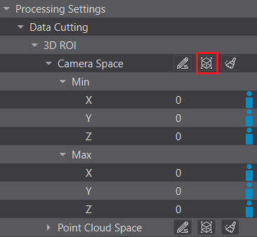
Once activated, a bounding box will appear over your point cloud in the 3D Viewer, along with a dedicated ROI toolbar at the top of the viewer.
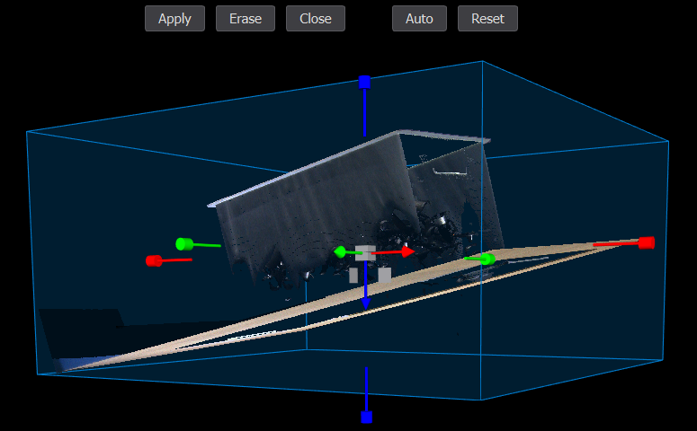
Manipulating the Bounding Box
You can modify the size and position of the bounding box using the interactive 3D widgets attached to it. The axes are color-coded: X (Red), Y (Green), and Z (Blue).
Note
The bounding box is always aligned to the coordinate axes and cannot be rotated.
- Colored Handles (Resize) - Click and drag the red, green, or blue handles located on the faces of the bounding box to stretch or shrink the volume along that specific axis.
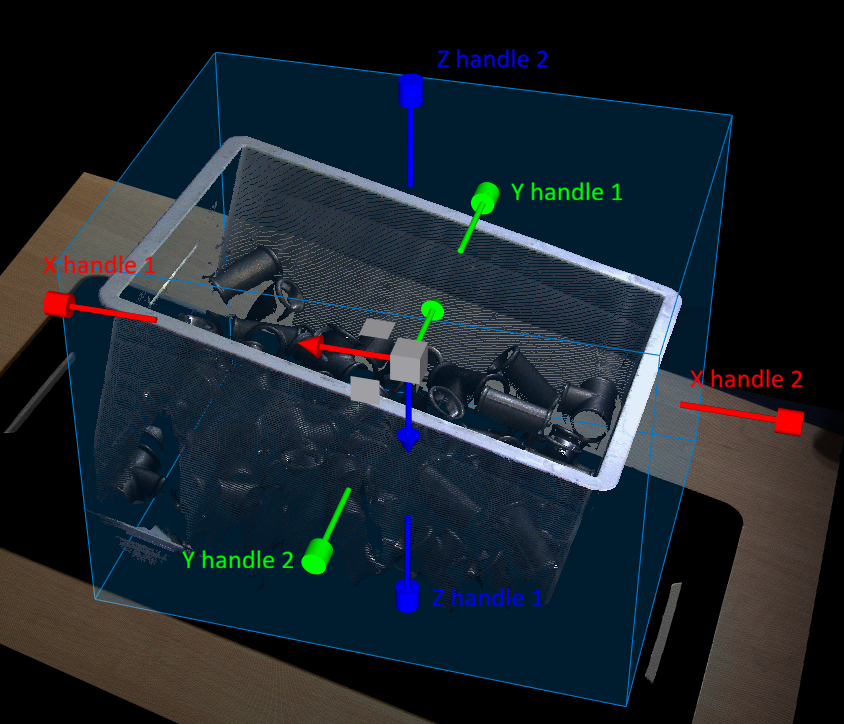
Grey Central Cube (Free Movement) - Click and drag the solid grey cube in the very center to move the entire bounding box freely in 3D space.
- Grey Planar Squares (Planar Movement) - Click and drag one of the grey square markers (located near the center) to move the entire bounding box strictly along its corresponding 2D plane (X-Y, X-Z, or Y-Z).

ROI Toolbar Controls
While in Interactive Mode, a new toolbar appears at the top of the 3D Viewer. Use these buttons to manage your ROI session.

Apply - Confirms your adjustments. The Min and Max coordinate values in the settings panel will update automatically to match the visual box.
Note
To see the actual cut applied to a new scan, you must hit the main Set and Trigger button.

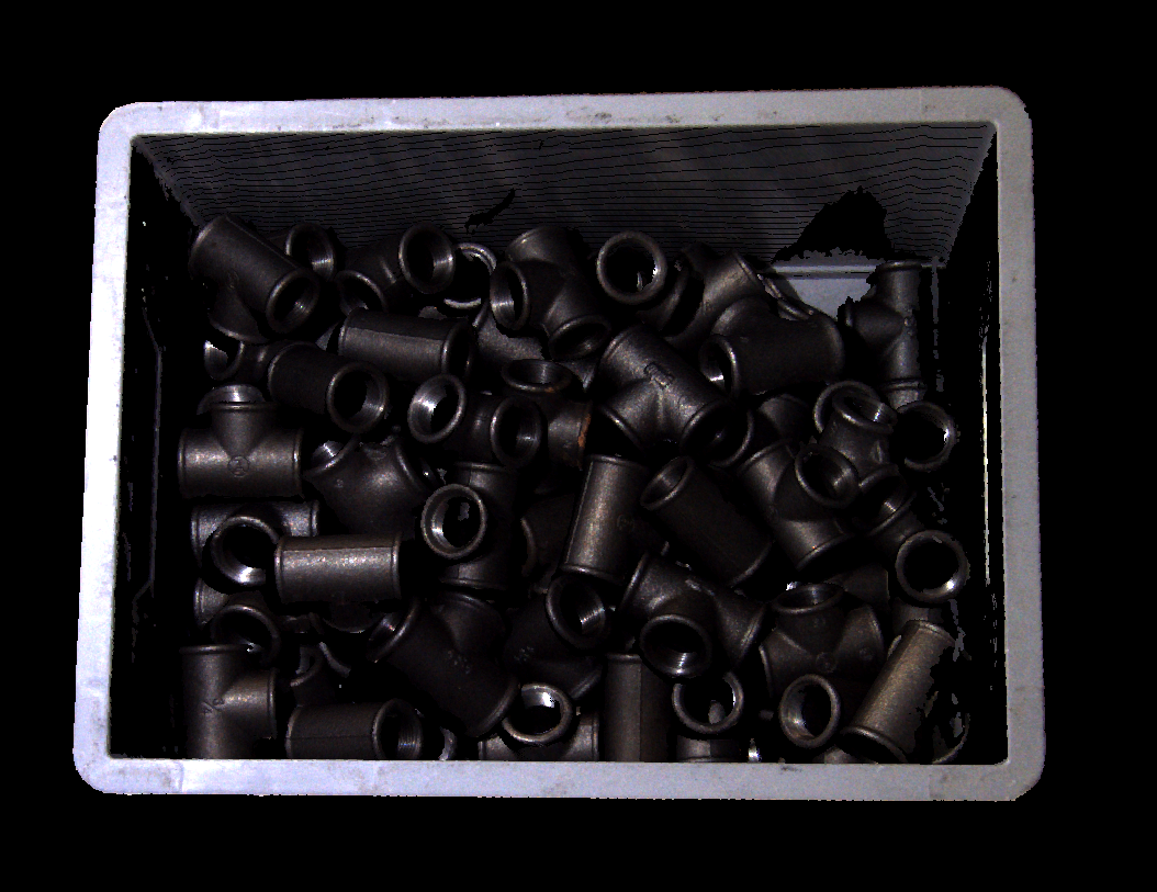
Erase - Clears the current bounding box and sets all boundary values to 0 (which disables data cutting).
Auto - Automatically sizes and positions the bounding box to encapsulate all valid points in the point cloud.
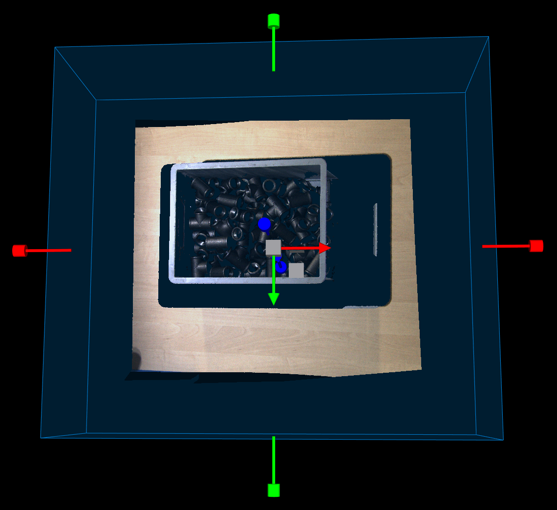

Reset - Reverts the bounding box back to the exact dimensions it had before you started the current interactive session.
Close - closes the interactive ROI mode.
2. Manual Mode (Numerical)
You can manually define the cutting volume by inputting exact boundary values. You have two options for entering these parameters:
- Start filling out the Min and Max values for all three coordinates directly in the settings pane.

- Click the pencil icon to open the dedicated coordinate table and fill in the values.

Configuration Rules & Constraints
When manually defining the ROI, the system applies the following rules to your inputted values:
The cutting will be applied only if the minimum value is strictly smaller than the maximum value for a given axis (e.g., min. X is smaller than max. X).
Setting any boundary value to 0 disables data cutting in that specific direction.
If cutting close to 0 is necessary, use a small decimal value instead.
Hardware trigger
The hardware trigger provides the user with means of triggering devices by external means - outside of the software environment. To get further hardware specifications about the hardware trigger, see the Photoneo 3D Sensor User Manual. This functionality is mostly used for synchronization purposes:
With external events, such as an object arriving inside the field of view of Photoneo 3D Sensor (i.e. triggered by an optical gate)
With other devices, such as 2D cameras, PLCs, etc.
With multiple Photoneo 3D Sensors
Software Configuration
The supported uses cases are:
Single device triggered by HW trigger
Example: A MotionCam-3D Color triggered by an optical sensor to capture a moving object on a conveyor belt
A device sending an output signal to a PLC
Example: A MotionCam-3D sends an output signal to a robotic controller after the acquisition to start a solution. Locator Studio picking from a moving conveyor belt.
Multiple devices triggered by HW trigger independently from each other
2 Photoneo 3D Sensors triggered by a PLC with a specific delay
Two or more devices triggered sequentially in a chain → Daisy chain
PhoXi Instant Meshing model creation
Two or more devices triggered sequentially in a loop → daisy chain in a loop
Simple configurations
Single device triggered by HW trigger (SEXT)

The device can be triggered with a software (default) or a hardware trigger. There is a dedicated parameter in PhoXi Control / PhoXi API to control device trigger mode. To trigger the device via hardware trigger:
Set Hardware Trigger = TRUE
Put the device into freerun
Send the signal to trigger input
With hardware trigger mode enabled, the device will capture a new scan each time an input signal is detected. If the trigger input signal arrives during an active device acquisition, it will be ignored. To stop the device from listening to the hardware trigger signal, turn the freerun OFF. To disable hardware trigger mode, set the Hardware Trigger = FALSE. The response to the trigger signal is around 3 ± 2 milliseconds.
Photoneo 3D Sensor output signal to PLC or other device (OUT)

Photoneo 3D Sensor sends a signal to trigger a secondary device, which can be a PLC or other signal acceptor.
Multiple devices triggered by HW trigger independently from each other (MEXT)
In this case, an external trigger would be triggering 2 or more devices independently. The devices need to be set up the same way as in the previous use case with a single device. If the devices’ FOVs (fields of view) overlap, make sure the input signals are timed adequately in order to acquire 3D data without any distortions caused by the projection interference.

Daisy Chain and Daisy Chain in a Loop
Daisy chain and daisy chain in a loop are special setups in which two or more Photoneo 3D Sensors are interconnected and are triggered consecutively by each other. They are mostly used to prevent interference between two projections if the devices have overlapping fields of view. In a daisy chain, the trigger sequence is always triggered by external means. In a daisy chain in a loop, once the acquisition has started it will continue until the loop is broken.
Two or more devices triggered sequentially in a daisy chain (EXTSEQ, INTSEQ)
In a daisy chain consisting of, for example, 4 devices, the output pin of the first device is connected to the trigger input of the second device. The output of the second device is connected to the input on the third device and so on. The output on the last (fourth device) is not connected to any Photoneo 3D Sensor (but can be connected to a different device).
There are two options on how to set up the chain:
Sequential triggering with external signal source - EXTSEQ
Set
Hardware Trigger = TRUEon all devices.Start freerun on all devices. In this scenario nothing will happen unless
Hardware trigger from an external source is sent to the trigger input of the first device in the chain

Sequential internal triggering - INTSEQ
Set
Hardware Trigger= TRUE on the last three devices and put them into freerun.Trigger the first device by software trigger/ freerun. This will start the chain and trigger all consecutive devices.
In case the freerun is used, to stop the acquisition of all devices, it is necessary to disable freerun on the first device

Limiting the FPS in some applications might be necessary to achieve stable results. For example, we can have 4 MotionCam-3Ds with overlapping FoVs of which one is primary and it is running on freerun (via PhoXi Control or API) which triggers the other 3 secondary devices via the hardware trigger (connected in series). If, theoretically, the acquisition takes 15 ms for each MotionCam-3D and the Maximum FPS is set to 20 (frame every 50 ms), there is enough time to trigger only 2 secondary devices and part of the acquisition of the last device would be overlapping with the following frame on the primary device. If we limit the FPS of the primary device to 15 (frame every 66 ms), there is enough time to trigger all secondary devices to avoid overlapping. The acquisition windows of the secondary device and tertiary device need to fit in the window between the frames of the first device.
Two or more devices triggered sequentially in a loop - daisy chain in a loop (EXTDCL)
This case is very similar to the basic daisy chain explained above. We can have 4 devices, where the output pin of the first device is connected to the trigger input of the second device. The output of the second device is connected to the input on the third device and so on. However, in this case, the output signal from the last device is connected to the input of the first device, creating a loop.
The picture below illustrates the daisy chain loop with three devices. The red rectangle represents the time period in which the device is in acquisition (the laser is sweeping the scene). During this time period the signal, which is represented by the black line, is opposite to what it was before the acquisition. Once the acquisition on the first device is finished, the signal changes back and thus produces a trigger signal (blue arrow) for the second device that is connected to the first one. A few milliseconds later the acquisition on the second device is started. The yellow rectangle represents the delay between when the trigger signal is received and when the acquisition starts. This delay is typically around 3 milliseconds.

Simplified signal representation for 3 devices in a daisy chain in a loop
In these setups, the end of acquisition on MotionCam-3D #1 produces a falling edge on its output pin which triggers acquisition on MotionCam-3D #2. This is followed by the acquisition on the MotionCam-3D #3.
To set up Photoneo 3D Sensors in a daisy chain in a loop configuration:
Set Hardware Trigger = TRUE on all devices.
Enable free run on all devices
Send a signal from an external signal source to initialize the acquisition
To stop the acquisition, disable freerun on one of the devices.

See our API example for the daisy chain to learn how to control the devices via hardware trigger.
Troubleshooting
If the following section does not help in solving the difficulty you are experiencing, contact our support team at the Help Center.
The more information that you provide, the faster and more accurate the answer can be. The following section explains how to collect the log files that you are kindly asked to attach to your support requests.
Additionally, please describe what you have been trying to do, what the result was, and what you expected. Depending on the nature of the problem, please also report the version of the operating system being used, your PC configuration, and other additional information that would be helpful in replicating the problem and identifying its root cause.
Collecting Log Files
There are several types of diagnostic information to collect and attach to your support request:
Downloading Logs From Device
Logs from the device can be downloaded using
A built-in functionality of PhoXi Control
A stand-alone utility for downloading logs from device
Tip
It is recommended to set up your error handling process to collect the logs immediately after experiencing any issue with the device.
PhoXi Control built-in functionality
- In the Network Discovery, click the Utils button (previously Maintain) in the bottom right corner and choose the Log Downloader option.
- Follow up the prompt in the window to save the log file in desired location
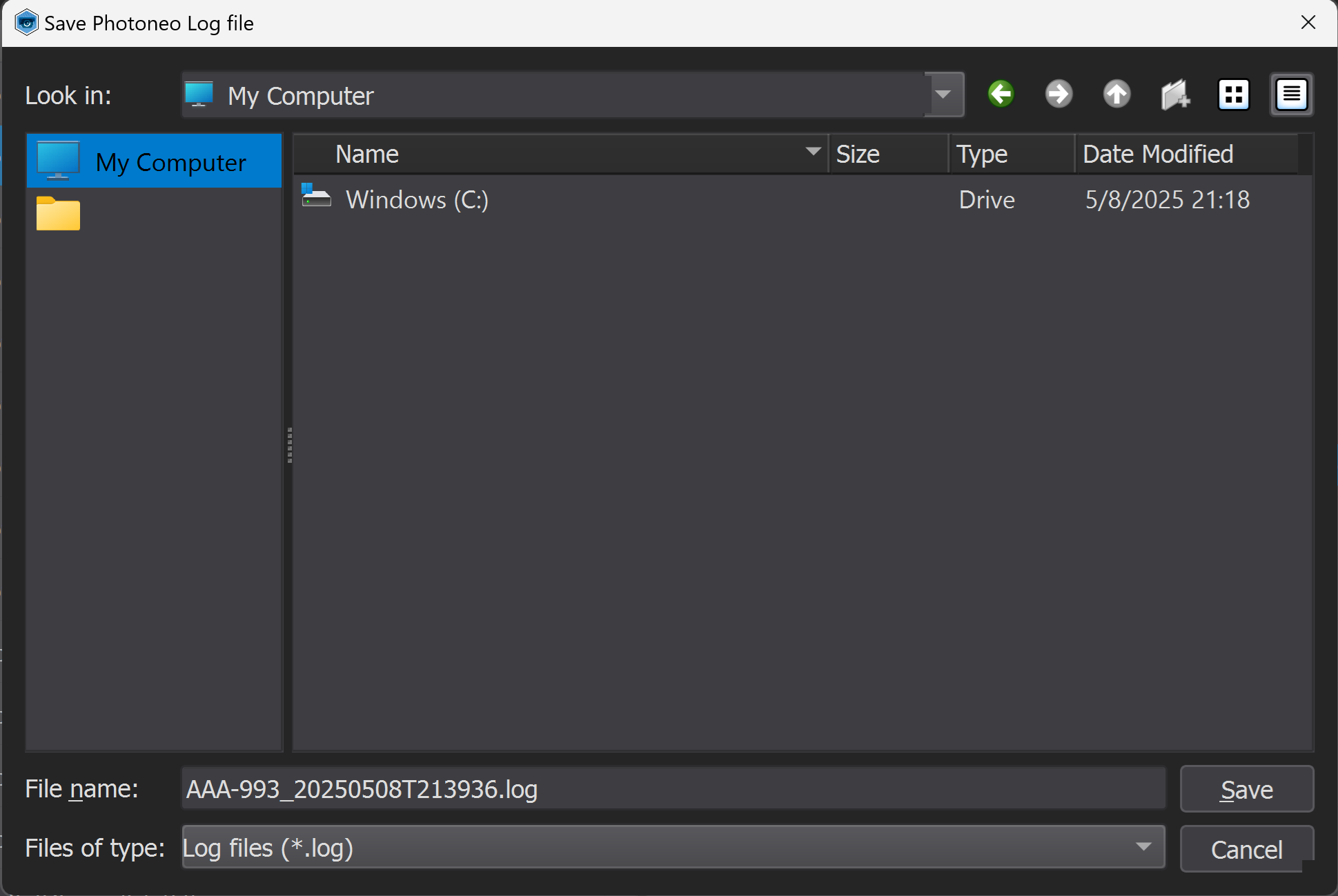
Standalone Log Downloader Utility
Windows
Download the Log Downloader Utility from https://www.photoneo.com/dl/logdl-win.
The Log Downloader has two modes
Interactive mode
Double click the phoxi-log-downloader application
Input device ID or IPv4/IPv6 address upon request
Direct mode
Call the application in command prompt or by your application and supply the ID or IP address of the device
> <name_of_the_chosen_log_downloader> <IPv6>
Once the application finishes (
Result: OK), all the logs are stored in filelog.txtin the folder with the application.Send the file
log.txtto Photoneo Support.
Ubuntu
Download the utility from https://www.photoneo.com/dl/logdl-lin or use the Utils button (previously Maintain) in PhoXi Control as explained in the Log Downloder section.
Open a new terminal in the folder with the application
Give the application executable rights:
$ chmod +x <name_of_the_chosen_log_downloader>
Execute the application with its ID or IPv4 or IPv6 as an argument
$ ./<name_of_the_chosen_log_downloader> <IPv6>
Once the application finishes (
Result: OK), the logs are stored in the filelog.txtwhich was created in the folder with the application.
Device Log Level
By default, the logging level on the device is optimized for performance. To extend the logging level to contain extensive information on PhoXi 3D Scanners, turn on Extended logging in PhoXi Control and reconnect to the device (the logging level is determined at the time of connection to the device.) Extended log level on MotionCam-3D needs to be enabled by our support during the remote sessions.
PhoXi Control Log Files
PhoXi Control log files are located in the application folder:
Windows 10
C:\\Users\\<user>\\AppData\\Roaming\\PhotoneoPhoXiControl\\PhotoneoLogFiles
Ubuntu
~/.PhotoneoPhoXiControl/PhotoneoLogFiles
PhoXi Control Log Level
PhoXi Control always creates basic log files. If you experience any problem with Phoxi Control please collect the logs from the folders mentioned above. If you are able to recreate the problem, please set up Extended Logs:
Open
LogConfig.txtin thePhotoneoLogFilesfolderOn the first line, change
0to10to enable extended logsRestart PhoXi Control
Once you have replicated the issue and collected logs, change the first number in
LogConfig.txtback to0.
PhoXi Control Core Dumps
If you have experienced a crash of PhoXi Control, please collect the core dump located in the ProgramData folder on Windows and in the /tmp folder on Ubuntu. The core dumps are available for all PhoXi Controls with version above 1.2.22:
Windows 10
The core dump generation is enabled automatically during the installation
Location:
C:\\ProgramData\\PhotoneoPhoXiControl\\CrashDumpsThe dump file looks like this:
%ProgramData%\\PhotoneoPhoXiControl\\CrashDumps\\PhoXiControl.exe.6548.dmp
Ubuntu
The core dump generation needs to be enabled first using the following commands:
$ ulimit -c unlimited
$ sudo sysctl -w kernel.core_pattern=/tmp/core.%e.%u.%p.%t.dmp
Note
This will enable the core dump generation for any Linux process, not only PhoXi Control
Location:
/tmpThe dump file looks like this:
/tmp/core.PhoXiControl.1000.5503.1602775821.dmpAfter successful diagnostics, disable the core dump generation using the following command:
$ ulimit -c 0
API Log Files
Client API application does not create logs by default.
To set up API logging (generating a lot of data):
Navigate to your application folder and open
PhotoneoLogFilesfolderOpen
LogConfig.txtand change the value on the first row to10Restart your application
Once you have replicated the issue, you can turn off the logs by changing the first-row value back to
0
The API log files directory can be changed by setting up the environment variable PHO_API_LOG_FILES_DIR or PHO_LOG_FILES_DIR. If PHO_API_LOG_FILES_DIR environment variable is defined, logs will be saved in the direction it points to. If it is not defined, logs are saved in the directory pointed by the PHO_LOG_FILES_DIR. If none of these is defined, the logs will be saved directly on the desktop. In case both of the variables are defined, PHO_API_LOG_FILES_DIR is prioritized.
API Core Dumps
If you are experiencing crashes of your application, you can set up creating crash dumps.
Windows 10
Crash dumps for your application need to be activated in the Windows registry.
Download the following file crashdump.reg
Unzip the archive
Open it in the text editor
Overwrite
UserAPiApp.exewith the name of your application and save the changes. The.exeis a necessary part of the name.Double click on the
crashdump.regand allow it to become part of the Windows registersThe crash dumps should be generated in the same folder as the PhoXi Control crash dump
%PROGRAMDATA%\\PhotoneoPhoXiControl\\CrashDumps
Ubuntu
Type the following command into the terminal:
$ ulimit -c unlimited
$ sudo sysctl -w kernel.core_pattern=/tmp/core.%e.%u.%p.%t.dmp
The crash dumps are generated in the /tmp folder. Here’s an example core dump file: /tmp/core.my_app_name.1000.5503.1602775821.dmp
Troubleshooting Network Connection
Cannot connect to the device or scanning time is too long
The device is listed in the PhoXi Control application, but after trying to connect to it, it disconnects:
Check your ethernet connection speed; the minimum speed should be 1 Gbps.

If your connection is very slow (10 Mbps), the connection will most likely time out.
If your connection is slow (100 Mbps), data transfer will take more time.
Use the Speed test to verify the right connection speed
The device is not visible in PhoXi Control on a network with a dynamic IP assignment
Make sure your device is connected correctly - you are using network media supporting Gigabit Ethernet or higher and your network topology is either star or direct (see sections Network media and Network topology).
Reboot the device.
Check the LED lights on the backside of the device. The last two indicate the status of the Ethernet connection. Please note that the PoE devices have a different set of LEDs than the 12 V devices.
12 V devices

The left diode indicates speed:
ON - 100 Mbps
OFF - other than 100 Mbps, usually 1 Gbps
The right diode indicates Ethernet activity:
OFF - link is down
Flashing - link is up with activity
Steady - link is up without activity
PoE devices:

3rd LED from top:
OFF - link is down
Flashing - link is up with activity
Steady - link is up without activity
4th LED from top:
ON - Gigabit connection
OFF - slower than gigabit connection
Check the network configuration of your computer:
Your firewall is blocking communication with the device.
Zeroconf implementations (Avahi or Bonjour service) are not running or are running incorrectly.
To resolve the problems listed above:
Check your Network Connection status in system settings. If networking is disabled, enable it.
Check if your firewall is not blocking Bonjour Service: www.digitalcitizen.life/how-change-windows-firewalls-list-allowed-blocked-apps
Check the settings of your firewall. The device communicates with the computer on ports - 5353 and 5354 on the computer side and ports - 65499 and 65534 on the device side.
Allow incoming UDP traffic on ports 5353 (mDNS), 5354 (mDNS responder).
Allow outgoing TCP traffic on ports 65499 and 65534.
On Ubuntu (16.04):
Check if avahi-daemon is running.
$ systemctl status avahi-daemon.service
$ systemctl status dbus-org.freedesktop.Avahi.service
$ systemctl status dbus.service
On Windows:
Is Bonjour service installed and running?
Open Windows Task Manager (Ctrl + Shift + Esc) → Services.
Find Bonjour service and check its status.
If it is not running, try to start it.
If starting it fails, open the Event Viewer application.
Go to Windows Logs → Application in the left pane and look for Errors (Event Level column) reported by Bonjour Service (event Source column).
Reinstall Bonjour Service if needed.
Bonjour Service cannot be started on Windows
If you try to start Bonjour Service and it fails due to exception 1067, download the 32-bit version of Bonjour Service from Apple. The name of the 32-bit version is Bonjour Print Services for Windows v2.0.2 and can be found in the following link: support.apple.com/kb/dl999?locale=en_US.
Ubuntu does not show IPv4 address - creating a Link-local connection
When the PhoXi 3D Scanner or MotionCam-3D is connected to Ubuntu and you want to use dynamic IP address assignment relying on Zeroconf, the network discovery usually requires a Link-local connection. It is necessary to create Link-local connection when:
PhoXi Control does not display IPv4 address in the corresponding field
Running the following command does not show
169.254.x.xIPv4 address
$ ip addr show <INTERFACE-NAME>
To create Link-local connection:
Connect the device to your computer.
Find out the system name of the network interface you have used. It is usually
ethNorenpNs0whereNis some small number, e.g.eth0orenp2s0. You can find out the list of network interfaces by typingip -br -c link showninto a terminal window. Your device will be shown as UP. Note that if you use more than one Ethernet interface you’ll see more than one device UP. In that case, disconnect the network cable from the Photoneo device, run theip -br -c link showcommand again to see which one went DOWN, and plug the network cable back again. Note the hardware (MAC) address of the device. In our example, the device isenp2s0and its hardware address is7c:67:a2:9e:57:c3.

Create a new network connection using NetworkManager. In the Ethernet tab, choose the right device (the field is under the Identity tab and called MAC address on some versions of Ubuntu). In the IPv4 Settings choose
Link-local Onlyas the connection method.

Name the connection for example as
Link-local Only Connectionand save its configuration.Activate the connection by clicking on its name in the network connections list in the top right corner of your screen.
In case of other issues
Please report any issues to Help Center.
Please describe what you have been trying to do, what the result was, and what you expected. Depending on the nature of the problem, please also report the version of the operating system being used, your PC configuration, and other additional information that would be helpful in replicating the problem and identifying its root cause. Thank you!
Additional Guides
The following reference topics were previously included here as appendices. They have been moved to the Guides section (under 3D Sensors) for easier navigation: