Every point in a point cloud is identified by three numbers - its XYZ coordinates. Coordinates give the precise position of each 3D point relative to the point of origin of the specific coordinate system.
By default, all Photoneo 3D Sensors are set to generate point clouds in the camera coordinate space (the point of origin is located in the center of the camera sensor). Additionally, they provide the internal capability to real-time transform the point cloud to any arbitrary coordinate space. Once the transformation parameters are known the device generates the point cloud (using 3D rotation and translation) in the selected coordinate system.
In PhoXi Control there are five coordinate spaces to choose from
Camera space
Marker space
Robot space
Custom space
PrimaryCameraSpace
The default setting for all Photoneo 3D Sensors is to use CameraSpace. This coordinate system has a point of origin in the center of the camera sensor.
In PhoXi Control, use the checkbox Axis under the Coordinates box in the right pane to visualize the axis defining the default coordinate system. (XYZ axes follow the RGB color convention).
Camera space in PhoXi Control. Z-axis (blue) lines up perfectly with the direction of the view, so it is not visible.
In the camera space, X-axis aims to the right side of the device, and Y-axis aims downwards. The sensor is mounted at a specific angle relative to the sensor body. This angle varies for different device models, so the XY-plane is not parallel with the outer casing of the device (see Table 1 for details).
Z-axis aims at the scene and defines the “depth” at which the object is observed by the device. It’s the perpendicular distance of every single point on the scene to the XY-plane defined by the camera sensor.
Orientation of camera space coordinate system in relation to the device. The X-axis is red, the Y-axis is green and the Z-axis is blue.
Table 1: Angles at which the camera sensor is mounted in different models of PhoXi 3D Scanner.
Device
XS
S
M
L
XL
Angle
0°
15.45°
11.75°
9.45°
7.50°
Table 2: Angles at which the camera sensor is mounted in different models of Alpha 3D Scanner.
Device
L
XL
Angle
7.50°
7.50 °
Table 3: Angles at which the camera sensor is mounted in different models of MotionCam-3D (Color).
Device
S
S+
M
M+
L
*L+
Angle
0°
0°
0°
0°
0°
0°
* Only available as MotionCam-3D Color
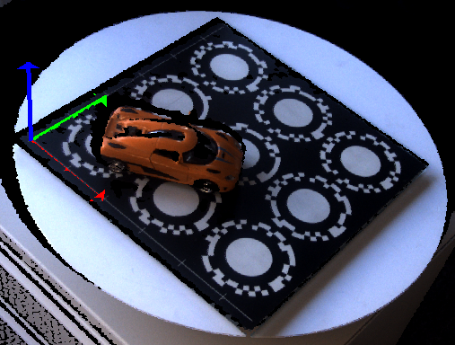
Camera space (left - the origin is in the camera unit of the device) and marker space (right - the origin is in the origin of the marker pattern) in PhoXi Control.
Marker space provides you with a practical tool for many different real-world applications. Marker space transformation is useful in situations like: calibration of a coordinate system with a specific plane, multiple scan alignment (one moving device), multiple device calibration (scanning scene from different directions), or calibration of a device mounted on a moving robot arm.
Marker space has the point of origin and its axes defined by marker pattern:
The origin point lies at the origin point of axes printed on the pattern.
The XY-plane is aligned with the XY-plane visible on the marker pattern. The X-axis and Y-axis match the X-axis and Y-axis printed on the pattern.
The Z-axis points upwards from the marker pattern perpendicular to the XY plane.
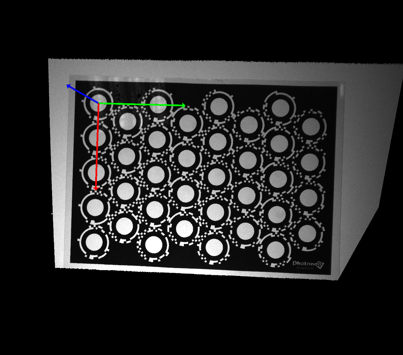
Marker pattern is a specially developed printed pattern recognized by Photoneo 3D sensors used to transform the coordinate system from default camera space to marker space. It contains N uniquely recognizable white circles on black background with encoded coordinates. Marker patterns are available in different sizes - in the PhoXi Control installation folder or for downloading from our website www.photoneo.com/downloads/device-resources/.
Use PhoXi Control Menu → Tools → Marker Patterns to open a folder containing two subfolders. In the subfolder Patterns, you can find PDF versions of all available marker pattern sizes. Since different device models are able to scan different volumes from different distances, they also need different sizes of marker pattern.
Table 3: Recommended sizes of marker patterns for PhoXi 3D Scanner models.
XS
S
M
L
XL
Scanning distance [mm]:
<1900
>1900
A5
✔
A4
✔
✔
A3
✔
✔
✔
A2
✔
✔
S30
✔
✔
✔
✔
✔
Table 4: Recommended sizes of marker patterns for MotionCam-3D models.
S
S+
M
M+
L
L+
<1900
>1900
A5
✔
✔
A4
✔
✔
✔
✔
✔
A3
✔
✔
✔
✔
✔
✔
✔
A2
✔
✔
✔
S30
✔
✔
✔
✔
✔
✔
✔
Table 5: Recommended sizes of marker patterns for Alpha 3D Scanner models.
L
XL
A5
A4
✔
A3
✔
✔
A2
✔
✔
S30
✔
✔
For complete information about minimal/maximal distances and maximal angles from which marker pattern is recognizable by Photoneo 3D Sensors please refer to Table 6, 7, and 8.
Table 6: Sizes, distances, and angles at which the marker pattern is still recognizable by PhoXi 3D Scanner devices
XS
A5
A4
A3
A2
S30
Minimal distance
150
230
230
Maximal distance
250
250
250
Maximal angle (~180 mm)
30
S
Minimal distance
380
380
380
380
Maximal distance
580
580
580
580
Maximal angle (~440mm)
60
60
60
60
M
Minimal distance
460
460
460
460
Maximal distance
620
1160
1160
1160
Maximal angle (~650mm)
15
60
60
60
L
Minimal distance
870
870
1300
870
Maximal distance
1950
1950
2200
2200
Maximal angle (~1240mm)
15
15
60
15
XL
Minimal distance
1680
1680
1680
1680
Maximal distance
1950
1950
3950
3950
Maximal angle (~2300mm)
15
15
15
15
Table 7: Sizes, distances, and angles at which the marker pattern is still recognizable by different models of MotionCam-3D.
S
A5
A4
A3
A2
S30
Minimal distance
380
380
380
Maximal distance
580
580
580
Maximal angle
60
60
60
S+
Minimal distance
630
635
635
Maximal distance
1570
1540
1540
Maximal angle
15
60
15
M
Minimal distance
500
500
500
Maximal distance
935
935
935
Maximal angle
60
60
60
M+
Minimal distance
630
635
635
Maximal distance
1570
1540
1540
Maximal angle
15
60
15
L
Minimal distance
780
780
780
780
Maximal distance
1400
2350
3030
3030
Maximal angle
15
15
15
15
L+
Minimal distance
1300
1300
1300
Maximal distance
2950
3780
3780
Maximal angle
15
15
15
Table 8: Sizes, distances, and angles at which the marker pattern is still recognizable by different models of Alpha 3D Scanner.
L
A5
A4
A3
A2
S30
Minimal distance
870
870
870
870
Maximal distance
1630
2150
2150
2150
Maximal angle
15
15
15
15
XL
Minimal distance
1680
1680
1680
Maximal distance
2840
3780
3780
Maximal angle
15
15
15
Table 6, 7, 8 explanations:
Minimal distance - minimal distance at which the device can still recognize the marker pattern.
Maximal distance - the maximal distance at which the device can still recognize the marker pattern.
Maximal angle - maximal angle to which the marker device can be rotated away from the position parallel with the device as can be seen in the following figure.
Maximal angle to which the marker pattern can be rotated away from position parallel with the device for the pattern to be still recognizable. For maximal angles for different sizes of devices and marker patterns refer to Table 3 and 4.
Note
When using a marker pattern, whose maximal center-to-center distance is 4-times smaller than the calibration range of the device, the maximal angle is 15°. Refer to Tables 6, 7 and 8 for more information.**
Marker pattern with the point of origin and X (red), Y (green), and Z (blue) axes depicted.
The origin of marker space always lies in one specific circle (see Figure 5). Even if this circle is not visible in the initial scan, the design of the pattern ensures that the point of origin can be calculated based on which circles are visible in the scan. If the marker pattern is printed scaled and the corresponding scale is not set in PhoXi Control, the marker pattern will not be recognized correctly (i.e. the point of origin will be on the edge of the circle instead of in the middle.
For applications where the highest accuracy is necessary, the marker pattern can also be ordered as a metal plate. Paper marker patterns usually are not perfectly flat, which can cause small deviations in the setting of the XY plane. Even though this error is small, for objects that are larger or further away this initial error multiplies and can cause millimeter deviations in measurements far from the pattern. Marker patterns on metal plates have better flatness and eliminate these types of errors.
For applications where scaled versions of the above-mentioned marker patterns are used, the scale of the pattern has to be reflected by setting up the Marker Scale in PhoXi Control. The marker Scale is part of the Coordinate Settings menu. For lower versions of PhoXi Control, this utility is used to change the scale of the marker pattern.
In most cases at least an area of 2 columns* x* 3 rows of the marker pattern has to be visible to the device. The circles on the marker pattern visible to the device cannot be collinear or the device will not be able to recognize them.
Figure 5: Minimal part of the marker pattern that has to be visible for the device to correctly recognize it and set marker space. It does not matter which part of the marker pattern is visible to the device.
“Calibration” is the process of recognizing the position of the marker pattern and setting up the marker space coordinate system. It can be done one time, e.g. to calibrate the coordinate system with the table or the floor, or every time the scan is taken, e.g. to be used on rotary tables.metadata
If using a MotionCam-3D, for the Cameramode, markers should be 1.5x larger than in the Scannermode to accommodate the reduced resolution (if not using the FullGrid Output Topology).
In the Coordinates Settings menu set Coordinate Space to MarkerSpace.
Check Recognize Markers.
Check Save Transformations.
Hit the Set button.
You can also save this marker space transformation into your current profile, and hit the Set and Store button.
Place the marker pattern in the scene, and trigger the scan.
If any object is in the scene, make sure the minimal part of the marker pattern is visible (Figure 5).
Once the calibration is completed, the marker coordinate system is stored in the device, so the marker pattern can be removed from the scene.
For the following scans:
Set Coordinate Space to Marker Space.
Set Recognize Markers to off.
Set Save Transformations to off.
If using a MotionCam-3D, after the calibration is complete, Operation Mode can be either set to Camera or Scanner while preserving the Marker Space
Usage of marker space.
Recognize Markers parameter is used to tell the device to look for the marker pattern in the scene:
When this option is checked and the marker pattern is in the scene, transformation to marker space occurs.
When this option is checked and the marker pattern is not in the scene, PhoXi Control shows the status Error: Marker pattern was not recognized (3D-Based)!, but still displays the texture of the last frame.
It is only necessary for Recognize Markers to be checked during marker space calibration. Once the transformation is known it is saved on the device by the Save Transformations parameter.
Moving the device between sessions or making other adjustments to the scene in terms of distances and/or angles between the device and plane defined by the marker pattern makes the transformation incorrect.
Save Transformations parameter is used to permanently save transformations from camera space to other coordinate spaces (marker space, custom, or robot space) to the device. This means that even when marker space is selected in the following session (after the device restart) and the pattern is not set to be recognized again, the transformation is applied to the point cloud.
There are several uses of Photoneo 3D Sensors where the Marker Space presents an advantage:
Calibration with a plane: for applications that need to have a specific plane as their base, marker space provides an easy way to achieve this. The marker pattern can be removed after the initial calibration.
Multiple scan alignment: for applications where multiple scans from different points of view are used to create a model of the scanned object. Point clouds that have coordinates in camera space can be aligned by complex algorithms or manually. However, when the point clouds are generated in marker space the scans can be automatically pre-aligned with each other.
Multiple devices calibration: for applications where multiple devices are used to scan the scene from different points of view. If all the devices in the scene have coordinates set to marker space they generate point clouds with the same coordinates. This is very similar to scanning objects with one device from different points of view.
Figure 10: Multiple devices in one scene using marker space generated point clouds with the same coordinates.
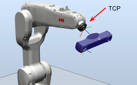
Calibration of the device on a moving robot arm allows determining the exact position of the device mounted on the moving robot arm with regards to the tool center point (TCP) of the robot. The calculation is done based on several scans of the marker pattern in different positions of the robot (its TCP). Knowledge of the exact position of the device on the robot is necessary to transform the position of the scanned object into the coordinate space of the robot.
Marker space allows finding the transformation between the tool center point of the robot and the fixed position of the device on the robot arm.
How do I find out if my point cloud is in the Marker space?
On the right side of the Viewer Pane in the Coordinates menu check the Axis box. This displays the axes of the point cloud coordinate system. Marker space axes can be easily visually checked in a 3D viewer to see if they are set correctly.
Scan in Marker space with displayed axes. Note: On newer marker patterns the axes origin will be in the origin of the axes printed on the marker patten in the corner.
Point cloud is not generated, and the status bar shows Error: Marker pattern was not recognized (3D-Based)!.
The marker pattern is not detected correctly. Either:
The visible portion of the marker pattern is too small
There are only collinear circles in the visible portion of the marker pattern
The angle between the marker pattern and the device is too big (please refer to Table 3, Table 4 and Figure 13),
The point cloud is in half resolution.
If using MotionCam-3D, the Operation mode is set to Camera
The point of origin of Marker Space is not in the center of the circle.
Check if the marker pattern is printed correctly without scaling or fitting it to paper. When the pattern is scaled the size of the circles is different, and the position of the point of origin is not calculated correctly.
Always use marker patterns available in PhoXi Control or downloaded from our website.
Does the origin point of Marker Space have to be visible to the device?
No. All the circles are unique so the origin point is calculated based on the circles that are visible.