Sensor Alignment Tool
This tool is a command-line application designed for the spatial alignment of multiple Photoneo 3D Sensors. It calculates and applies the spatial transformations to align two or more scanners into a single, shared coordinate system.
The alignment tool also supports chaining transformations through intermediate devices. This enables alignment even when not all devices have direct overlap with the master device, as long as there is a chain of overlapping observations. In all methods, one scanner is designated as the master device (the first in the device list).
Alignment Methods
There are four alignment methods available.
Texture-Based: Relies on identifying and matching common 2D features in the textures of the scans.
Sphere-Based: Uses at least three spheres of a known diameter placed in the scene. The application automatically detects these spheres and uses their 3D positions to compute the transformation.
Multi-Marker: An interactive method that uses a marker board to collect multiple marker positions across different placements. The user moves/rotates the marker board to multiple positions, capturing marker detections from all devices at each capture. The alignment is computed from the captured marker poses.
Marker-Dot: Uses the device’s built-in marker dot recognition to detect marker dots placed in the scene. The 3D positions of the detected dots are used to compute the alignment transformation. Requires at least three marker dots visible to all devices.
General Alignment Workflow
This workflow applies to all alignment methods. The specific actions required for your chosen method are detailed in the console and in the “Method-Specific Preparations” section below.
- Launch the Tool: In the Network Discovery window, select the primary (master) device and navigate to Utils > Sensor Alignment Tool.

- Select Devices: A command-line application will open. Follow the prompts to select one or more secondary devices.
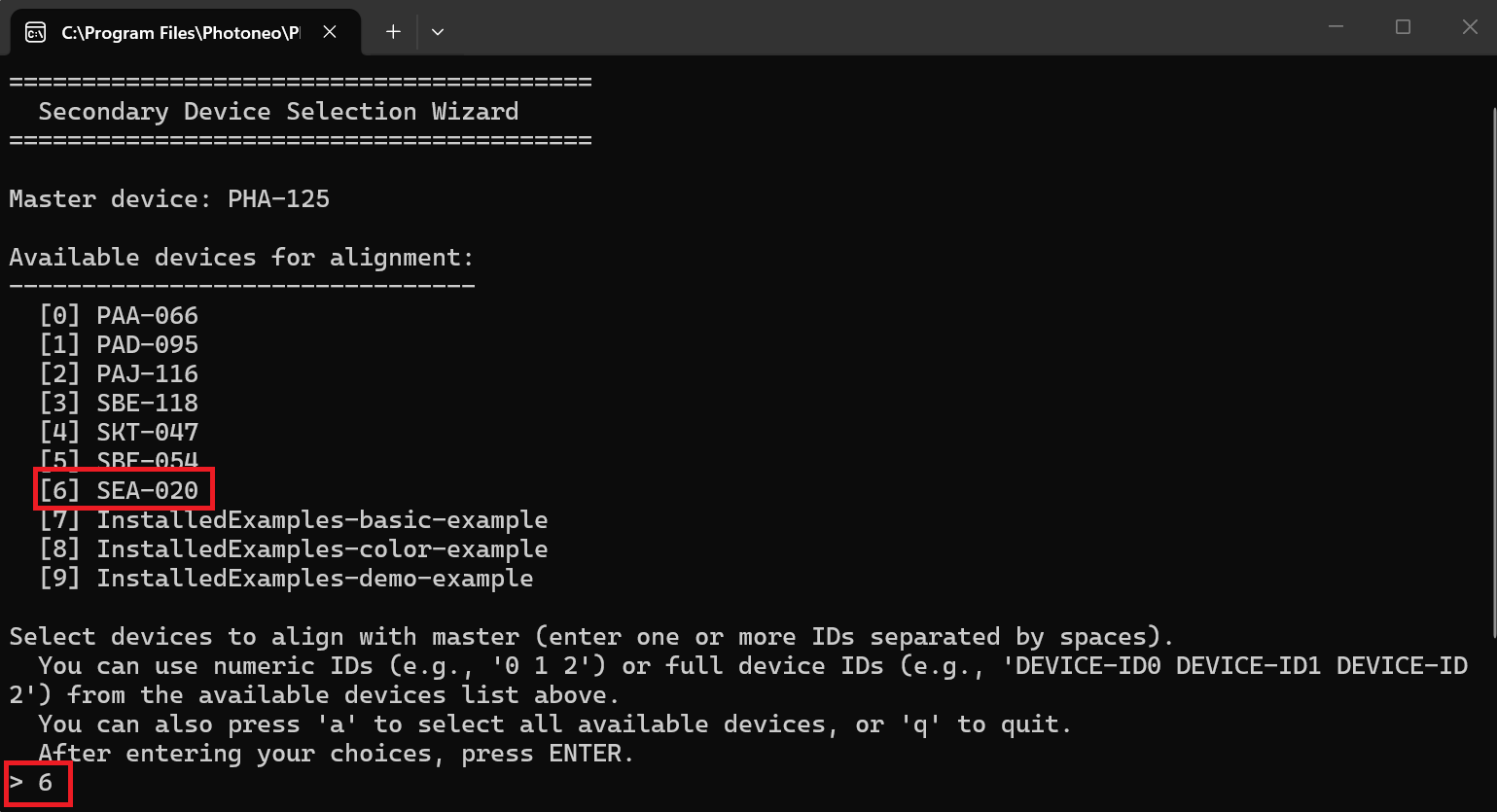
- Choose Alignment Mode: Select the alignment method you wish to use (e.g.,
Texture-Based,Sphere-Based, etc.).
- Set Coordinate Space: Decide if you want the tool to automatically set the coordinate space to
CustomSpaceafter a successful alignment.
- Configure Profile Settings: Choose whether to save the resulting alignment to a specific scanning profile.

- Follow On-Screen Instructions: The console will now provide specific instructions based on the chosen alignment method. This may involve moving objects, capturing scans, or entering data.
- Review Results: Once the process is complete, the application closes. If you choose to do so in Step 4, the transformation is automatically applied to the secondary devices. All scanners will now operate in the master device’s coordinate space.

Method-Specific Preparations and Instructions
Before starting the general workflow, prepare your physical setup according to the method you plan to use. During the workflow (Step 6), the console will guide you through the unique actions required for each method.
Method 1: Texture-Based
- Setup: Ensure the scanners have an overlapping field of view. Place at least one flat, texture-rich object (like an open magazine or a detailed poster) within the shared area to ensure a high-contrast, non-repetitive texture. This significantly improves the likelihood of a successful alignment.

Method 2: Sphere-Based
- Setup: Place at least three alignment spheres of the same, known diameter into the scene so they are visible to all scanners. The spheres should not form an equilateral or isosceles triangle; ensure that each pair of spheres in the triplet has a different distance between them.

- In-Tool Action: When prompted by the console, you will need to enter the diameter of the spheres in millimeters.
Method 3: Multi-Marker
- Setup: Have a marker board ready. During capture, the marker board must be detectable by at least two scanners at a time.
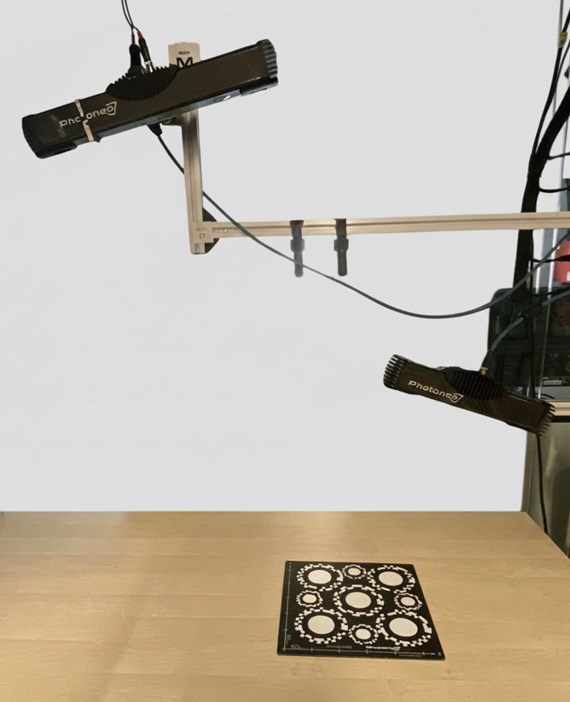
- Interactive Data Collection: The application will prompt you to place the marker board in different positions:
Place the marker board so it is visible to at least two scanners
Follow instructions shown in the console to capture scans from all devices
Move or rotate the marker board to a new position and repeat (more positions improve accuracy)
Only scan batches where at least 2 devices detect the marker are recorded
The tool reports which devices can be aligned with master after each scan batch and guides which devices still need more shared marker board captures
Method 4: Marker-Dot
- Setup: Place at least three marker dots in the scene so that they are visible to all scanners you wish to align. The dots should be well-distributed in 3D space (not collinear).

Standalone Application
Note
The paths below assume the default installation directory and version 1.17.0. If you installed PhoXi Control in a different location or are using a different version, please adjust the paths accordingly.
- Application: SensorAlignmentTool.exePath:
C:\\Program Files\\Photoneo\\PhoXiControl-1.17.0\\bin\\SensorAlignmentTool\\SensorAlignmentTool.exe - Instructions: README.mdPath:
C:\\Program Files\\Photoneo\\PhoXiControl-1.17.0\\bin\\SensorAlignmentTool\\README.md
- Application: SensorAlignmentToolPath:
/opt/Photoneo/PhoXiControl-1.17.0/bin/SensorAlignmentTool/SensorAlignmentTool - Instructions: README.mdPath:
/opt/Photoneo/PhoXiControl-1.17.0/bin/SensorAlignmentTool/README.md
Note
If you are using a different version of PhoXi Control, replace 1.17.0 in the paths above with your installed version.
Sensor Alignment Tool Configuration
While it is not typically necessary, you can adjust several parameters for the Sensor Alignment Tool by editing the config.txt file.
Both the configuration file and a detailed guide are located in the SensorAlignmentTool directory within the PhoXi Control installation folder.
config.txtPath:
C:\\Program Files\\Photoneo\\PhoXiControl-1.17.0\\bin\\SensorAlignmentTool\\config.txtThis file contains the adjustable parameters.
README.mdPath:
C:\\Program Files\\Photoneo\\PhoXiControl-1.17.0\\bin\\SensorAlignmentTool\\README.mdThe Configuration section of this guide explains how to use the config.txt file.
config.txtPath:
/opt/Photoneo/PhoXiControl-1.17.0/bin/SensorAlignmentTool/config.txtThis file contains the adjustable parameters.
README.mdPath:
/opt/Photoneo/PhoXiControl-1.17.0/bin/SensorAlignmentTool/README.mdThe Configuration section of this guide explains how to use the config.txt file.