3D Meshing
 Introduction
3D Meshing is a Windows-based application for automatic mesh creation from scans acquired by Photoneo scanning devices. Providing both a graphical user interface and API environment, it is able to perform scan acquisition, point cloud alignment and filtering, and surface reconstruction. The whole mesh-creating pipeline can be carried out as a one-click solution or in a step-by-step mode where each action is controlled by the user.
The application supports surface reconstruction on an automatic rotary table or in manual mode using marker patterns. The application supports the use of multiple Photoneo 3D scanning devices and allows the export of the reconstructed surface into PLY, STL, COGS, and FBX formats.
Custom/manual with marker pattern |
With automatic rotary table |
On robotic arm/handheld |
|---|---|---|
|
|
|


Getting Started
Before you start creating your own models, follow these steps:
Download and install 3D Meshing and PhoXi Control 1.10 or newer from our website.
Windows: Double-click the downloaded *.exe file to start the installation.
Linux: Use command dpkg -i <downloaded-package-file>.deb
USB sentinel key or trial license provided by Photoneo according to the Licensing section.
A computer meeting the minimum or recommended system requirements (see the System Requirements)
Marker patterns printed without any scaling. Marker patterns are available in PhoXi Control in Menu → Tools → Marker Pattern or on the website in the Marker Patter subsection.
Optional: Automatic rotary table provided by Photoneo or arbitrary rotary table controller with a predefined interface.
Please, contact us via the Help Center for licensing details and available accessories.
Besides this manual, it is strongly recommended to read the PhoXi Control User Manual
Licensing
Sentinel licensing software is installed automatically during the installation of 3D Meshing. In order to run the 3D Instant Meshing or use the library, it is required to have
A USB dongle connected to the device at all times (Sentinel software to recognize the USB dongle is installed automatically with 3D Instant Meshing)
A trial license provided by Photoneo. Request a free trial at https://www.photoneo.com/p3dm-license. 3D Instant Meshing must be already installed on the computer in order to request the license since the Sentinel licensing software (responsible for creating the c2v fingerprint file) is a part of the installation.
Refer to the Licensing guide if necessary.
Computer Requirements
The following is the recommended PC setup for 3D Meshing:
Disk |
SSD disk |
|---|---|
RAM |
16 GB or better |
Processor |
Intel i7 7700k or better
AMD Ryzen 1600 or better
|
GPU |
Nvidia GTX 1060 or better |
OS |
Windows 10 64-bit
Ubuntu 18
|
Multiple Versions of PhoXi Control
Multiple versions of 3D Meshing can be installed on one computer. This is achieved by choosing different installation directories during the installation. The process is as follows:
Windows
On Windows, the installer asks for a path where the application should be installed. By default, this path is
C:\Program Files\Photoneo\PhoXi3DMeshing\<version>
When another version of 3D Meshing is installed, a different path should be specified, for example,
C:\Program Files\Photoneo\PhoXi3DMeshing\<version>-custom
User Directory (configuration, temporary, and log files)
C:/Users/AppData/Local/PhoXi3DMeshing/<Version>/
Linux
Ubuntu installer automatically installs 3D Meshing in the following folder:
/opt/Photoneo/PhoXi3DMeshing
User Directory (configuration, temporary, and log files)
/home/.config/PhoXi3DMeshing/<Version>/
GUI Overview

Device setup menu
Scans and models menu
3D Model pipeline menu
Viewport
Visualization menu
Device Setup
The device setup menu is accessed by the Setup devices button in the device menu (1.). It allows the user to connect to the scanner(s), choose between manual and automatic mode, and calibrate the devices together.
The device setup menu also displays the ID(s) of the connected scanners and allows users to control the number of turns of the automatic rotary table (if available).
Manual Mode
In manual mode, the object is placed on the marker pattern which allows pre-alignment of the scans necessary for complete surface reconstruction. Marker pattern can be used with or without a manual rotary table with an arbitrary number of Photoneo 3D Sensors. The number of scanners directly affects how the calibration procedure is handled.
One Photoneo 3D Sensor

The marker plate has to be present and recognizable in all scans. It is recommended to place the marker plate directly below the scanned object and make sure it is at least partly visible to the scanner from all angles.
Select the primary device from the Primary device drop-down menu to connect to it.
Click Done to proceed to scan the acquisition.
Multiple Photoneo 3D Sensors

When multiple scanners are used in manual mode, they have to be calibrated with each other before the scans are acquired. The calibration is achieved with the marker plate. The principle of the calibration is that a scan of the marker pattern provides information about the relative positions of the scanner with regard to each other.
The full process to calibrate the scanners together is the following:
Connect to the primary scanner by selecting its ID from the Primary device drop-down menu.
Enter the secondary devices menu using the Setup secondary device button.
Select the scanner ID from the drop-down menu.
Place the marker plate in a place visible for both the primary and the secondary scanner.
Use Calibrate using a marker board to calibrate the secondary scanner with the primary scanner.
To set up more than one secondary device, use the Add device button and select its ID from the drop-down menu.
Place the marker board in a place where it is visible by the primary scanner and the device that is currently being calibrated. Use Calibrate using a marker board to calibrate the devices together.
The calibration needs to be repeated again if the position of the calibrated devices changes in any way.
A marker plate has to be present during the scanning, but it only needs to be visible by the primary scanner.
Automatic Mode
Automatic mode is designated for 3D model creation using an automatic rotary table controlled from within the application. To switch the application to the automatic mode, tick the Using automatic rotary table checkbox.
For correct functioning, the application requires a USB serial port for a connected rotary table. The green tick next to the USB serial port indicates that the rotary table has been recognized correctly. If there is no green tick, try to determine the number of the serial port using the Device Manager. One or multiple Photoneo 3D Sensors can be used to capture scans on the rotary table.
One Scanner

Calibration is needed to use the application with the automatic rotary table. A marker plate is necessary for calibration but can be removed from the scene after it is finished. To calibrate the scanner with an automatic rotary table:
Select the primary scanner from the Primary device drop-down menu.
Select the USB-connected table for the integrated rotary devices or the name of the device you have integrated yourself.
Place the marker pattern on the rotary table.
Use the Calibrate button to calibrate the primary scanner with the rotary table. The scanner will make scans of the marker plate from several positions of the rotary table.
After the calibration is finished, click Done and proceed to capture scans.
Multiple Scanners
Using multiple scanners with the automatic rotary table requires calibration as well. This is a two-step process in which first the automatic rotary table is calibrated with the scanner and second the scanners are calibrated with each other. To calibrate multiple scanners with the rotary table, the following steps are necessary:
Connect to the primary scanner from the Primary device drop-down menu.
Place the marker plate on the rotary table.
Use the Calibrate button to start the calibration. It works the same way as if there was only one scanner in use.
Once the calibration is finished, use the Setup secondary devices button to connect to the secondary scanner.
Select the device ID from the secondary device drop-down.
Place the marker plate in a place where it is visible by the primary scanner and the scanner that is currently being calibrated.
Use the Calibrate using a marker plate to start the calibration. The scanners will each capture a scan of the marker plate.
Click Done to proceed to scan the acquisition.
Once the calibration is finished, the marker plate does not have to be present in the scene during scanning.
Fixed Setup

If the scanner is in a fixed setup with the rotary table - the relative position of the scanner with regards to the platform of the rotary table does not change - it is not necessary to perform the calibration every time the application is opened. 3D Meshing can automatically connect to the last known scanner and use the last known calibration. This setting is enabled in Settings by ticking the Load last calibration on startup checkbox.
One-Click Solution

To run the whole pipeline of model creation, use the Create 3D model button. This runs through all of the steps of the pipeline:
Scan capturing
Scan alignment
Scan filtering
Surface reconstruction
Surface trimming
Running the one-click solution in automatic mode runs the whole pipeline without any other input from the user. In the manual mode, it is necessary to acquire the scans from different points of view. This means that the user either needs to change the position of the scanner or perform rotations of the manual rotary table.

Step-by-Step Solution

Capturing Scans
To have full control of the model-creating pipeline, go to Settings and tick the Advanced mode checkbox.
Use the Capture scan in the model generation menu to trigger a scan on the Photoneo 3D Sensor(s). In manual mode, this will trigger a scan from all connected devices. In automatic mode, it will trigger scans and perform rotations of the rotary table to capture the mode thel specified amount of times.
The application displays each point cloud in a different color for easier orientation. Once you are satisfied with the scans you can proceed with model creation. If you wish to eliminate any scan from the pipeline, simply deselect it in the scans menu.

The result after the capturing phase is pre-aligned point clouds of the object:

To achieve the best possible scans, set up appropriate scanning parameters in PhoXi Control. It is recommended to use scanners with firmware version 1.2.14 and higher in manual mode. The 3D ROI parameter allows the removal of the background from the scan. Background removal is handled automatically in the automatic mode.
Alignment
Alignment is the first step of the point cloud processing part of the pipeline. It uses a tailored proprietary ICP algorithm to reposition the point clouds in a way that the points representing the same spots are overlapping and not just neighboring. The result is point clouds transformed into a different position creating the best possible overlap of the points. The scans in 3D Meshing are already pre-aligned by the calibration process or by the marker pattern, therefore the fine alignment might not be easily noticeable but can be seen once the point clouds are zoomed in.
|
|
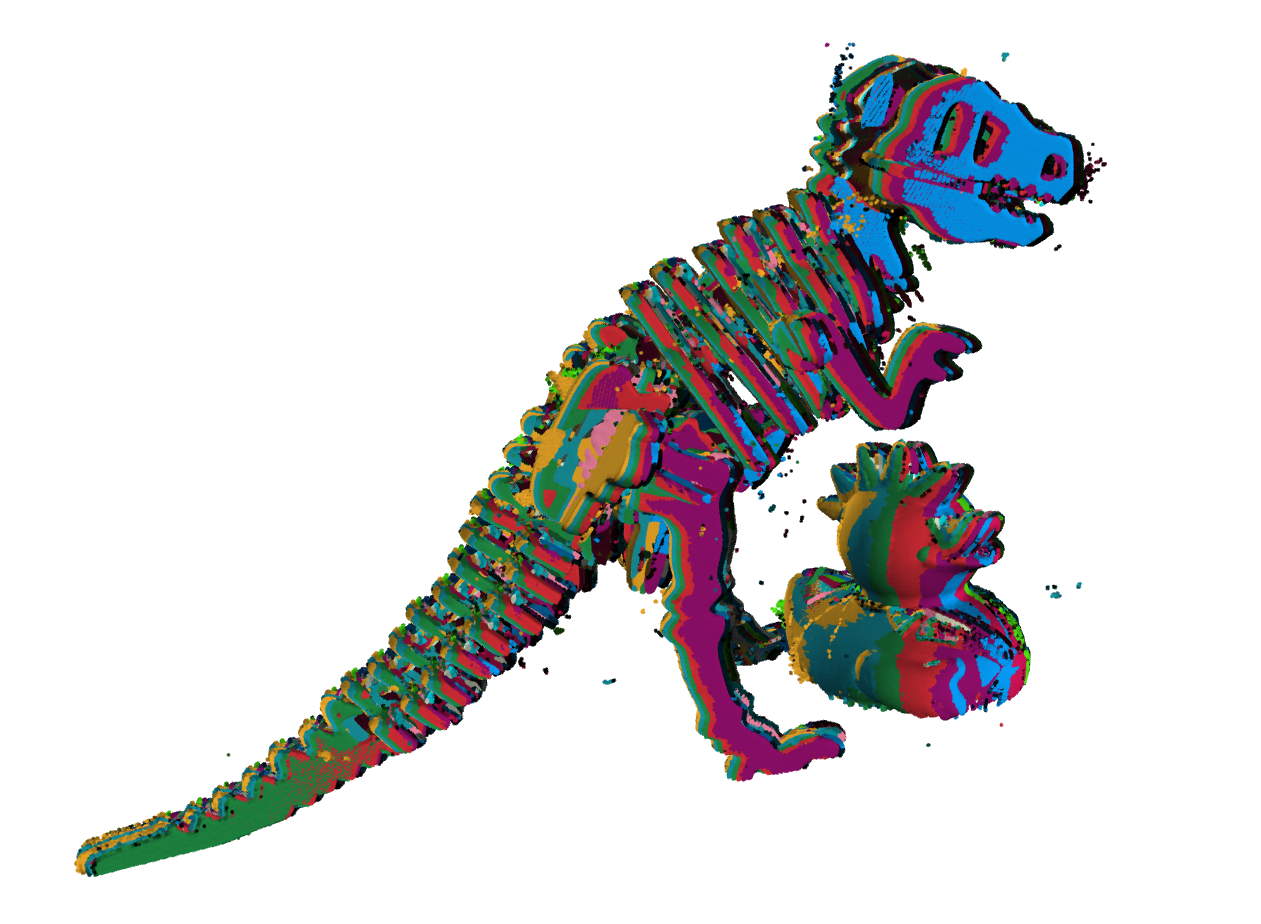
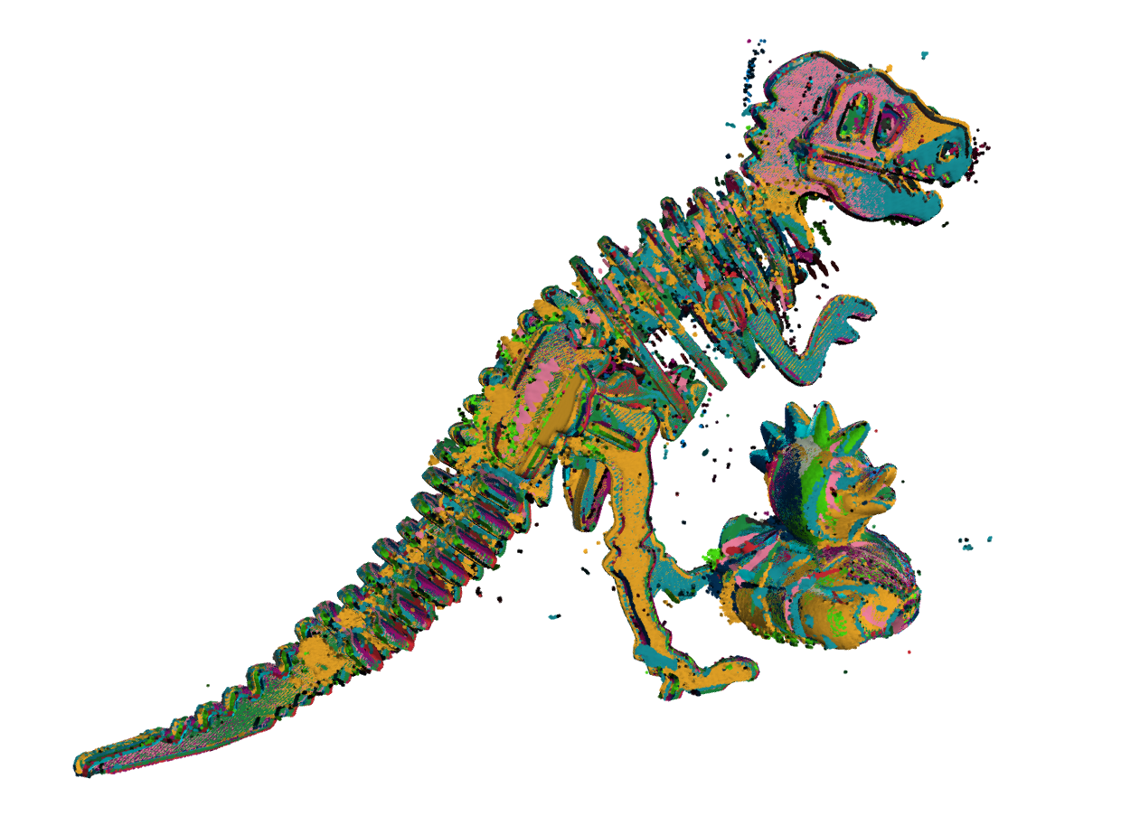
To run alignment on the captured scans, use the Align button. The pictures above demonstrate the point clouds before and after fine alignment.
Filtering
Filtering is a process where 3D points in one scan are compared with points in one or more neighboring scans. If any point from the reference scan can be found in the neighboring scans the point is kept in the point cloud. If the comparison scans do not confirm the point from the reference point cloud, the point is filtered out.
Filtering gets rid of points that are caused by reflection from glossy materials or represent areas that are not part of the surface of the scanned object.
To run filtering on the captured scans, use the Filter button.
|
|

Reconstruction
During the reconstruction, the point clouds are processed to create a finite number of polygons that represent the surface. To run reconstruction on the captured point cloud, use the Reconstruct button.
|
|
|
|


Surface Trimming
Surface reconstruction creates polygons even in places where the point cloud contains holes or on the edges of the model. These polygons are cut off using the trimming tool to create a model that is a more accurate representation of the object.
To run trimming on the reconstructed surface, use the Trim surface button.
|
|


Surface Detail
3D Meshing allows the user to control the level of detail of the reconstructed surfaces. There are three possible levels of detail controlled from within Settings. The setting controls the number of polygons created during the reconstruction process, therefore new reconstruction has to run for the setting to take effect. The higher level of detail leads to longer computation time.
Surface detail is controlled from the Model generation quality drop-down menu. The available settings are:
Speed
Balanced
Quality

Speed is the fastest, lowest surface detail setting, while Quality has a longer computation time but higher level of detail. Balanced is the compromise between computation time and level of detail.
The differences from the lowest level of detail to the highest can be observed in the images below.
|
|
|


Multiple Scan Sequences Mode
The Multiple Scan Sequences Mode allows the user to scan the object in multiple positions on the rotary table, leading to a full 360° model that does not miss any surfaces on the bottom of the object.
When the multiple scan sequence mode is enabled, the pipeline pauses after the first round of acquisition is finished. During this pause, the position of the object on the rotary table can be changed and the acquisition restarted. The number of acquired sequences is unlimited.

To enable Multiple Scan Sequences mode, open Setting and tick the Multiple Scan Sequences mode checkbox.
This mode works both with the one-click solution and the step-by-step solution.
In One-Click Solution
Usually in the one-click solution, the model creation pipeline in automatic mode does not require any inputs from the user. In the Multiples Sequences Mode, the pipeline pauses after the acquisition is finished (after the set rotations of the table) and gives the user the time to change the position of the object on the rotary table. During this pause, the 3D model pipeline menu on the top changes and displays the following buttons:
Capture new sequence
Generate model

Clicking the Capture new sequence button starts a new scanning sequence. The scanner and the rotary table are going to perform the number of scans selected in the Device setup menu. Then a localization algorithm is going to transform the set of scans from the second sequence to the coordination space of the first scan sequence. Once this is finished, the user can choose again how he wants to proceed.
The Generate model button will finish the acquisition and proceed with 3D model creation by aligning the scans, filtering them, and then reconstructing and trimming the surface.
In Step-by-Step Solution
The step-by-step solution offers the user full control over the model creation pipeline. The same is true in the Multiple Scan Sequences Mode. After clicking the Capture button, the application proceeds with the first scanning sequence. Once it is finished, the application waits for user input in the 3D model pipeline menu. If you wish to capture a new sequence, change the position of the object and click the Capture new sequence button. If you want to proceed with creating the model, click the Finish sequence button.
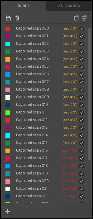
Each captured scan in the Scans menu is now also distinguished by the sequence it belongs to. Any scan can be disallowed from further processing by unticking its checkbox. To untick the whole sequence, double-click it.

Exporting
Exporting Scans
The scans can be exported after applying any step of the pipeline. If the scans are saved after capturing, the point cloud contains all 3D points as they were captured by the scanner. If the point clouds are processed by any of the pipeline tools they are saved as processed.
Supported formats to save the point clouds are PLY and COGS - the application-specific file format.
The export directory and naming convention can be specified in the saving dialog. All or selected scans can be saved separately or in a union point cloud.

Exporting Models
The reconstructed models can be saved both before and after trimming. The processing of the model done during the trimming phase is reflected in the saved model.
Supported formats to save created models are PLY, STL, OBJ, DAE, FBX, and COGS - the application-specific file format. The saving dialog allows the user to specify the saving directory, name convention and if only selected or all models should be saved.

Automatic Export

Models created by the Create 3D Model button can be saved automatically to a folder specified in Settings. Automatic export is enabled by a slider in the model generation menu. Models saved this way are in PLY format.

Importing
Importing Scans
To create a model, the scans do not have to be captured directly in the application. Import of point clouds in PRAW, PLY, and COGS formats is supported. However, if the scans are imported with the purpose of creating a surface model, they need to be pre-aligned. The pre-alignment can be achieved by making the scans in marker space.
The import is handled via the + button in the Scans menu.
Importing Models
Models can be imported into the application as well. The supported file format for importing models is COGS.
Import is handled via the + button in the Model menu tab.
Visualization
The orientation of the point cloud /models and the render style of the models can be changed using the buttons in the visualization menu.
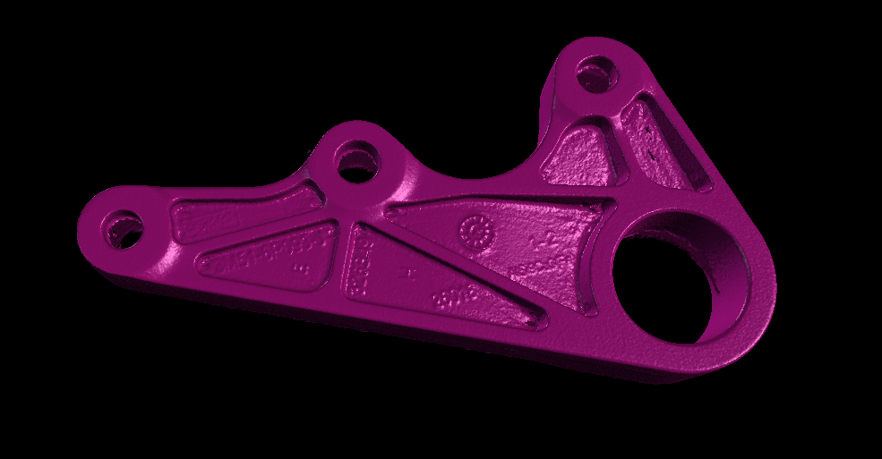
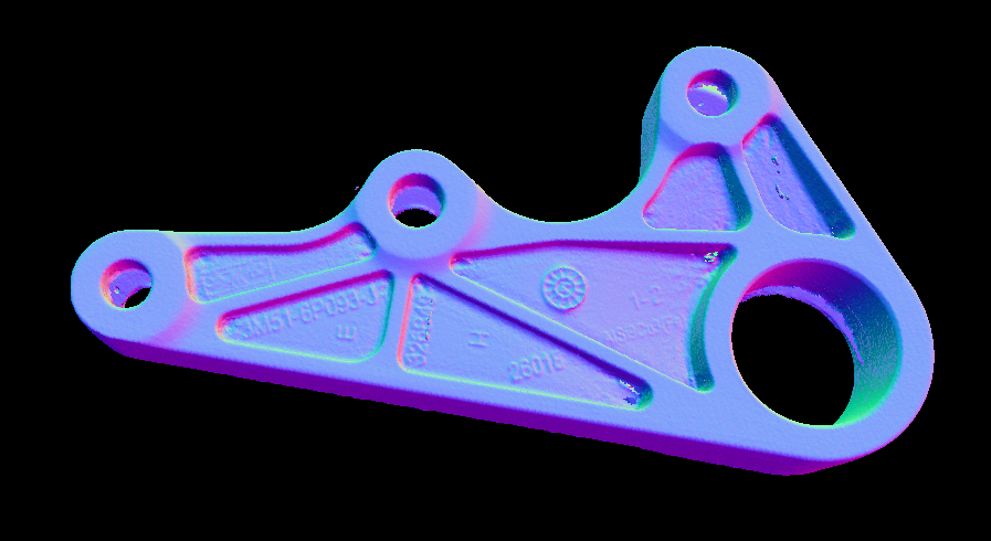
The render style of the generated model can be changed using the Render style button. There are seven different render styles:
Index color - based on the color assigned to the model in the 3D model menu
Texture - based on intensity data gathered during scan acquisition (Laser, Calculated, LED, Color)
Glaze
Metallic
Normals - based on the orientation of surface normals
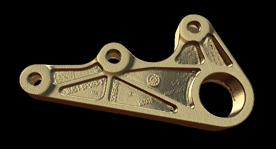
Golden
Plaster
|
|
|
|
|
|
|



The Axis button toggles on/off the visualization of the axis
The orientation of the point clouds or models can be changed by the buttons in the View group. The X-axis [X] and Y-axis [Y] change the orientation of the object so the axis in the description is aiming away from the user, and the Z-axis [Z] changes the orientation so that the axis aims toward the user. The Fit [Space] button resizes the object to fit the whole viewport. All the images below have the Fit space option on and are in the order X, Y, and Z.
|
|
|
|


API
3D Meshing API provides tools necessary to control the model-creating pipeline through C++ code. The API functionalities are showcased in several examples. You can start your own development based on the examples and modify them to suit your needs.
The examples are located on the following path:
C:\Program Files\Photoneo\PhoXi3DMeshing\<Version>\API\examples
Example name |
You will learn how to |
Automatic Mode |
|
Import Scans |
|
Manual Mode |
|
The full API documentation is available in the 3D Meshing API section.
To run the examples:
If you want to modify the code, it is recommended to copy the folder API with all of its subdirectories into your custom directory.
Launch CMake:
Choose the source and destination directory.
Click the Configure button, specify Visual Studio as the generator for the project, and confirm with the Finish button.

Wait until the configuration is completed, then click the Generate button.
Click the Open project button or open the file Main.sln in the destination directory.
Set the project P3DM_API_AutomaticMode as a StartUp Project in the right context menu.
Rebuild the solution in Visual Studio (Menu → Build → Rebuild Solution).
Make sure that the PhoXi Control application is running.
In Visual Studio, hit F5 to run the example (Menu → Debug → Start Debugging)
Rotary Device Integration
3D Meshing allows integration of arbitrary rotary tables and devices. To integrate your own rotary device you need to prepare a turntable plugin and copy it into
C:\Program Files\Photoneo\PhoXi3DMeshing\2.3.0\table-plugins
Turntable Plugins
Turntable plugin is an executable command-line application that is able to control the rotations of the device in the automatic mode. All files in the directory specified above are considered to be plugins, so make sure to generate EXE files without any auxiliary files that would unnecessarily clog the drop-down menu.
A turntable plugin accepts the following calls:
-status |
Executes connection validation.
Returns 0 when validation was successful or error bit flags otherwise.
-rotate ANGLE |
Rotates the table by a specified angle.
ANGLE is a floating-point number specifying the angle in degrees. Both positive and negative angle values are accepted.
Returns 0 when rotation finished successfully or error bit flags otherwise.
Troubleshooting
If the following section does not help in solving the difficulty you are experiencing, contact our support team contact us via Help Center with the log files attached which can be found at
C:\Users\<User>\AppData\Local\PhoXi3DMeshing\<Version>\logs
The more information you provide, the faster and more accurate the answer can be. Additionally, please describe what you have been trying to do, what the result was, and what you expected. Depending on the nature of the problem, please also report the version of the operating system being used, your PC configuration, and other additional information that would be helpful in replicating the problem and identifying its root cause.
Yes. It is important to observe scanning distances and keep in mind that the density of the point cloud and the level of detail are smaller with growing scanning distance.
The final number of points depends on:
the size and shape of the scanned object
scanning distance (smaller distance provides a higher density of points)
the scanner size
the number of captured scans and their overlap
The quality of the surface reconstruction and the number of created polygons can be configured between speed, balanced and quality. Example: In the final point cloud consisting of 5.18 million 3D points, Model Generation Quality set to Speed provides 0.89 million triangles, while Quality setting results in 4 million triangles of the final model.
Yes, Ubuntu 18.
No, for editing there are several free or open-source applications recommended for this purpose: Meshlab, and CloudCompare. For inspections, there are applications like PolyWorks Inspector or similar.
The 3D Meshing version currently integrates ComXim and Standa (www.standa.it/) rotary tables
Other arbitrary rotary devices can be integrated by the user by supplying a turntable plugin to 3D Meshing.
To remove the background from the scan in manual mode, please use the appropriate 3D ROI cutting in PhoXi Control. Only devices with firmware version 1.2 and higher can set up the 3D ROI. Refer to the PhoXi Control User Manual.
Alternatively, set the appropriate 3D ROI in
C:\Users\<User>\AppData\Local\PhoXi3DMeshing\<Version>\config\config.txt
using the aabb_min and aabb_max parameters. All values are in
millimeters.
aabb_min = -200 -200.0 2.0
aabb_max = 200.0 200.0 400.0

First, try to remove the paper with the marker pattern from below the
object. If the problem persists, open config.txt in the
C:\Users\<User>\AppData\Local\PhoXi3DMeshing\<Version>\config
folder, delete the # from before the
#aabb_min = -200 -200.0 2.0
#aabb_max = 200.0 200.0 400.0
If this does not help, change the last of the 3 numbers in the #aabb_min = -200 -200.0 2.0 to a higher value. The same effect can be observed when increasing the value of ground_offset in config_prafos.txt in the same folder. This is the offset from the pad of the rotary table and it is in millimeters.
Yes, the API allows specifying the coordinate system (transformation) for each scan. In order to use a Photoneo 3D Sensor mounted on a robot, for each scan, it is necessary to specify the position of the robot arm at the time of taking the scan. Calibration of the scanner coordinate system with the robot is necessary. Consult Help Center for more instructions specific to your use case.
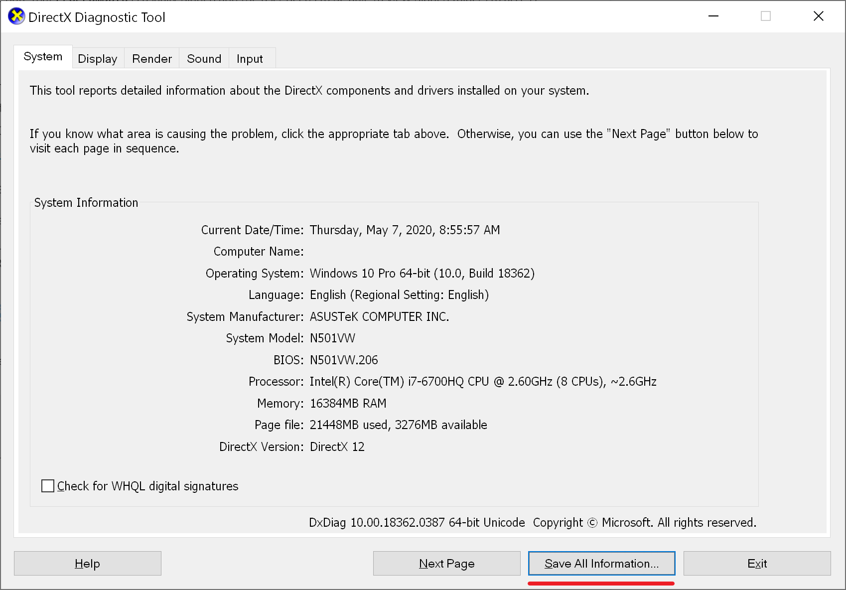
Please press Winkey + R and type “dxdiag”:

This will open the DirectX Diagnostic Tool. Please hit Save All Information… and send us the text file together with the description of your problem to the Help Center.

Zebra Technologies Slovakia s.r.o.
Plynárenská 6
821 09 Bratislava
Slovakia
Copyright and Legal Notice
User Manual for 3D Meshing 2.3.0
Document version: 10/2025
All rights reserved.
No part of this publication may be reproduced, stored in a retrieval system, or transmitted in any form or by any means, electronic, mechanical, photocopying, recording, or otherwise, without prior written permission of the publisher.
Copyright © 2014-2024 by Photoneo s.r.o., Bratislava, Slovakia
Copyright © 2025 by Zebra Technologies Slovakia s.r.o., Bratislava, Slovakia
Photoneo®, PhoXi® Control, PhoXi® 3D Scanner, and PhoXi® 3D Meshing are registered trademarks of Zebra Technologies Slovakia s.r.o.
Microsoft, Windows, Windows 10, and Visual Studio C++ are either trademarks or registered trademarks of Microsoft Corporation.
Linux is a trademark of Linus Torvalds.
All other nationally and internationally recognized trademarks and trade names are hereby recognized.
Powered by Skeletex Research.