3D Instant Meshing
 Introduction
3D Instant Meshing is a C++ library for real-time tracking and integration of 3D scans into a triangular mesh. The library works only with Photoneo’s scanning devices. The library is meant to be integrated into arbitrary applications by the user. For requests on complete solutions, e.g. integration of the library with robotic manipulators, rotary tables, linear axis, or any other setups, please, contact Photoneo.
The 3D model is created by moving a Photoneo 3D sensor around an object or scene and capturing it from multiple perspectives. The device can be moved by hand or by a robot manipulator in arbitrary motion. For a scene with enough 3D features (not a planar scene), the process of creating a 3D model does not require any additional information about the position of the 3D camera. For planar objects, the position of the camera can be supplied to the library.
The library comes with a simple Graphical User Interface that demonstrates the use of the library. The data can be exported in *.ply, *.obj, and *.off file formats.
Getting Started
Before you start creating your own models, follow these steps:
Download and install 3D Instant Meshing and PhoXi Control 1.10 or newer from our website.
Windows: Double-click the downloaded *.exe file to start the installation.
Linux: Use command dpkg -i <downloaded-package-file>.deb
A computer meeting the minimum or recommended system requirements (see the System Requirements section)
USB sentinel key or trial license provided by Photoneo according to the Licensing section.
A computer meeting the minimum or recommended system requirements (see the System Requirements)
Optionally:
Marker patterns printed without any scaling. Marker patterns are available in PhoXi Control in Menu → Tools → Marker Pattern or at photoneo.com
A rotary table provided by Photoneo or an arbitrary rotary table controller
Please contact us via Help Center for licensing details and available accessories.
Besides this manual, it is strongly recommended to read the PhoXi Control User Manual
Licensing
Sentinel licensing software is installed automatically during the installation of 3D Meshing (Install Sentinel checkbox must be selected). In order to run the 3D Instant Meshing or use the library, it is required to have
A USB dongle connected to the device at all times (Sentinel software to recognize the USB dongle is installed automatically with 3D Meshing)
A trial license provided by Photoneo. Request a free trial at https://www.photoneo.com/p3dm-license. 3D Meshing must be already installed on the computer in order to request the license since the Sentinel licensing software (responsible for creating the c2v fingerprint file) is a part of the installation.
Refer to the Licensing guide if necessary.
System requirements
Minimum |
Recommended |
Intel i5 (gen 7) / AMD Ryzen 5 (gen 1) |
Intel i7 (gen 7) / AMD Ryzen 7 (gen 1) or better |
8GB RAM |
16GB RAM or more |
NVIDIA GTX 10xx series GPU with compute capability 6.1 and 3GB VRAM |
NVIDIA GTX 2060 series GPU or better with at least 6GB VRAM |
OS Win 10 64-bit or Ubuntu 18.04 64-bit |
OS Win 10 64-bit or Ubuntu 18.04 64-bit |
NVIDIA driver 531.68 (Windows)/515.65.01 (Ubuntu) |
NVIDIA driver 531.68 (Windows)/525.105.17 (Ubuntu) |
Photoneo PhoXi Control 1.10 |
Photoneo PhoXi Control 1.10 or newer |
Multiple Versions of PhoXi Control
Multiple versions of 3D Instant Meshing can be installed on one computer. This is achieved by choosing different installation directories during the installation. The process is as follows:
Windows
On Windows, the installer asks for a path where the application should be installed. By default, this path is
C:\Program Files\Photoneo\PhoXiInstantMeshing\<version>
When another version of 3D Instant Meshing is installed, a different path should be specified, for example,
C:\Program Files\Photoneo\PhoXiInstantMeshing\<version>-custom
User Directory (configuration, temporary, and log files)
C:/Users/AppData/Local/PhoXiInstantMeshing/<Version>/
Linux
Ubuntu installer automatically installs 3D Instant Meshing in the following folder:
/opt/Photoneo/PhoXiInstantMeshing
User Directory (configuration, temporary, and log files)
/home/.config/PhoXiInstantMeshing/<Version>/
GUI overview
Graphical User Interface serves for evaluation of the library performance, creating and exporting of 3D models. It uses the PhoXi Control API to connect to the Photoneo 3D sensors and provides scans directly to the library.
Device setup
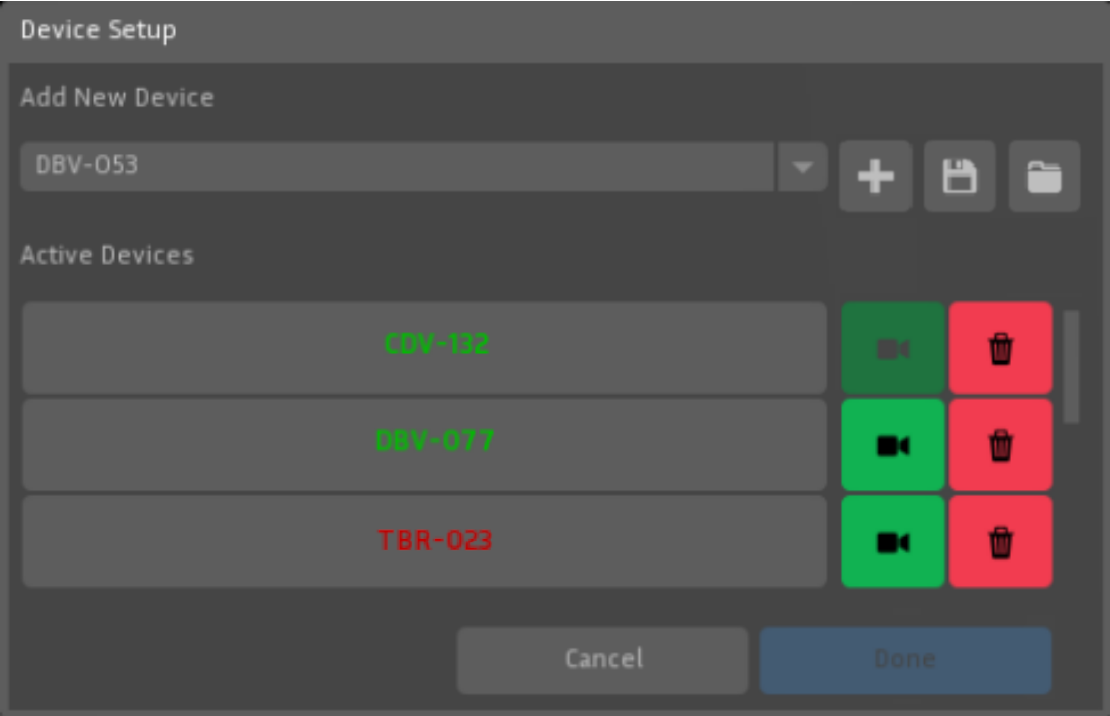
After launching the 3D Instant Meshing, the Device Setup menu is displayed.
Choose the device from the list (PhoXi Control needs to be running) and hit the plus icon. The device will then be displayed in the Active Devices section. To remove the device from the Active devices, use the red trash bin icon.
With automatic rotary table |
On robotic arm/handheld |
Gantry setup with multiple devices |
|---|---|---|
|
|
|


Multiple device calibration
It is possible to connect to multiple devices at once. In order to use multiple devices, a marker pattern needs to be used to calibrate the devices into one coordinate space. The calibration will be performed automatically, however, the marker needs to be visible by all sensors simultaneously. Using the floppy disk icon, you are able to save your existing calibration in a form of a *.json file. Use the folder icon to load existing *.json calibration (devices will be picked automatically based on the *.json configuration file).
Note: Instant Meshing automatically uses LED texture for all the devices during the calibration process. If the ambient light is not sufficient, it might be necessary to increase the LED power. Additionally, it is recommended to update the device to firmware version 1.10.0 which improved the marker board recognition significantly. Find out more at https://www.photoneo.com/downloads/firmware/.
|
|






Adding devices is also possible in the Control pane by clicking the Setup Devices button and it does not have to be done only at the launch of 3D Instant Meshing.
Note: Marker patterns can be found at
C:\Program Files\Photoneo\PhoXiControl<version>\MarkerPatterns or at
photoneo.com
In order for multiple devices to be running at the same time, it is recommended that the devices are triggered sequentially, so their projections do not overlap (possible point cloud distortions). The user has 2 options:
Uncheck the Enable Freerun checkbox which means, that the devices are triggered by a software trigger and not running in freerun. This option lowers the framerate.
Use the hardware trigger to acquire data from multiple devices. if the Photoneo 3D Sensors are configured in a Hardware trigger mode, the Enable freerun checkbox needs to be selected. For more detailed information about the software side and topologies refer to the PhoXi Control User Manual. To find out more about the wiring and hardware requirements, refer to the Photoneo 3D Sensor User Manual.
Overview
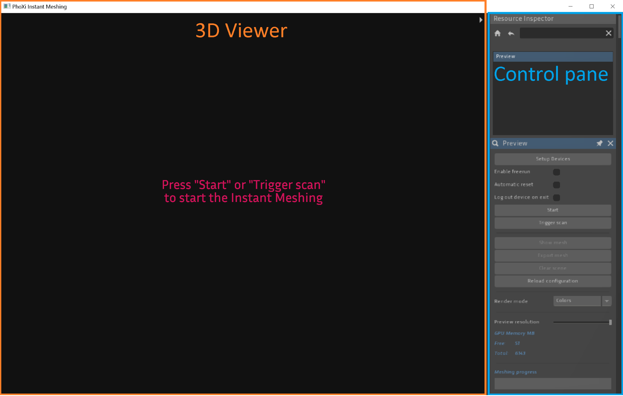
The application UI consists of the following parts:
3D Viewer
3D Viewer can be maximized using the gray arrow in the top right corner of the 3D Viewer
It can be used to display the actual preview of the meshing process or to display a mesh
Control pane
Resource inspector (displayed at the start)
- Global settings

- Camera Animator

Resource inspector

After launching the 3D Instant Meshing, Resource Inspector will contain only a Preview. Additionally, after creating a mesh, Mesh will appear in the list.
Preview controls
Setup Devices |
Opens up a Device setup menu to add or remove active devices |
|
Enable Freerun |
Uses freerun acquisition |
|
Automatic reset |
Automatically resets the meshing sequence at Tracking lost |
|
Log out device on exit |
After closing 3D Instant meshing, the device will be disconnected in PhoXi Control |
|
Start |
Start the acquisition |
|
Trigger scan |
Triggers only an individual scan |
|
Show mesh |
Shows a rendered mesh in the Mesh window |
|
Export mesh |
Exports the mesh in a *.ply, *.obj, or *.off file |
|
Clear scene |
Deletes the previous scans in the Preview window |
|
Render mode |
Colors - uses the Color texture source Normals - uses the Normals Grey - uses the Laser Color texture source |
|
Preview resolution |
Adjusts the resolution in the preview window |
|
GPU memory |
Displays the Total and Free GPU memory |

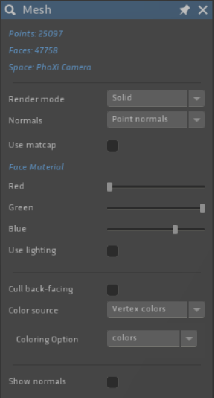
When a mesh is shown, the Mesh window offers the following rendering options:
|
|
Global settings
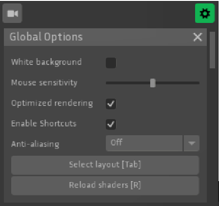
This gadget can be displayed by clicking the icon, which will
change to  when activated.
|
|
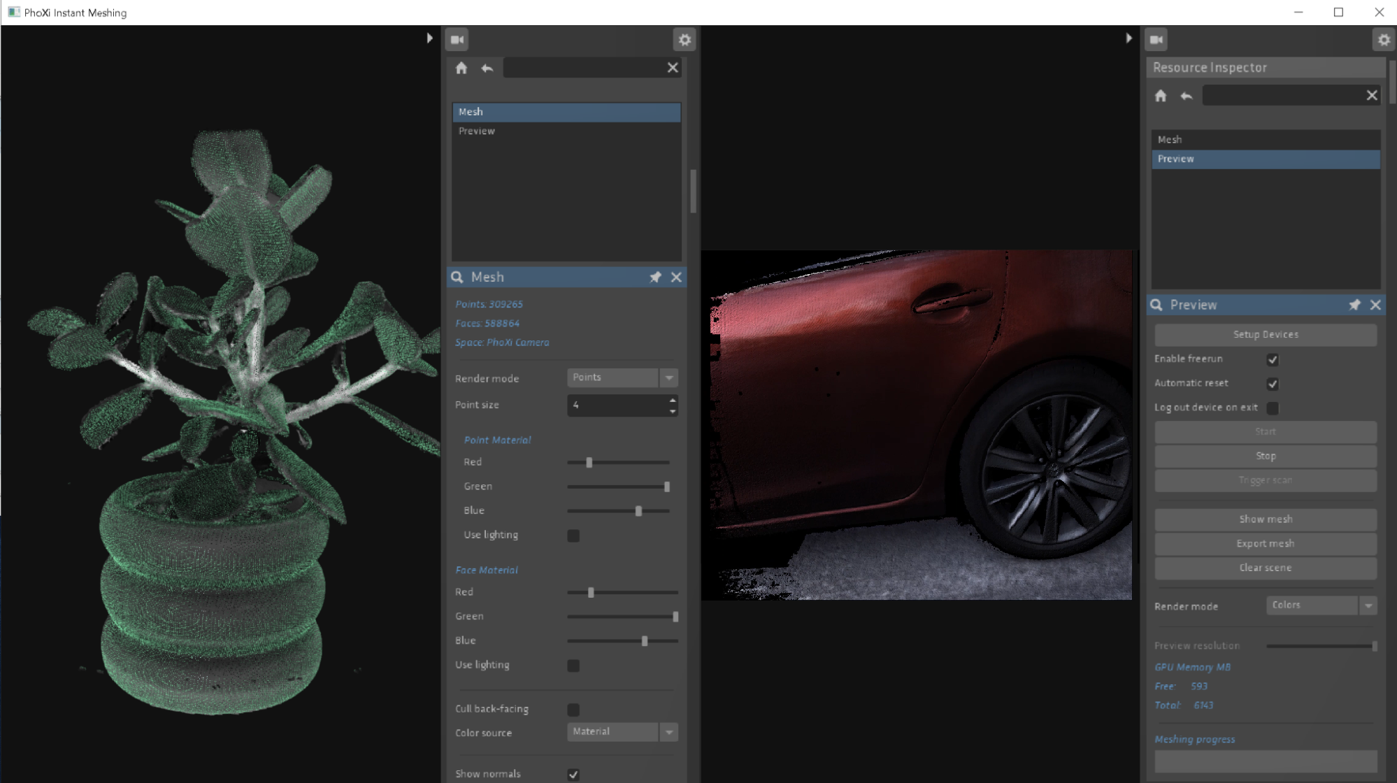
Select layout option allows the user to split the UI up into 4 areas. Each area can display different information. The following figure shows a split-screen mode where the left side shows the finalized mesh and the right side displays the actual meshing process.
GUI Keyboard shortcuts
F11 - Fullscreen toggle
TAB - Change UI layout
Right mouse click on viewport - Scene options
Home - Reset view (the magnifying glass button)
E - Export mesh
R - Reload config
SPACE - Start/stop stream
T - Trigger the next frame
X - Clear scene
1 - Vertex colors
2 - Normals
3 - Gray
Meshing guide
Operation Principle
3D Instant Meshing is designed as a library for real-time tracking and integration of 3D scans into a triangular mesh and it is independent of the data source (Photoneo 3D Sensor). As an input, it expects a sequence of scans of the scene that differ only slightly (small perspective change), so the library can track the movement of the camera relative to the scene, and add new scans to an existing model. The basic coordinate system of the model is defined by the first scan or can be arbitrarily changed.
Tracking Performance
Tracking is the ability of the library to recognize the movement between the 3D camera and the scene so that the newly acquired scan from the new perspective can be added to the existing 3D model.
The tracking performance relies on
Geometrical features of the scene
2D features (if texture tracking is enabled).
The more distinguishable features the object has, the easier it is to match the individual scans, and therefore it is less probable that the tracking is lost. The sensitivity of tracking can be adjusted. Highly sensitive setting requires very small movements, less sensitive allows for larger movements, but can also introduce incorrect alignment of the scans.
In the case of a mostly planar scene or a scene that does not consist of enough features, the algorithm can partially rely on 2D tracking, however, it is possible to override the tracking (/partially/completely) by providing a transformation matrix for each scan. This could be useful, for example, if a robotic arm with very precise position reporting is used. Two or multiple cameras which are calibrated in the same space can contribute to the same model.
Retrieving the Data
The library creates a data representation of the 3D model which can be retrieved in the form of a 3D surface model at any time. The finalized mesh can be exported in *.ply, *.obj, or *.off formats. The size of the 3D model, as well as the processing time, depends on several factors, such as the scanning volume of the device, ROI, the voxel size or the size of the scanned area. Additionally, the user can export a virtual 3D scan of the 3D model from an arbitrary view.
Quality of the 3D Model and Performance
The spatial resolution and accuracy of the 3D model depend on the resolution of the 3D sensor and can’t be higher. Because the 3D model is created from a high number of scans, the temporal noise of the 3D sensor (noise of individual scans) is effectively minimized.
Library internal data representation of the 3D model is defined by the voxel size. Voxel size defines the smallest space unit of the 3D model. The maximum number of voxels that can be used for the representation of a 3D model is defined by the GPU memory size. The user can control the number of voxels being used as well as the voxel size. Small voxel size provides higher model detail but reduces the physical dimension of the scene that can be scanned into a 3D model. High voxel size allows scanning of much larger scenes at the cost of a reduced level of detail as well as reduced tracking performance.
Advanced parameters
C:\Users\<User>\AppData\Local\PhoXiInstantMeshingGui\<Version>\config\config.txtUbuntu
/home/.config/PhoXiInstantMeshing/config.txt
Parameter |
Value |
Description |
crop_aabb_min |
X1, Y1, Z1 |
Creates a rectangular crop of the scanning volume. All values are in millimeters. |
crop_aabb_max |
X2, Y2, Z2 |
|
visual_logging_level |
Adjusts the level of logging in the GUI. Possible options: “none”, “debug”, “info”, “warning”, “error”, “critical” |
|
auto_min_max_depth_enabled |
true/false |
Automatically detects device size (S, M, etc.) and adjusts the scanning volume accordingly (overriding device.min_depth and device.max_depth) |
max_gpu_memory_usage |
1 - 100 |
Maximum percentage of available GPU memory that can be used by the library in a standard scenario. If some other program that is also using GPU is running, the available GPU memory is smaller. This value can be exceeded in a few cases: 1.) Multiple devices with different resolutions are used. 2.) A device with a resolution higher than 1120 x 800 is used. 3.) If the GetVirtualScan method is used. |
voxel_size |
0.1 - 100 |
Size of one voxel (smallest unit of the internal volumetric structure). The smaller the value is, the more detailed will be the resulting mesh, but the worse performance and higher memory requirements will be. |
streaming_enabled |
true/false |
Enables streaming data between CPU and GPU. This feature enables scanning of much larger scenes by transferring data temporarily from GPU to CPU when they are not needed. |
headless_mode_enabled |
true/false |
Mode for headless servers where OpenGL is not able to run. Warning: This is only an experimental feature, and it may have a significant impact on performance. |
color_intensity_auto_minmax_enabled |
true/false |
Adjusts the color intensity range (based on the first scan). Overrides the device.min_color_intensity and device.max_color_intensity parameters |
tracking_lost_tolerance |
0 - 5.0 |
The transformation from tracking is considered invalid if the translation or rotation is too great. This number can lower or increase the threshold of how big the transformation can be before the tracking is lost. The higher this parameter is, the bigger the transformation can be found by tracking, but it also increases the chance that a wrongly aligned scan will be added. |
device.min_depth |
0 - 10000 |
Adjusts the distances of the intersecting planes that crop the scanning volume used for meshing. (independent from the ROI set in PhoXi Control) |
device.max_depth |
0 - 10000 |
|
device.min_color_intensity |
0 - 1022 |
Manually adjust the minimum and maximum color intensities. (only applicable if color_intensity_auto_minmax_enabled = false). Max_color_intensity must be higher than min_color_intensity. |
device.max_color_intensity |
1 - 1023 |
|
device.tracking_enabled |
true/false |
Toggle all tracking types |
device.texture_tracking_enabled |
true/false |
Toggle the texture-based tracking. Introduces a slight performance impact but greatly improves tracking of partially planar objects |
device.movement_prediction_enabled |
true/false |
Toggle th Movement prediction can be beneficial with a continual movement with rather small speed and direction derivations. |
device.force_camera_space_enabled |
true/false |
When set to true, 3D Instant meshing treats the coordinate space as camera space despite the settings in PhoXi Control. |
Advanced parameters found in the config.txt file allow for improving the meshing in general, however, for advanced applications, using the API is recommended.
Note: Changes in the config.txt file are reflected only after restarting the 3D Instant Meshing application or clicking Reload config (or pressing R). Keep in mind this completely restarts the meshing process.
API
3D Instant Meshing API provides the tools necessary to control the model-creating pipeline through C++ code.
The full API documentation is available in the 3D Instant Meshing API section.
C:\Program Files\Photoneo\PhoXiInstantMeshing\<Version>\API\examples
Example name |
You will learn how to |
Basic |
|
MultiDevice |
|
Union |
|
You can start your own development based on the example and modify it to suit your needs.
To run the example:
If you want to modify the code, it is recommended to copy the folder API with all of its subdirectories into your custom directory.
Launch CMake:
Choose the source and destination directory.
Click the Configure button, specify Visual Studio as the generator for the project, and confirm with the Finish button.

Wait until the configuration is completed, then click the Generate button.
Click the Open project button or open the file Main.sln in the destination directory.
Set the project as a StartUp Project in the right context menu.
Rebuild the solution in Visual Studio (Menu → Build → Rebuild Solution).
Make sure that the PhoXi Control application is running.
In Visual Studio, hit F5 to run the example (Menu → Debug → Start Debugging)
If you are using the trial license key, the basic example prompts the user to enter the license key to use the software.
Using with PhoXi API. application has to retrieve data independently and supply the data to the Instant Meshing library for further processing. The provided examples, as well as any other custom applications implementing the Instant Meshing library, should take the following logical steps:
Connect to the PhoXi API
Create an InstantMeshing object and DeviceParams according to the PhoXi API and add them to the InstantMeshing Object.
Add scans with small perspective changes or provide transformation matrices for them
Display or export the mesh using GetMesh or ExportMesh, or display just a virtual scan of the 3D structure using the GetVirtualScan method.
Note: For reference, PhoXi Control API examples can be found at
C:\Program Files\Photoneo\PhoXiControl-<VERSION>\API\examples\CPP
Troubleshooting
If the following section does not help in solving the difficulty you are experiencing, contact our support team contact us via the Help Center with the log files attached which can be found at
C:\Users\<User>\AppData\Local\PhoXiInstantMeshingGui\<Version>\logs
The more information you provide, the faster and more accurate the answer can be. Additionally, please describe what you have been trying to do, what the result was, and what you expected. Depending on the nature of the problem, please also report the version of the operating system being used, your PC configuration, and other additional information that would be helpful in replicating the problem and identifying its root cause.

Zebra Technologies Slovakia s.r.o.
Plynárenská 6
821 09 Bratislava
Slovakia
Copyright and Legal Notice
User Manual for 3D Instant Meshing 2.3.0
Document version: 10/2025
All rights reserved.
No part of this publication may be reproduced, stored in a retrieval system, or transmitted in any form or by any means, electronic, mechanical, photocopying, recording, or otherwise, without prior written permission of the publisher.
Copyright © 2014-2024 by Photoneo s.r.o., Bratislava, Slovakia
Copyright © 2025 by Zebra Technologies Slovakia s.r.o., Bratislava, Slovakia
Photoneo®, PhoXi® Control, PhoXi® 3D Scanner, PhoXi® 3D Meshing, and PhoXi® Instant Meshing are registered trademarks of Photoneo s.r.o.
Microsoft, Windows, Windows 10, and Visual Studio C++ are either trademarks or registered trademarks of Microsoft Corporation.
Linux is a trademark of Linus Torvalds.
All other nationally and internationally recognized trademarks and trade names are hereby recognized.
Powered by Skeletex Research.